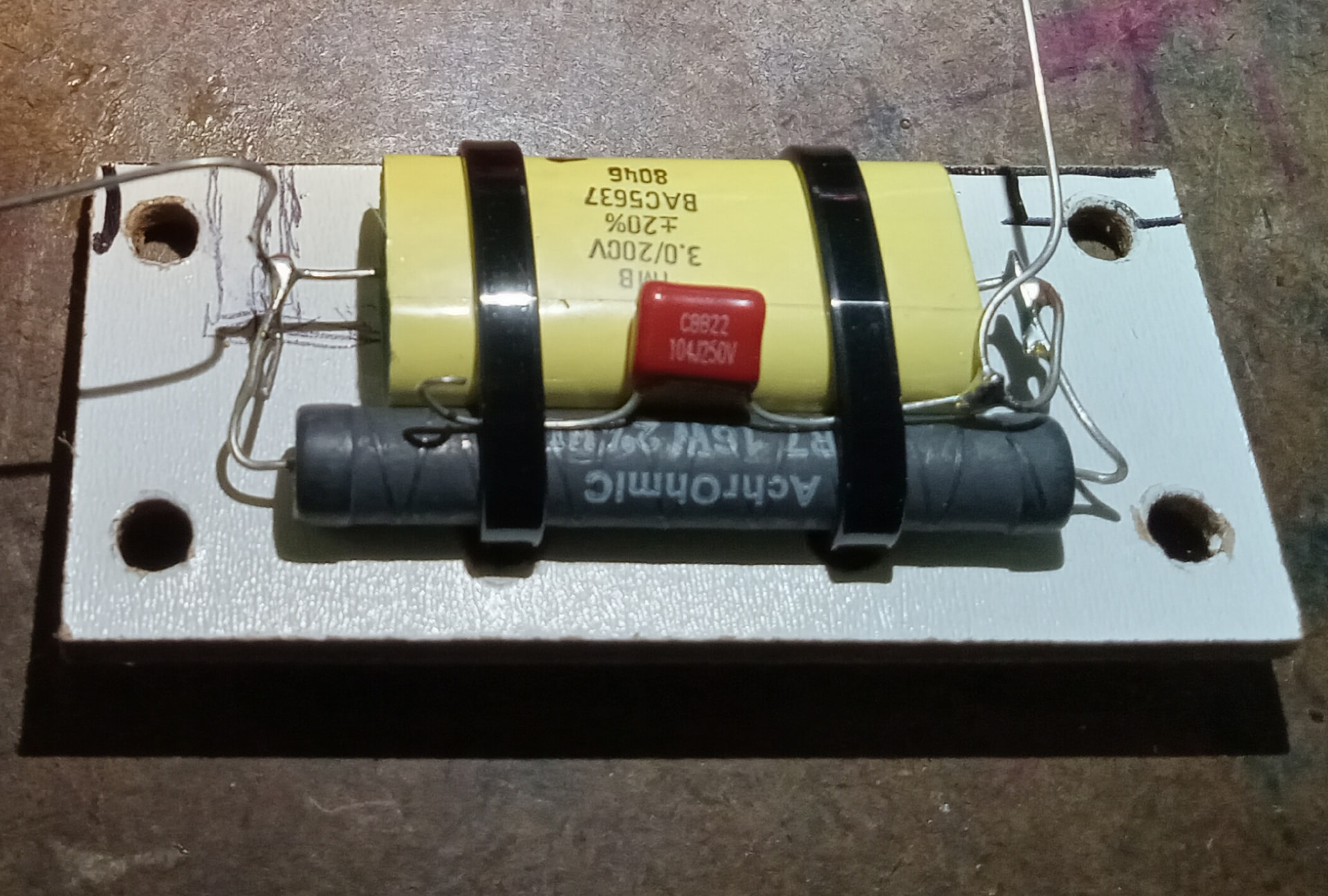
Tweeter notch board:
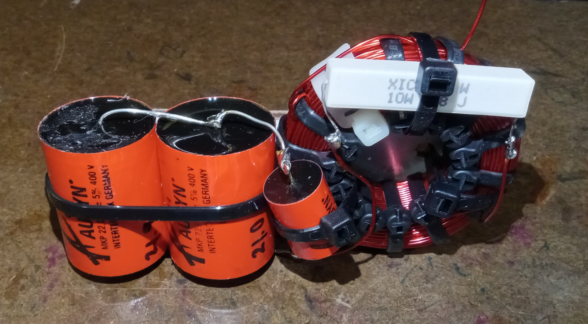
Woofer dual notch board:
Tweeter CR plus woofer tank:
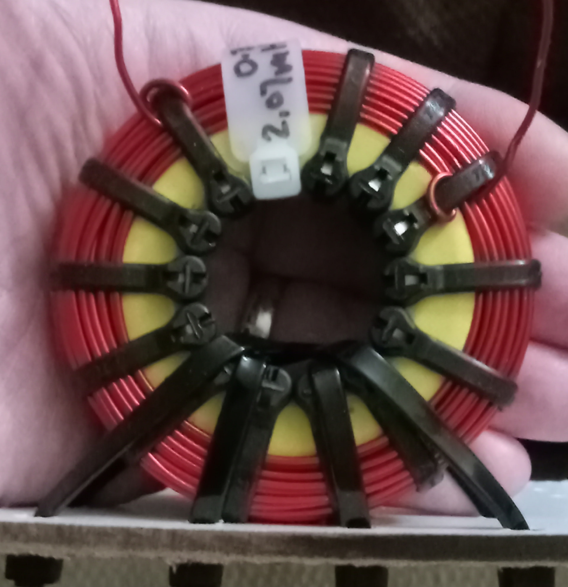
Woofer coil:
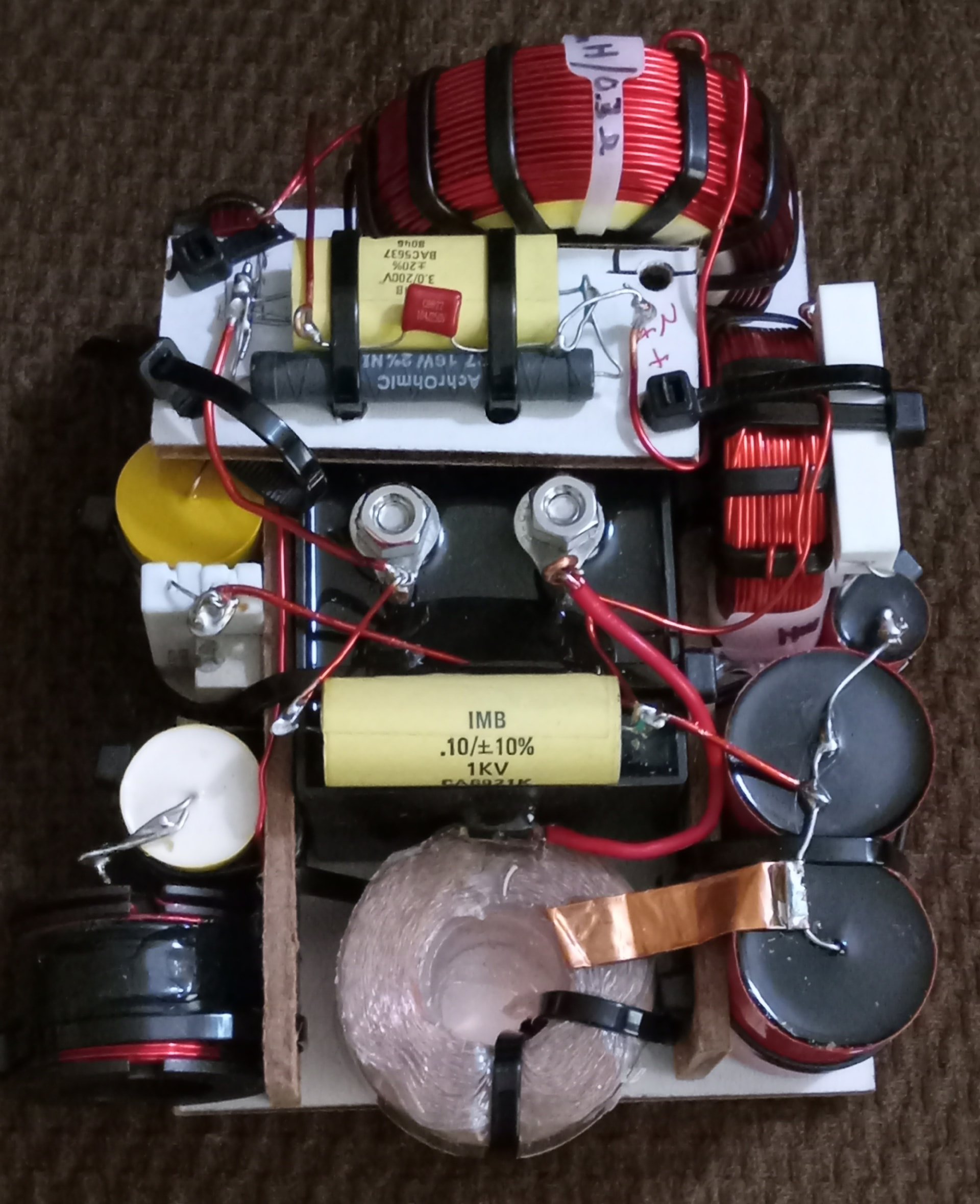
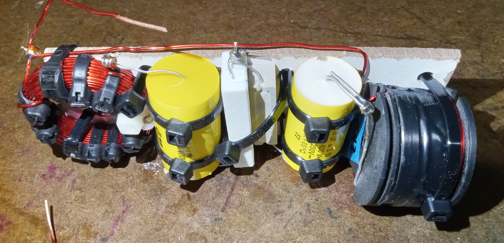
Completed w/o leads:
Tweeter notch board:
Woofer dual notch board:
Tweeter CR plus woofer tank:
Woofer coil:
Completed w/o leads:
The coils look fantastic! I am guessing the resistor tied down touching the cap won’t get hot enough to pop it.
I learned the hard way doing something like that and destroyed a cap! ![]()
That particular circuit may change slightly in the near future after I put the mic on them.
Let me elaborate a bit…
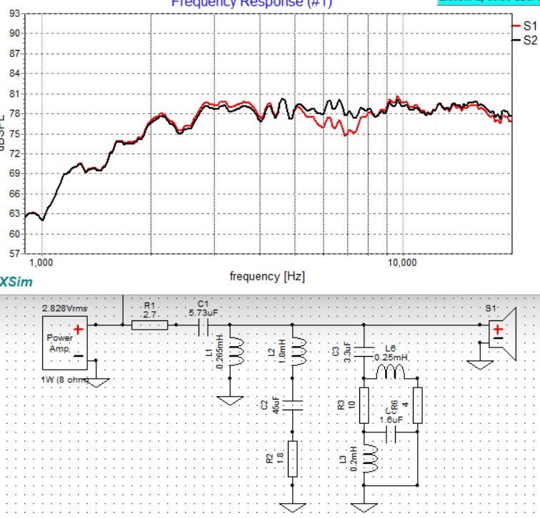
I got the leads added to the boards yesterday and fired them up. These are really good sounding drivers, but tonality needs a little adjustment. There is a hint of sibilance I want to reduce, and it sounds like maybe a peak and neighbor dip that is making them sound just a bit off. I am pretty stoked and confident I’ll sort it out easily.
Okay, I took whoops to verify, but with and without the lift 2.7uF cap in the tweeter contour was fairly dramatic. Turns out the tweeter was fairly flat without the cap in place. I tried a 1.0uF and adding a 0.5 ohm resistor in various positions, but nothing was as good as without. There is a small peak about 7kHz that sometimes I think I hear, with a 2nd order HD chaser behind it to boot, but unfortunately there is no easy way to ameliorate it. It’s too narrow band that the fixes affect more than wanted and ruin more than what is possibly needing fixed in the first place. I will just have to leave it as it is.
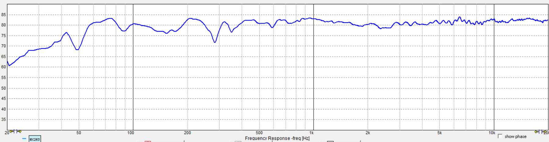
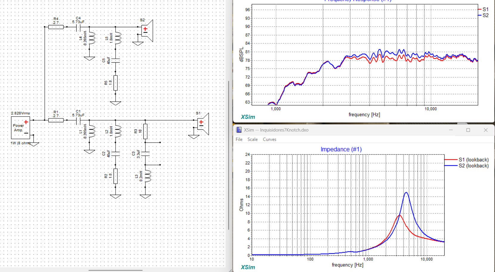
Stock as simulated:
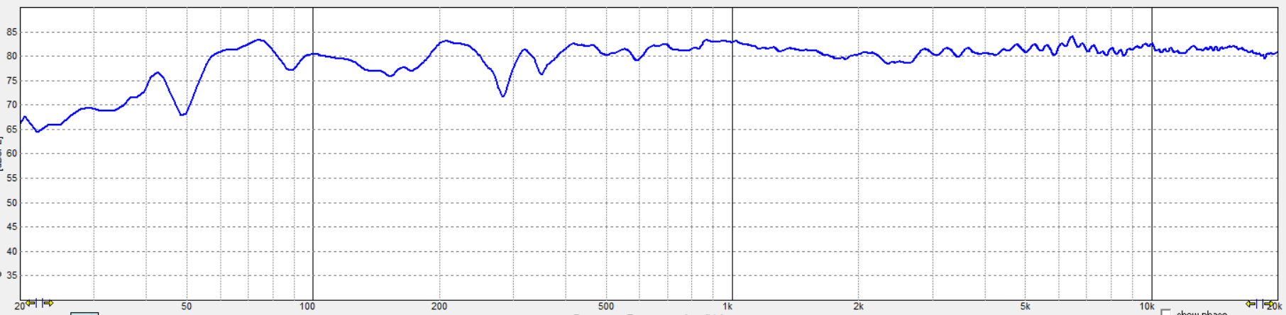
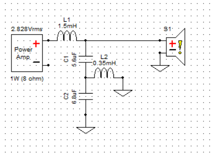
Switched to 1.0uF:
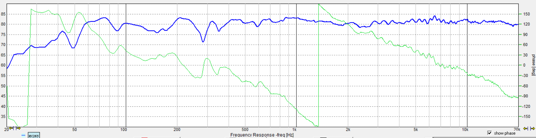
No Cap:
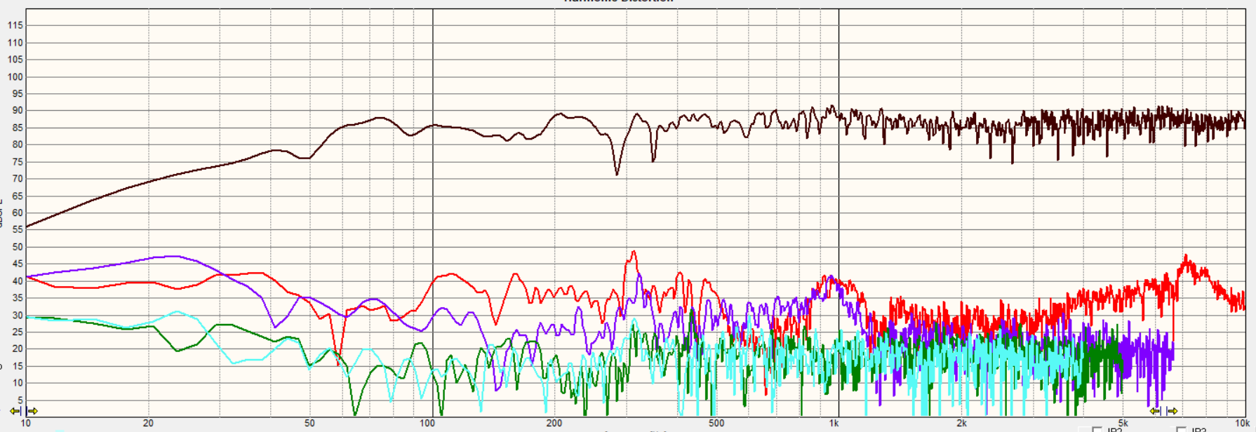
No cap HD:
I’ll have to do more listening to make sure I’m really happy with them now, but I feel I’m close to that point. The system HD is -45dB for most of the bandwidth, and what isn’t is mostly HD2.
EDIT: …and no- I could not find the 300Hz culprit. I walked around the room with my phone blaring it, then had the speaker do it, then tried 150Hz just to make sure it wasn’t a harmonic. I couldn’t find it.
less is sometimes more - looks good
When you look at the tweeter’s natural response, it is dropping pretty quickly compared to many others on the market. The sensitivity over all when flattened is likely one of the lowest I’ve used. Due to the inherent waveguide, the smaller cap can be used, but if padding is also used, you can sometimes get the top-end back a little. This is what I was thinking and initially trying to do by tilting the teeter-totter type response. Due to how this tweeter has to be used, I doubt it would have enough output for an MTM usage. It is really meant for this kind of build you see in this thread.
Had to scroll back to see the lifter (RC) at front of tweet network. Guessing the 1.8 notch for eager low end that doesnt wanna be quiet otherwise.
Eager to hear these as have only lightly experienced fiber cone or woven woof’s (small curvs, wavecor and thumpy epics).
Also curious how the tweets sound to other mag-alum tweets like in the tb w4’s and seas titan.
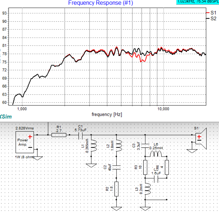
Messing around more to see if a fix is remotely possible. The shunt-series notch uses much smaller value components to get the job done with pretty good control and lower losses where I don’t want them. A plain 25 ohms across the tweeter affects the output over all, but not just the problem area. Using a set of notch values of 0.2mH/3.3uF and a resistor of variant value shows a 12-15 ohm value to be most maximally flat. 10 ohms is more recessed than flat by a hair, and 20 ohms leaves a bit of the 6-7kHz area still prominent. What could it hurt, right? I’ll have to try it out.
I mocked this up Sunday and connected them yesterday. I went with the 10 ohm, but was apparently a little overzealous. I’m on the right track to finish now, as these are much closer to where I want them, but a hair dull and lacking air. I’ll try a 12 and 15 later today to give them a little ‘life’ back. If I don’t like how either of those sound, then I may have to reduce the front 2.7 ohm padding resistor back to 2.0 ohms.
This broadband notch to flatten the tweeter hill centered at 7k is exactly what this build needed. The brash sibilance that was occasionally coming through has been mitigated. The 2nd order HD peak is not as noticeable as it was before.
I’ve now listened to several different resistances in the 10 ohm spot. Frankly, this took a lot of listening to nail down and was very finicky. Even 1 ohm added was what I call bright. I have been swapping between no added resistance, and 0.6 ohms added, and just now placed a 0.22 ohm resistor adjacent and feel its the best it can possibly be at tonal balance. Unfortunately, the 2nd order HD is still something inherent in the character these tweeters employ.
To clarify, doing the math, the initial resistor is 10 ohms even measured, the 0.2mH/20awg coil is 0.34 ohms measured, and I added in finale a 0.22 ohm resistor measuring 0.23 ohms. The total net DCR of the coil and resistors is 10.57 ohms. The difference from the simulation at lowest value of 10 ohms is only roughly a half ohm where I consider them to be dialed in.
Edit: I may even listen to these in the conference room and decide the 10.34 ohms is right over the 10.57.
Edit2: I’ll split the difference and add 0.115 ohms by paralleling 2x 0.22 ohm resistors and leave it alone.
Edit3: I added the 2x 0.22 ohm pair (in parallel) in series with the 10 ohm resistor, but placed an SPST switch across them to short them out if I want. This way, I can demonstrate what I was hearing.
At the InDIYana 2026 event, I listened and preferred the 10 ohm value on what I had presented. The extra resistors and switch will be removed.
Then, since sibilance is still an issue for me, and prevents me from wholly enjoying them, I had to dive in a little more to see what was feasible. I tried a series wired parallel notch in front of the tweeter, and could not hone in on the area in peril. I tried making a second order set of filters within the parallel notch setup by using grounded partnering components with the resistor between and felt adding 5 parts was just not worth it as my limit was set ahead of time at 3 to fix it. If I can’t do it with 3 or less, it’s not worth it.
Then I focued on the LCR across the tweeter that was used to flatten the broad hill it had before. It has to be there in the circuit for best results. I thought maybe I could add to the filter somehow to further target the issue centered between 6k and 8k for the most part. I’m also not wanting to move much outside of this area at all. Within this area, I’m looking at maybe -3 to -5dB for a ballpark. This is because that would set the HD2 level that much further down and hopefully be below the 1% threshold. That makes this a tough issue to crack.
A query;
How many of of you (me included) have seen a circuit where an electrical 3rd order highpass was used across a driver in/as the shunt of a second order lowpass circuit? It compounds the slope further on the lowpass. (I’ll raise my hand in a minute…)
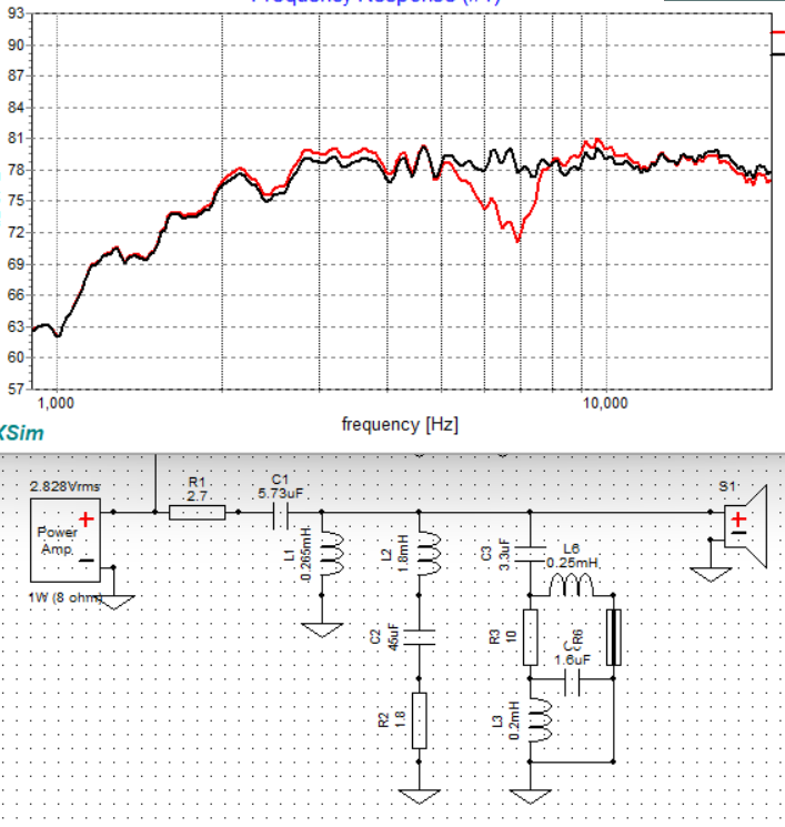
This was essentially the method I tried to accomplish in the parallel style before by trying to go with a 2nd order notch. Albeit an unfortunate name being that I am trying to accomplish and suppress a second order distortion and related sibilance, I then attempted such a quest on the shunt LCR.
It’s not a true second order notch because the secondary components are not directed to ground. What I essentially did was add a secondary notch to taper into and dip the shunting resistance lower than the nominal 10 ohm value exactly where I wanted it. It’s probably considered more of a single elliptical notch in this case.
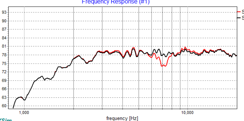
So- here is my elliptically targeted notch, and 3 different resistor values;
4 ohm:
2 ohm:
5 ohm:
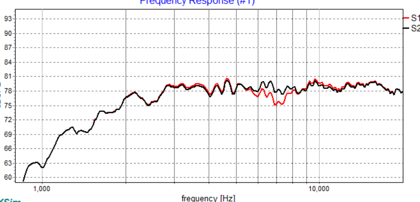
And some different arrangements;
2nd order notch:
And a couple different damped second order notches:
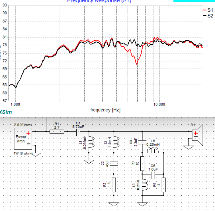
I have a feeling that one of these 2 below (reposted from above) is going to yield what I am striving for:
If the one is suppressed enough, but the range is not broad enough, all it takes is grounding the lead to broaden it a hair.
I did check impedance as well. Without going second order and adding the grounded leg, I’m seeing above 4 ohms and closer to 5 ohms net impedance for the tweeter. With the leg grounded and no resistance, the notch is set at about 4 ohms minimum. Added resistance on R6 or even R3 will only increase the minimum.
Let me also say that this is the first time ever that I have had to resort to such a circuit.
Wow, never seen that before. A notch within a notch. Learn something new every day. Thanks
Kinda funny, that’s almost exactly what Brad said.
“Is that a notch on a notch?” and then he called it Notchception.
The premise is simple, just like changing slopes and altering Q of the applied notch. Piggybacking another present circuit doesn’t cost you 6 additional parts, but only 3.
I hope it works….
Very interesting!
And now I don’t feel quite so bad about having 16 parts in my revised 8” 2-ways.
Unfortunately, Tom, that is 12 on the tweeter alone. I have 8 woofer components (9 physical parts to get the right value).