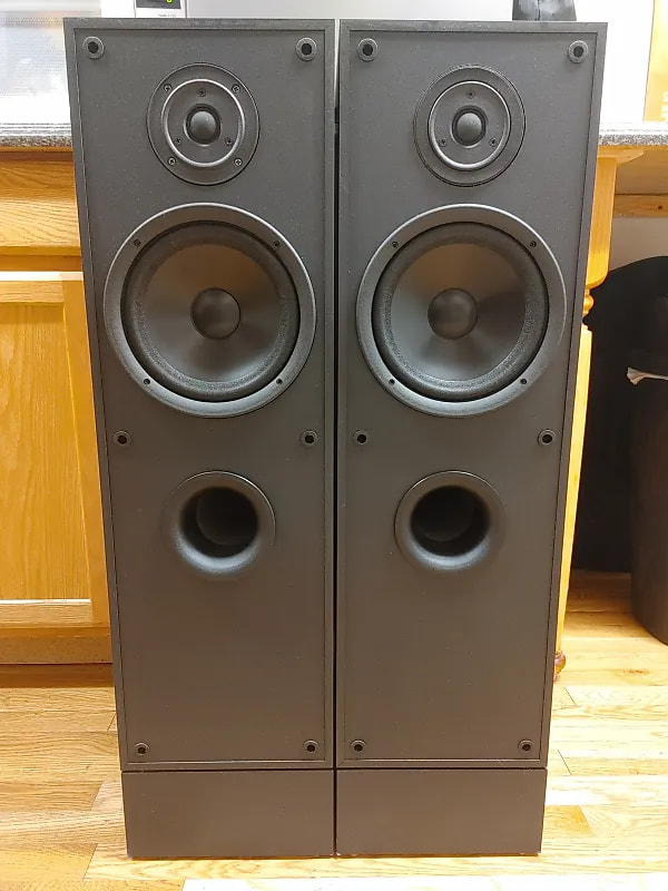
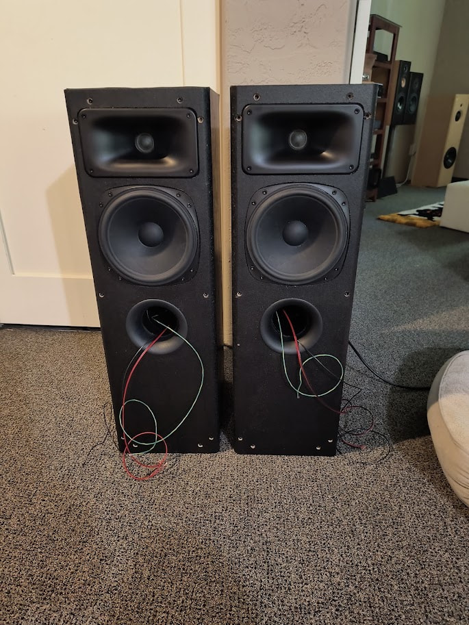
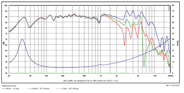
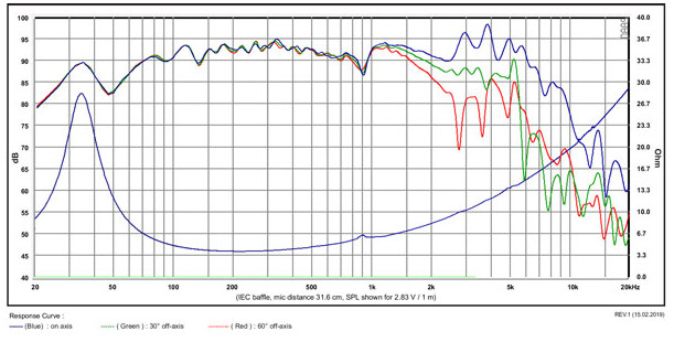
One of the projects I had in the queue for a while was an 8" two way based on the SB Acoustics SB20PFC30-8 and a tweeter in the SEOS8 dome tweeter waveguide. Thanks to JR, I had some tweeters in house that look like reasonable candidates to try with the SEOS8 (the Seas 27TFFC). One weekend, a friend let me know about a pair of speakers at a thrift store and wondered if he should pick them up and how much to offer. I couldn’t resist so I said $20 and they took it. They were old Mitsubishi’s with vinyl wrapped particle board cabinets that were at least fairly thick and heavy. The model number is M-FS8.
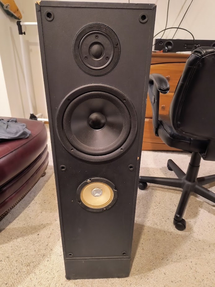
Apparently these needed a midrange, so the port was replaced with another driver. Pretty impressive, whoever did that must have redesigned the crossover.
Nope!
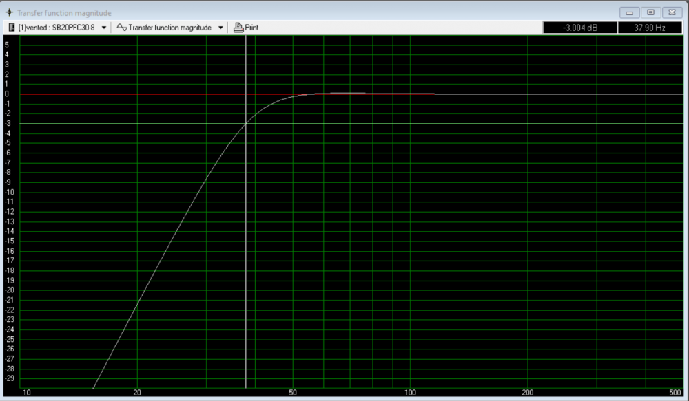
The bottom few inches is just a riser, so the overall box for modeling purposes is 32" x 10" x 12.5" out of 3/4" particle board for an overall internal volume of around 47 liters. This happens to be a favorable vented alignment for the SB’s.
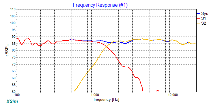
The quick crossover wasn’t perfect, but the speakers were at least entertaining (strong, dynamic bass and enough highs to generally balance that out). Consensus was that they would have made great dorm speakers “back in the day” which I agreed with. They were definitely not perfect. Below is the on-axis sim.
Post-show, I decided to finish up the measurement process and see what it would take to move more toward neutrality without losing the strengths that made the initial design fun.
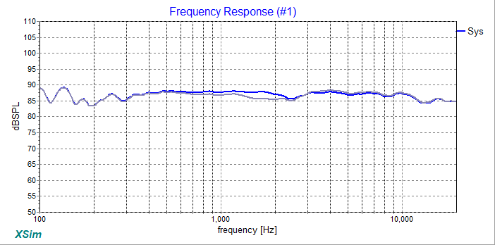
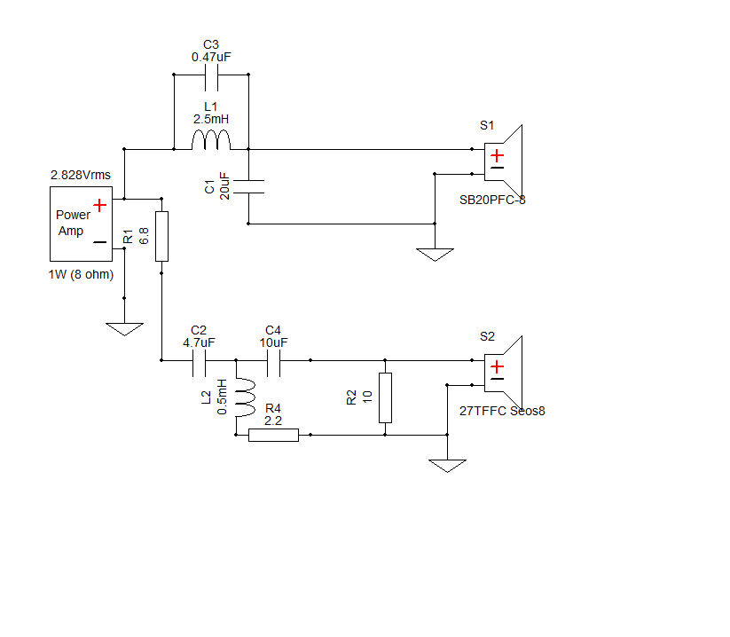
I made some changes to both the woofer and tweeter circuit. The woofer low pass got a little higher in frequency and steeper. The tweeter circuit went from second to third order electrical, but also gained a resistor on the shunt leg. The result was to fill in some of the midrange to better align the woofer and tweeter levels across the crossover region. The changes resulted in the blue curve below vs. the previous gray curve.
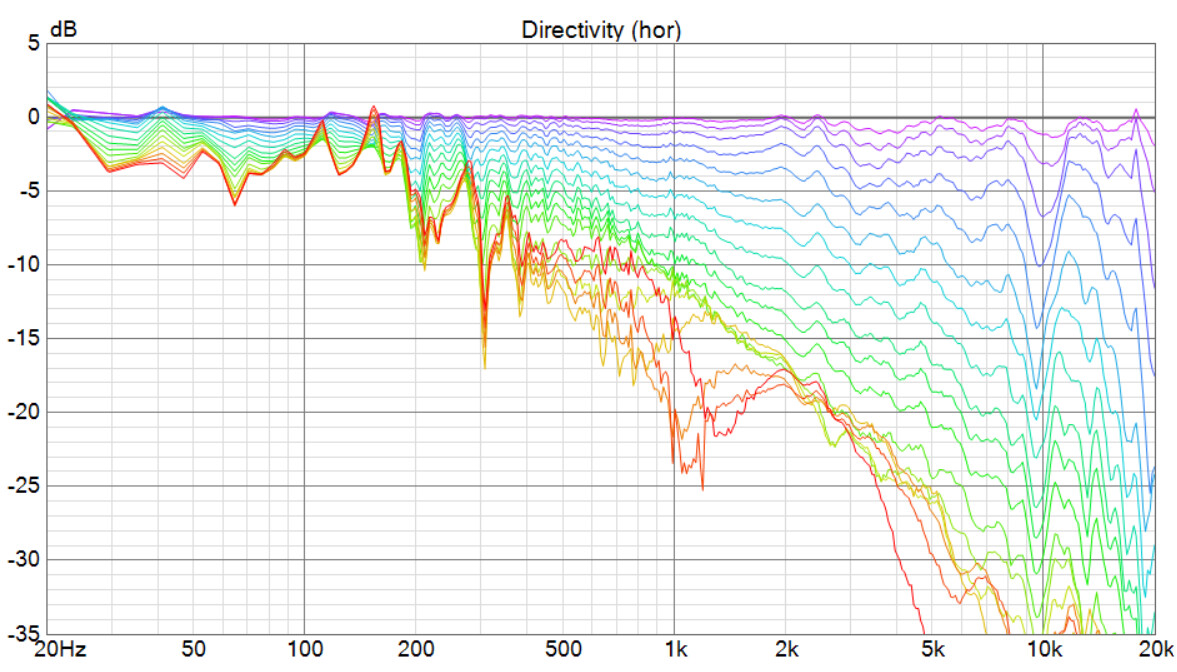
Of course, on-axis isn’t the only thing that matters. One of the reasons to use a SEOS waveguide is to align off axis response between the woofer and tweeter, so let’s take a look at that. This plot is normalized with each curve at 10 degree increments from 0 to 180 degrees. The waveguide is doing a good job controlling the tweeter off axis response.
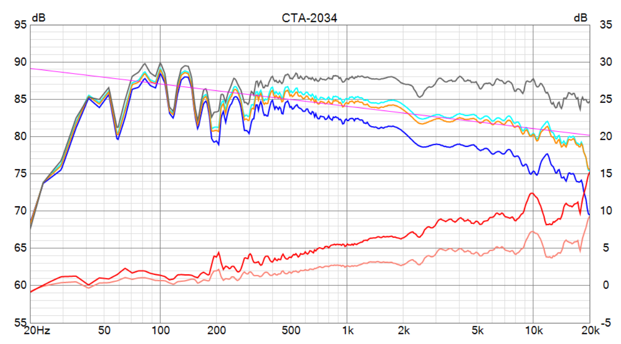
The CTA-2034 Analysis shows smooth predicted in-room response (orange curve) that aligns well with the -0.9 dB/octave slope I like to target. The red directivity curves (early reflections curve is darker red) are also smooth and well controlled.
Now, I still enjoy rocking out to these speakers, but now all of the midrange detail is also there and the highs are not fatiguing. I find myself listening to these quite a bit - even with some nice three-way floorstanders also available.
With Cinergy Audio still selling waveguides and the drivers still available, I will post the crossover design in case someone wants to try these.
Perfect, as my current 3way towers are the same width.
I I mis-spoke on the woofers - mine are the 4 Ohm version . . . They are a bit more sensitive than your 8 Ohm versions - probably need to 1/2? the value of L1 inductor but am lost on the the other 2 components you used to further shape the woofer’s response (C1 & C3).
No worries. I think there are a few changes that would be needed to use the 4 Ohm woofer. Like you suggested, one would generally use half the inductance and double the capacitance for the larger cap. The small cap creates a tank filter working with the inductor. I think keeping that at the right frequency would require adjusting it in the same direction as the inductor. The real challenge is that the tweeter level also has to change to meet the woofer. If we are lucky, we just need to adjust padding resistors, but usually such exercises also require other component changes for best results.
The dip wasn’t really intentional - just a consequence of the driver/cabinet. I will certainly agree that a dip there is far more pleasing than a peak.
 so the port was replaced with another driver. Pretty impressive, whoever did that must have redesigned the crossover.

 always seems to give me ear fatigue.