I use Gimp for sizing & rotating photos here at home. It’s a little clunky compared to Photoshop, but it’s free!
1 Like
If using phone. My android has the rotate option in the “crop” section of the pic edit menu.
The windows pic viewer i think has rotate option too.
1 Like
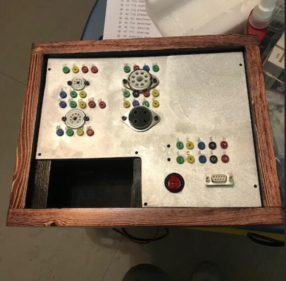
Thought I was about ready to mount the boards into the box, but wanted to move the ‘on’ and ‘hv’ red led indicators into the top panel where they could be seen. Unsoldered the leds from the board and my fat fingers shot them across the room. They are in the land of no return, until they get stuck in a toe. No mention in the constructions of the part # or specs. 
1 Like
That’s a painful way to find a part that tried to make a run for it! 
1 Like
Tomorrow, or a year from now, it is inevitable!
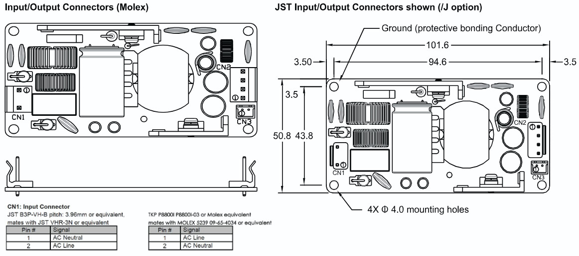

Seems odd that they are swapped depending on the connector. I would guess the circle indicates Pin 1?
Yep, the circle has a 1 inside, or maybe it’s an L, but why would they swap positions depending on connector? Doesn’t make sense.
The output also swaps around. Does this indicate it will work either direction? Don’t see that anywhere in the datasheet.
Data sheet tdk lambda css65a
The boards look like they are populated identically. So I wouldn’t be surprized if the connectors are wired the same. Unless there is some special pre-filter that requires polarization it would just be feeding to a bridge rectifier that does not care about polarization. I’m guessing it is semantics to help denote connector differences.
1 Like
Question regarding the power supply; will the output reverse if the ac input reverses? The constructions have ample warnings as to what will happen if the input polarity is reversed to the utracer board. Surely not, but not good if it does and I come across an incorrectly wired receptacle.
*Doesn’t matter which way ac input is connected, dc output polarity does not change.
On a typical linear supply that uses a transformer, rectifiers and caps, it makes no difference with regard to the polarity at the DC output. There may be safety issues related to Earth & Neutral, depending on the design of the circuit, but it won’t reverse the DC polarity.
Now if it’s a switch mode supply, I really don’t know enough about them to comment.
1 Like
@Tom_S when you tested the other 6j1p tubes, gm was given for k1/k2. k1&k2 are tied internally. Am I measuring g1-control grid and g2-screen?
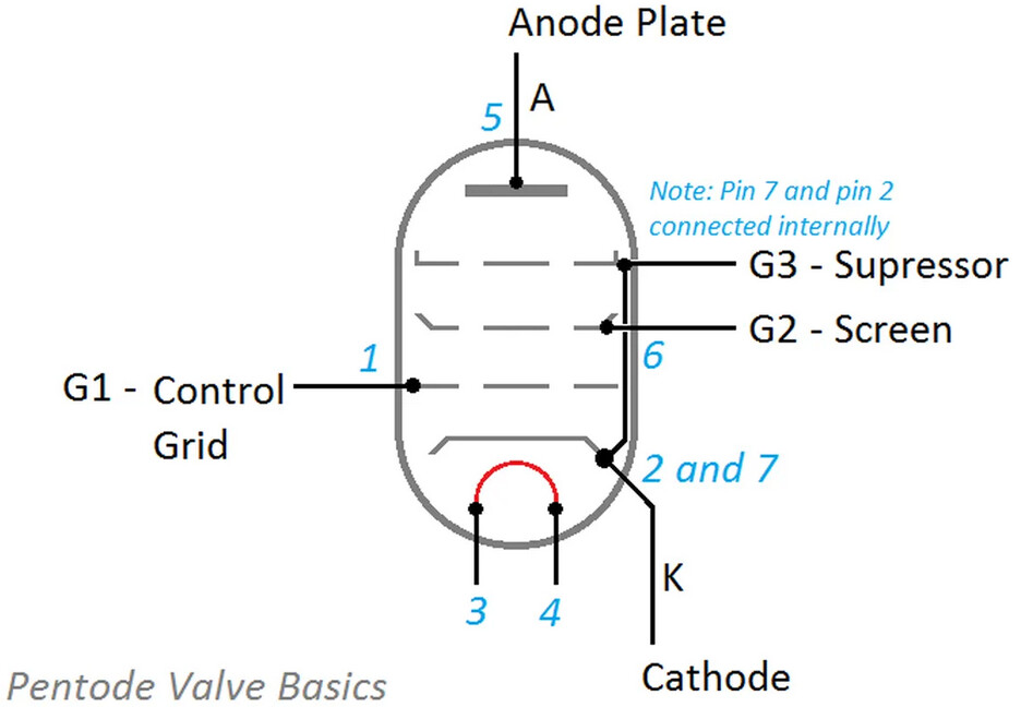
Trying to figure out what gets connected to what. utracer has k,g,s,a (plus heater). According to this it looks like S screen gets connected to g2-screen?
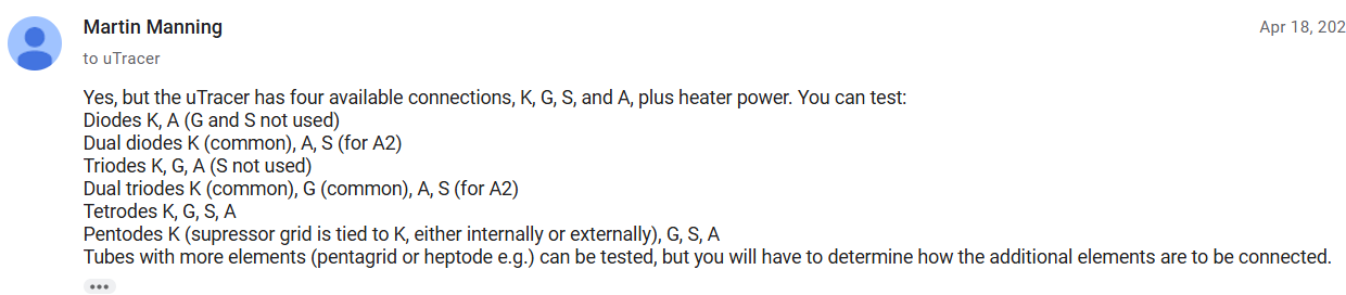
I would say yes, G1 & G2 are what you need. The Suppressor grid is tied to the cathode, but not to G2, as far as I can tell.
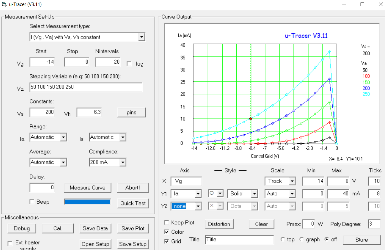
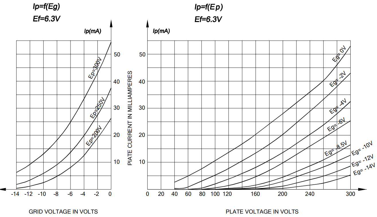
Still lots of stuff to figure out. For some reason I cannot get both sides of a 12au7 to test at the same time. Got this out of side2. Plate v for each trace on the right of graph. Don’t know why the traces don’t carry out to 0, Vg is set to 0.
12au7 datasheet,
Note to self, when the heater has a center tap and you use it, I don’t think it’s correct to use 12.6v. Heater seemed too bright, quickly set it to 6.3v.
3 Likes
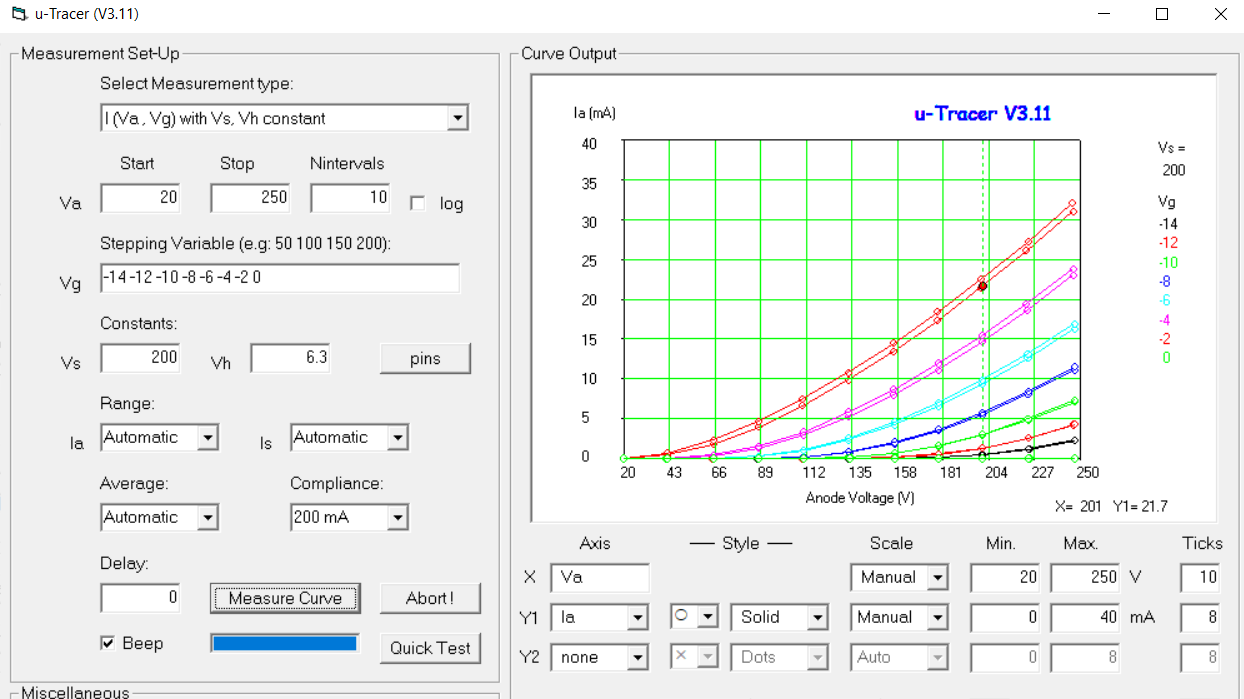
Here’s another measurement of both sides of that Russian electro-harmonix 12au7. Still have not figured out how to take both measurements at the same time. The tube was warmer on the second measurement and I assume that is why the slight difference in measurements. Pretty close to the datasheet. Still don’t know why the 0v grid line is kaput.
2 Likes
Good catch! Sorry I can’t be of any help with measuring both sections or with the zero cut off problem, but I have no idea how this software package works. I would probably try adding a +2 to the end of the Vg stepping variable list and see if that works. But that may not be possible.
Is there an auto cut-off for the current draw that might be limiting how hard you can hit the grid?
1 Like
It does have a compliance setting that limits high voltage current. Default is 200ma. Looks like that should be plenty for these tubes. The grid supply should go to zero, but not above zero, but there is a workaround for tubes that have + grid voltage.