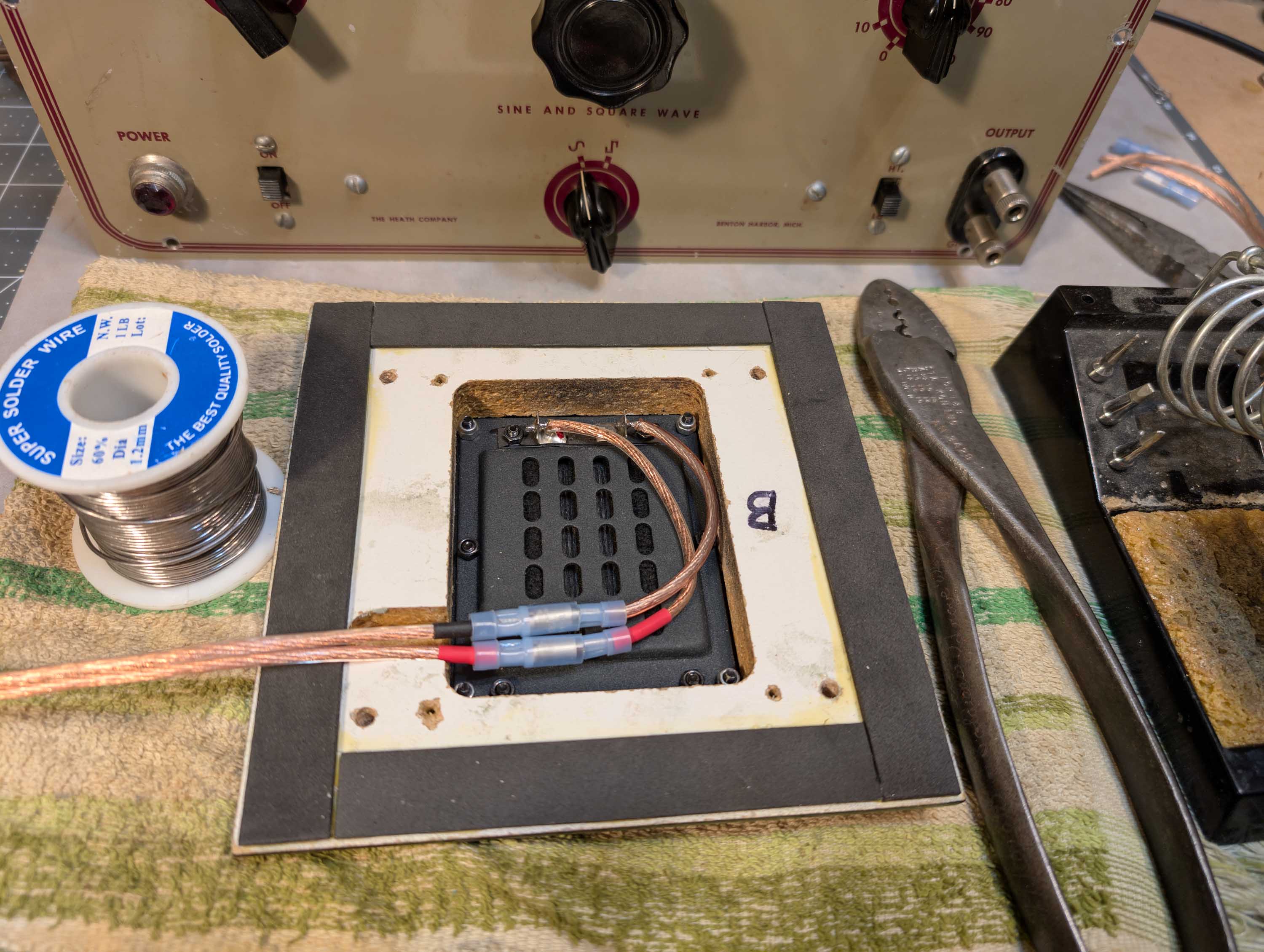
I’m getting ready to mount the tweeters onto the top of the midrange drivers using my custom adapter plates. It is a very tight fit; there is simply not enough room for the normal tweeter push-on type quick disconnects. So I soldered short 3" extension wires onto each tweeter lug. This will allow the wires to lay down flat and clear the midrange driver flange sticking up below it. I crimped Insulated bullet splice connectors onto the extensions to make it easy to remove the tweeters later on, if needed.
2 Likes
I’m trying to come up with a better name for this speaker project. Not happy with “MidSplitAbles” at this point. Was thinking maybe “PlanAxial” or maybe “RibAxial” because placing a planar/ribbon tweeter on top of a planar/ribbon midrange is sort of like creating a conventional coaxial or concentric driver. I tried AI generators, but they seemed to be of little help.
Going off vibes and maybe mixing in some satire 
Plane Janes
Thermometers
The Bleating Edges 
Edgerunners
Split Personality
Divide and Conquer
Polearms/ Poleaxes/ Halberds
Jagdpanthers (or other cool tank destroyer name. IE: Giant gun on light mobile chassis)
I like the “Split Personality”.
Another one - Bi-focals!!!
2 Likes
Rail Style
Rack and Pinion
Tweeter on a stick
Bisection
Knotty Trunks
Picture in Picture
Bump on a Log
Mast and Barnacle
How about “Split Planality” as a take off on “Split Personality”

EDIT:
- Or, “Split Planarality”
- Or, “Split Planarity”
How about “Biplanar” because the two planar drivers intersect with a small Z offset?
EDIT: Or would that be “Diplanar?”
1 Like
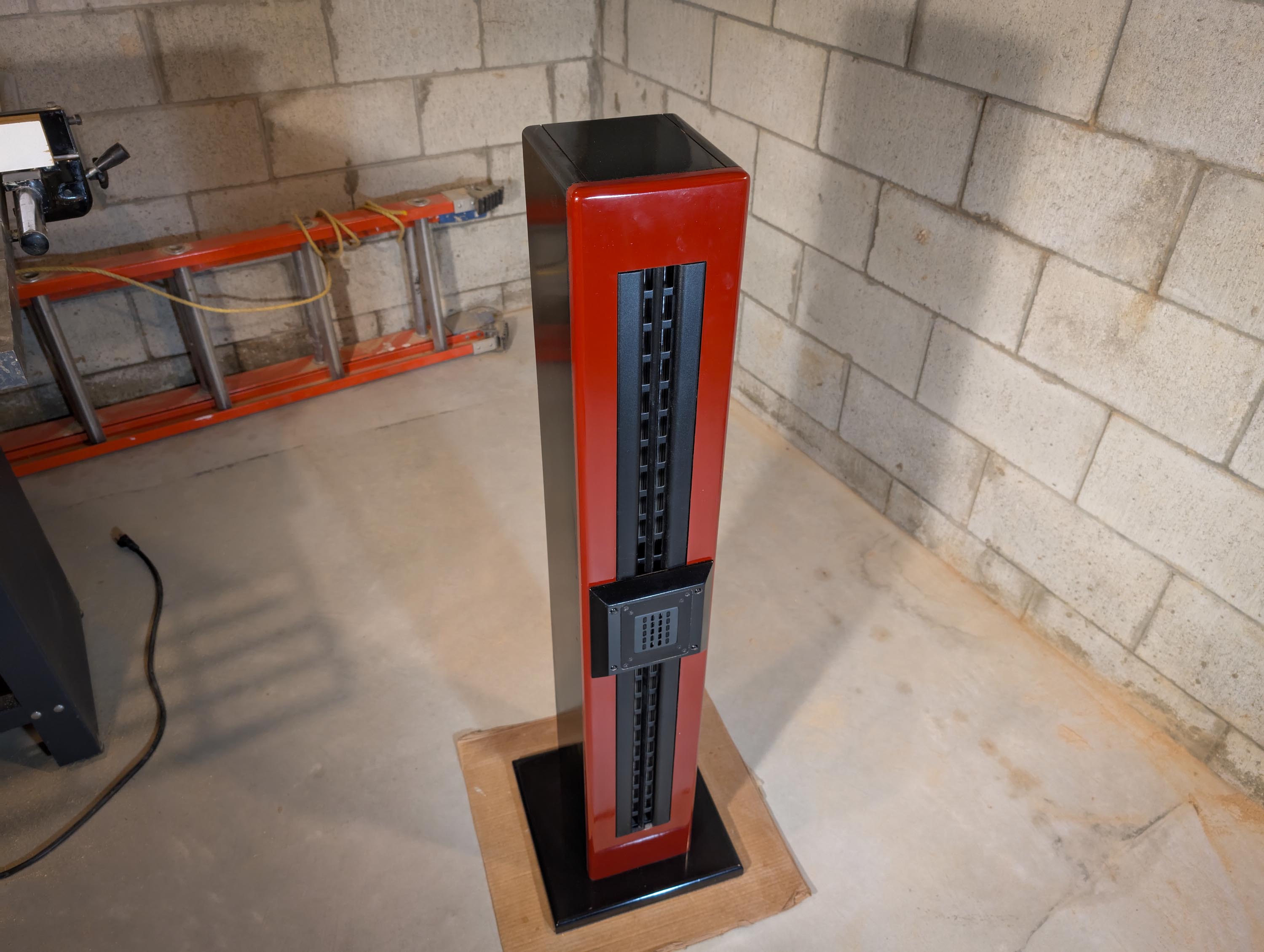
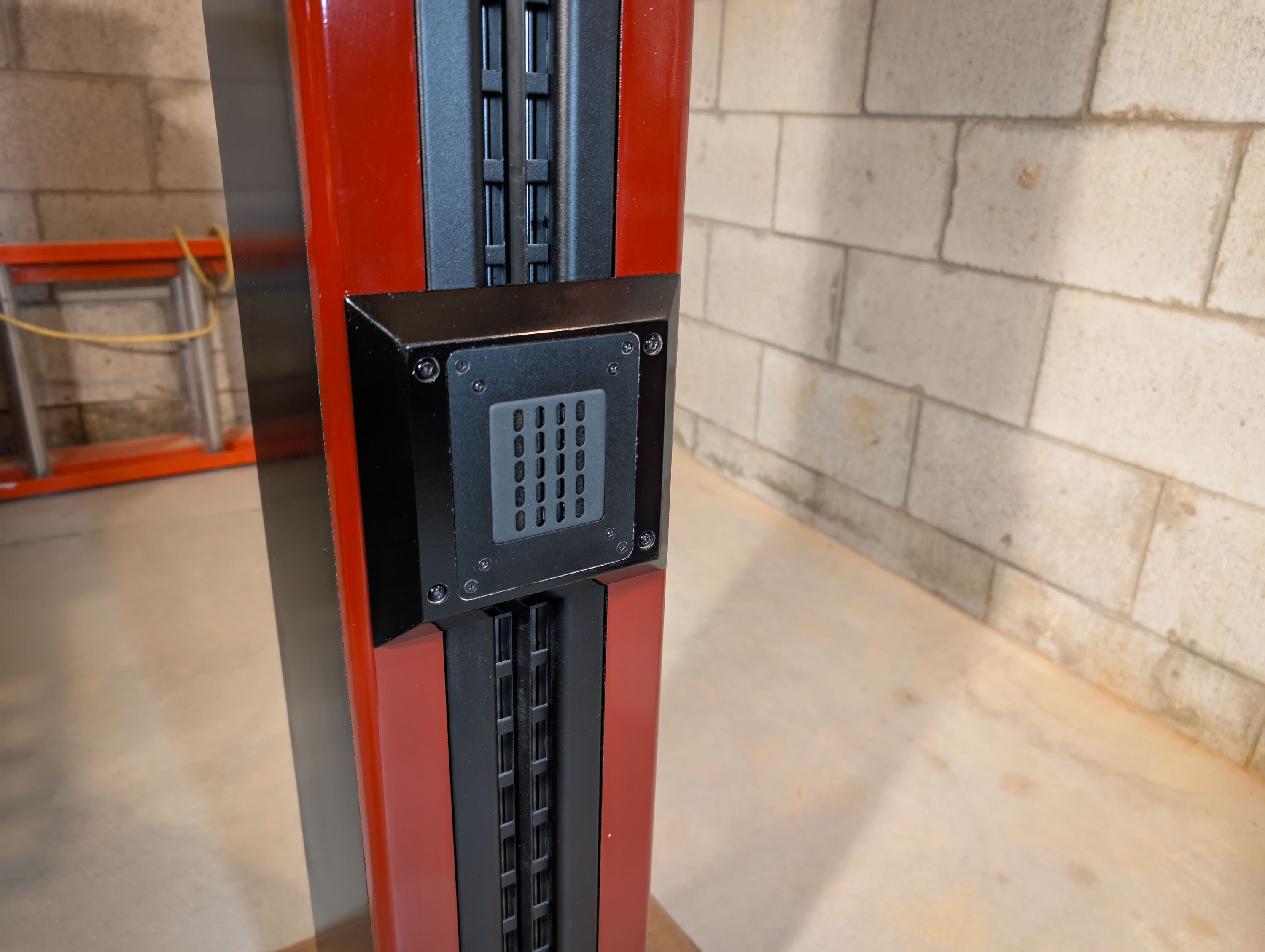
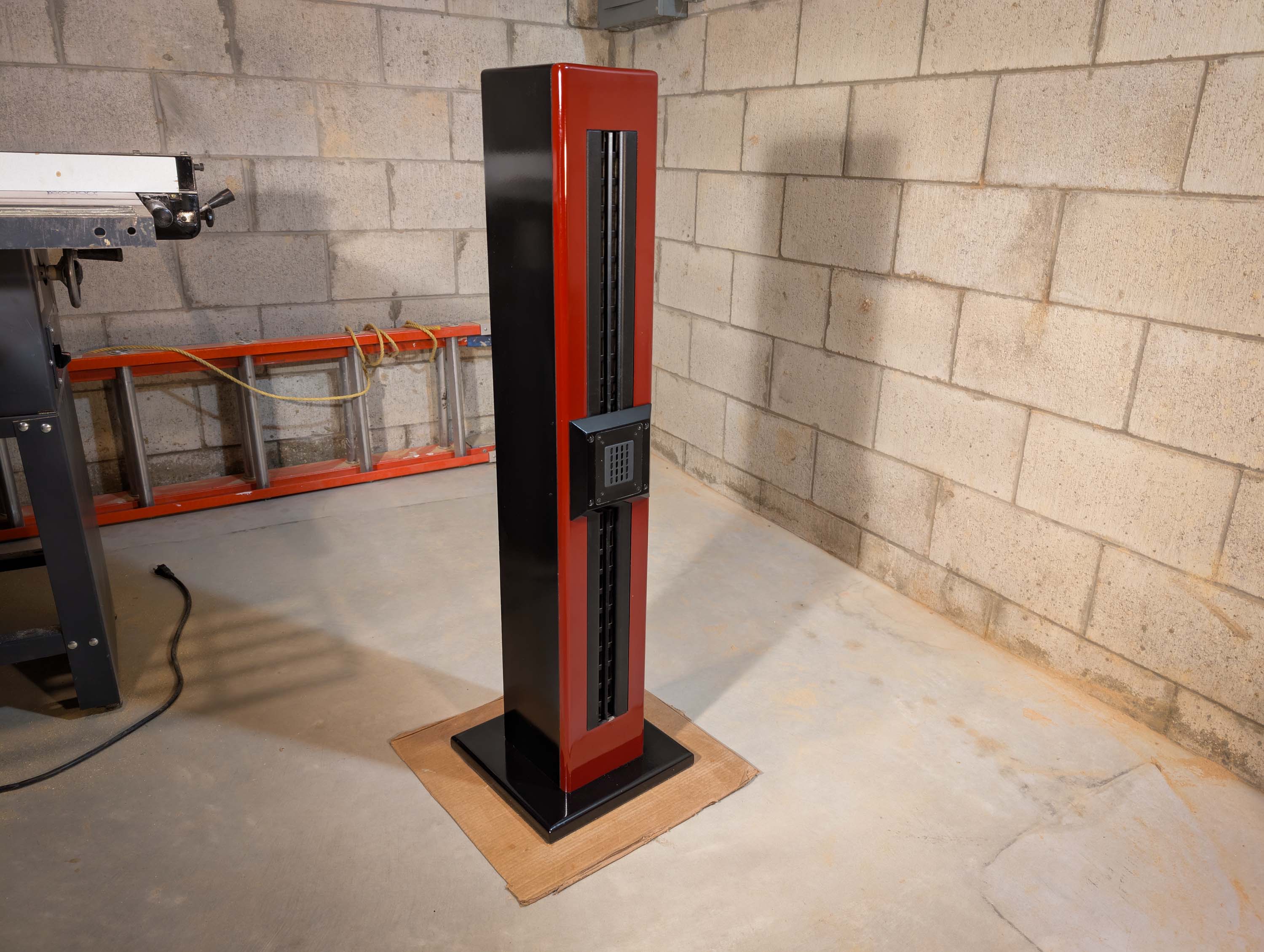
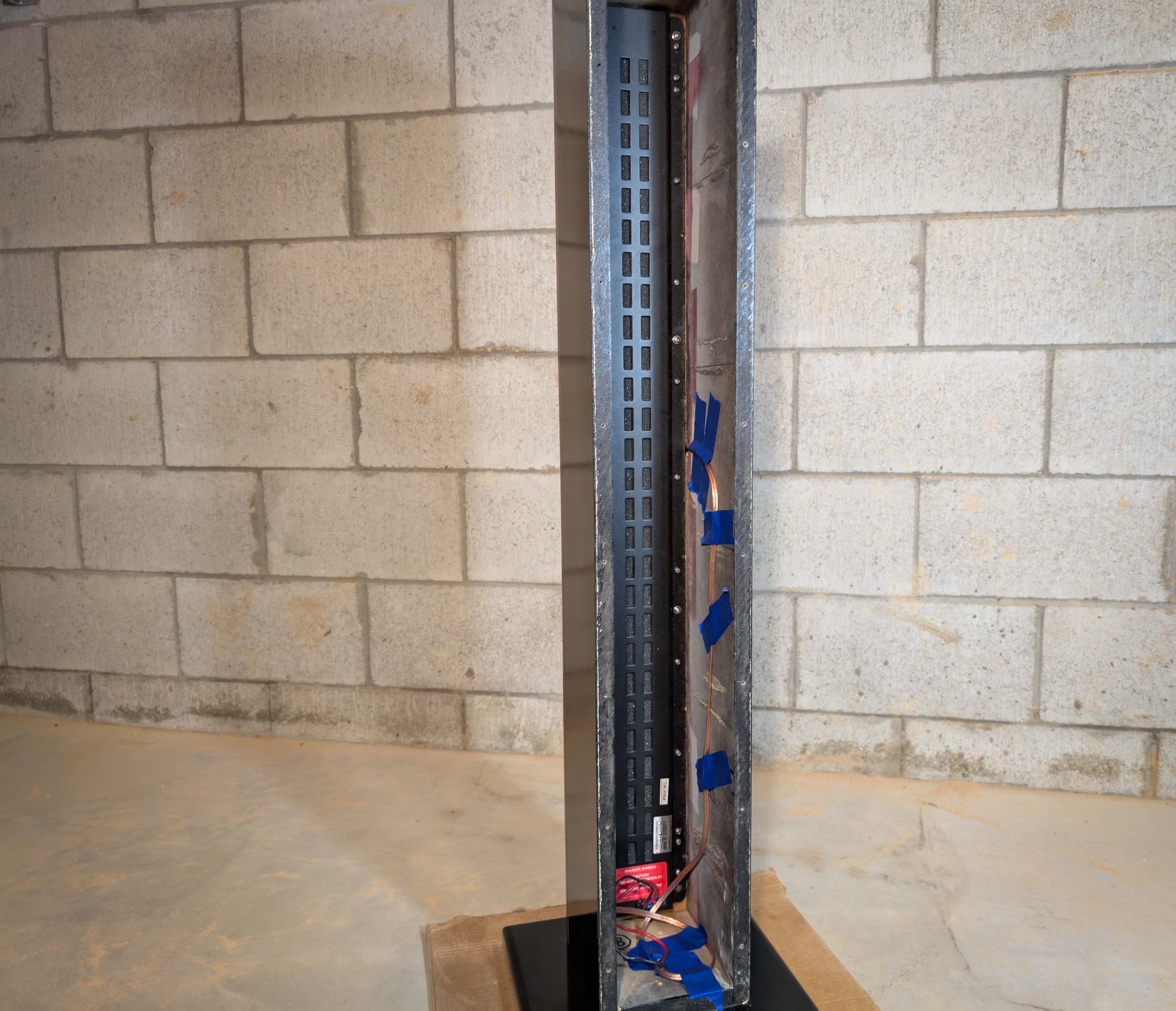
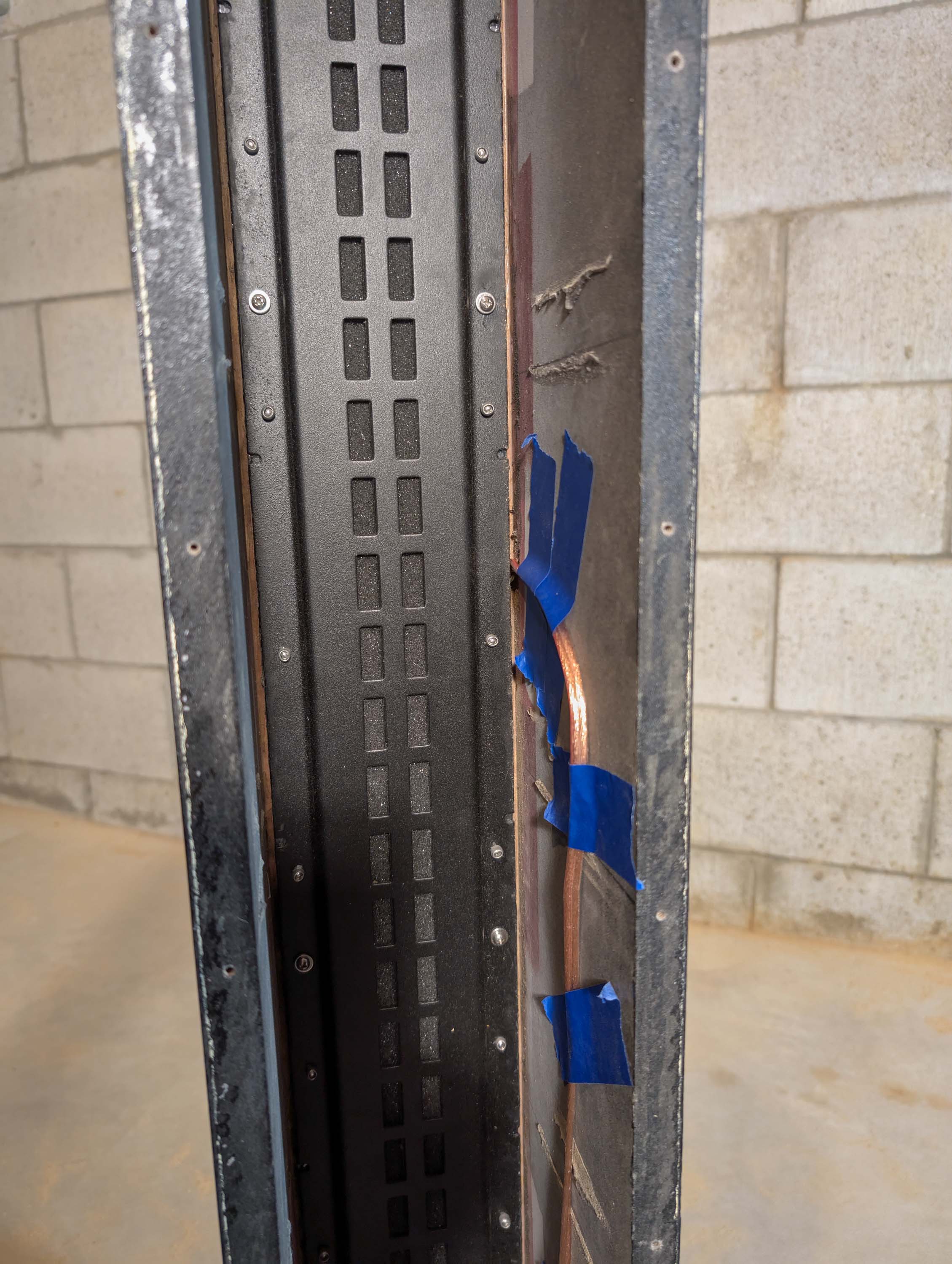
Here is what it looks like with the tweeter mounted. Wires snake around the edge and out the back of the large RD40 driver. Next up: Stuffing the aperiodic enclosure with layers of fiberglass and installing the back. Then build the woofer boxes and take some measurements.
6 Likes
How about “Neocentric?” Meaning new center. Has a nice ring to it and seems to roll off the tongue much better than “MidSplitAbles.”
2 Likes
As I think about this some more, Neocentric would probably be OK but at the same time, it seems a little bit boring. Maybe something like “NeoSplitty in the Middy” would strike a better cord.
1 Like
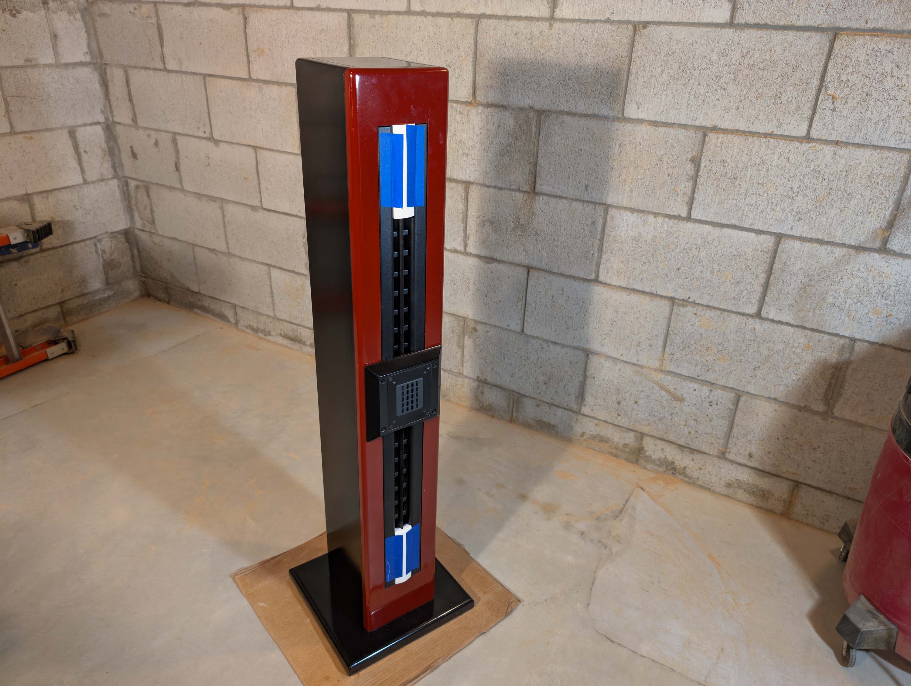
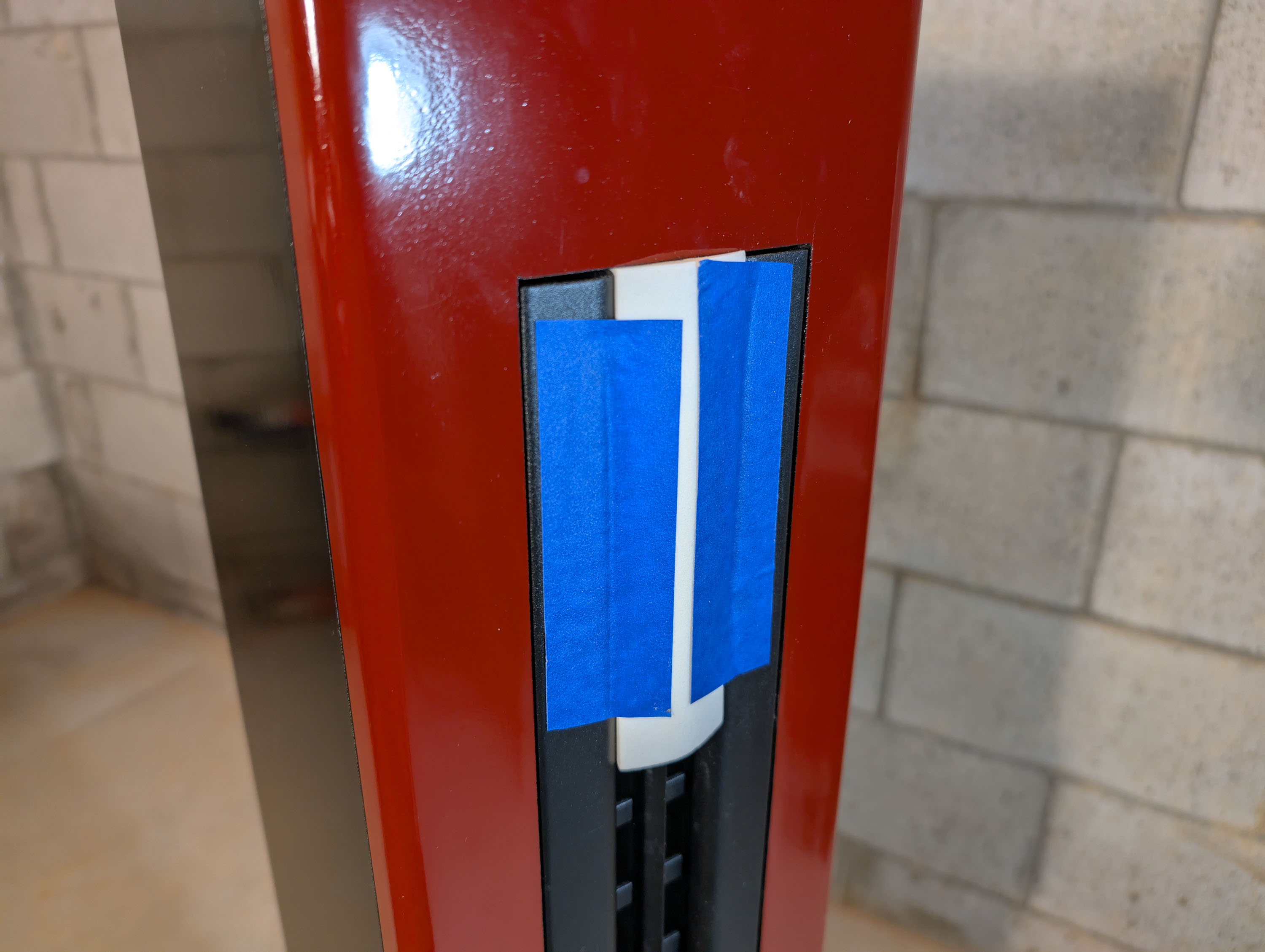
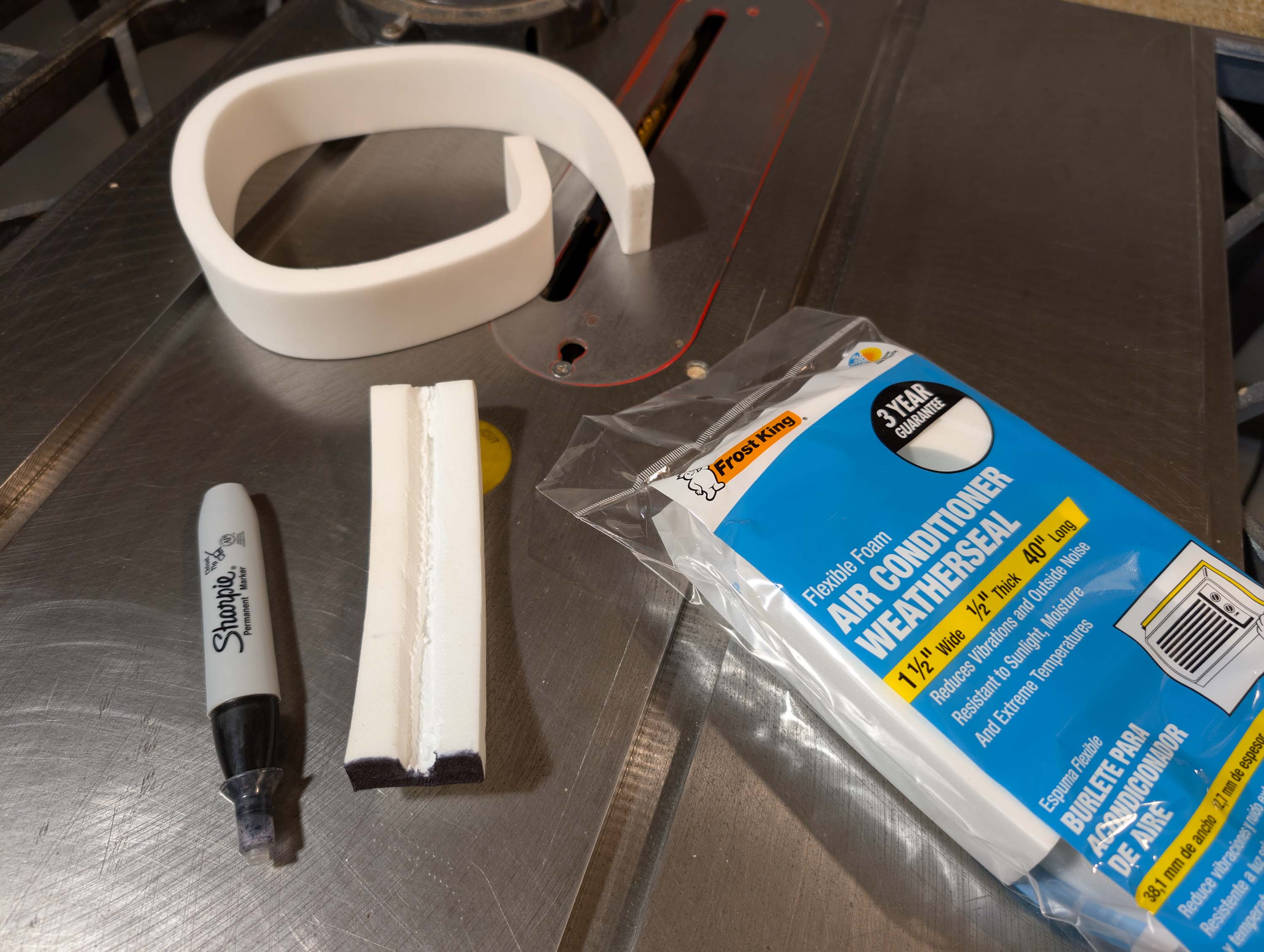
The 35.5" vertical dimension of the ribbon will cause the vertical lobe to narrow into a real “head in the vise” type situation. So my plan is to widen the vertical lobe by blocking off about 5 to 7 inches or so at the top and bottom of the ribbon. Frost King makes a closed cell flexible foam air conditioner weatherseal that seems like it will work well in this situation. It measures 1.5" wide by 0.5" thick and if I cut a “V” shaped slot down the center, it will press fit snugly into the ribbon cavity and seal it off.
In the picture below, the foam is easily held in place with masking tape. This makes it possible for me to take measurements and experiment with various lengths to widen or narrow the vertical lobe until I get it where I want it. When I get done experimenting, I can replace the masking tape with a large piece of self-adhesive black felt. This should look much better.
The only problem is that this weatherseal product only comes in white. Which will look horrible if not covered up. So I will need to “paint” the end of each foam section black with a sharpie so that it blends in with the black driver flange along the edges. Self-adhesive black felt with cover the top part of the foam.
2 Likes
When I take measurements, I will be looking for internal cavity resonances caused by the foam. The ribbon element is exactly 1 inch below the flange surface. When I press the foam into the cavity, it is held about 1/2" above the ribbon element by the waveguides cross bracing. So, I’ll be looking for a resonant dip or peak of about 13.5kHz relating to 1/2 wavelength at the 1/2" distance.
The length of foam blocking pad is about 5 inches, so I’ll be looking for another peak or dip somewhere around 1.3kHz.
1 Like
I’m not meaning to poo poo on your project at all, but it seems like a huge shame to have such gloriously long planars only to neuter them with foam blockers. Is “head in a vice” really such a bad thing? I never get down, get back up again, then shake my booty when enjoying good sounding tunes. Are you buiding these for a large crowd listening area?
1 Like
Yes, I’m designing for a listening window, not a specific listening position. In addition, I have several years of listening experience under my belt with these long ribbons. They have a very detailed sound quality when running full range with a sub crossed at 200Hz. But they also have a very strange type “phasy” or “etched” type sound quality to them that I find very irritating. I am fairly certain that this has something to do with the comb filtering problem in the vertical domain when trying to use them full range. Dropping the xover to 2500Hz and using foam blockers should be able to improve the sound quality considerably; not make it worse. But time will tell.
The nice thing about using foam blockers is that it will be very easy to adjust their length by trial and error, listening to the effect of changing the vertical lobe and power response. I should be able to compare the sound of various lengths as well as listening to no foam blockers at all. There will also be foam blockers in the middle, underneath the tweeters, but they will be a permanent part of the tweeter’s sealed enclosures and cannot be removed.
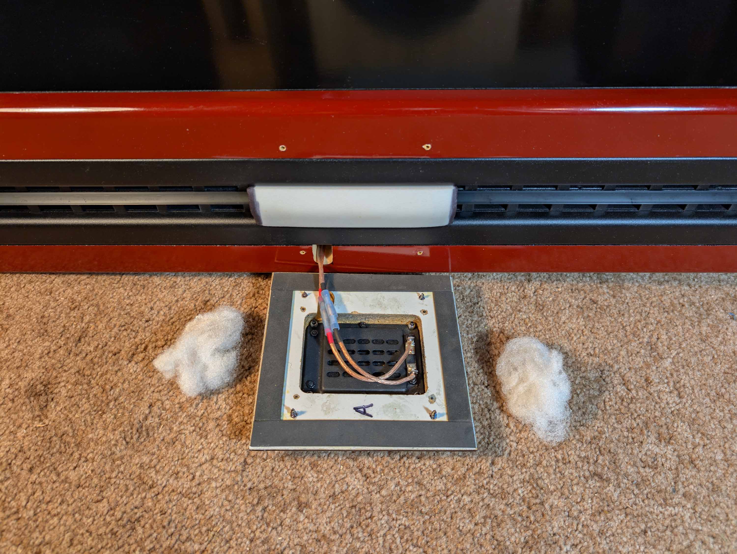
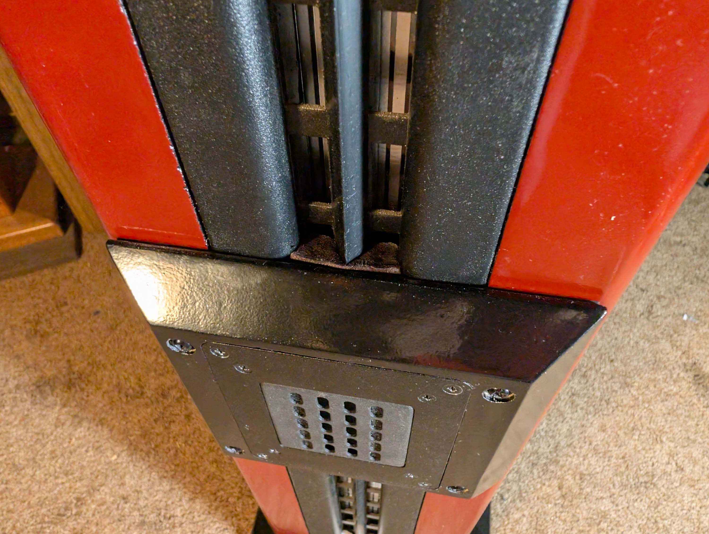
Here are some pics showing the tweeter enclosure. A 1.5" x 0.5" x 5.75" closed cell foam blocker is inserted into the ribbon driver cavity. The foam does not touch the ribbon, it is press fit into a position about 0.5" above the ribbon.
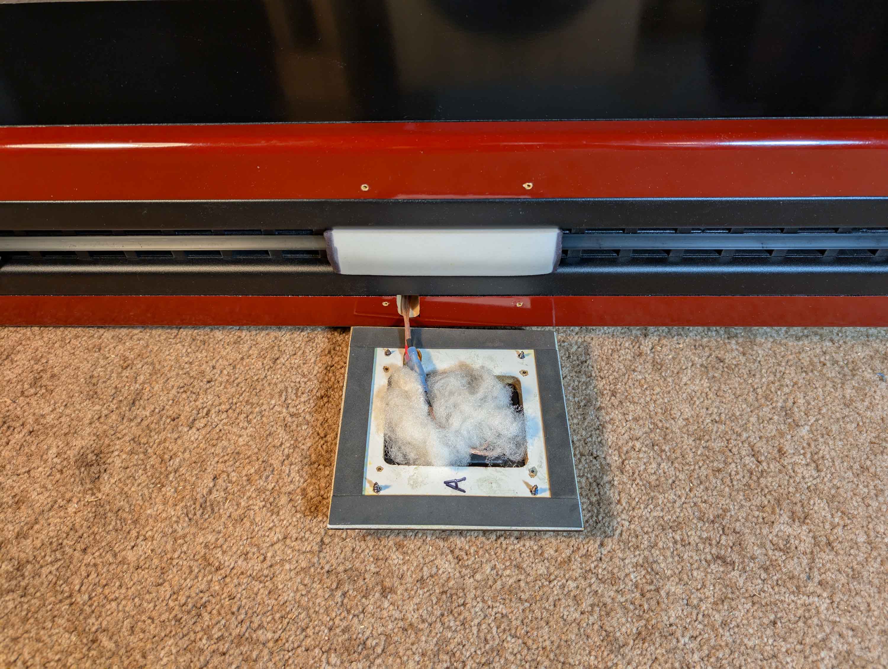
Then I install a very small amount of Acousta-stuf in the tweeter enclosure:
Then I install the tweeter + adapter flange into position onto the main enclosure using 4 screws. This creates a small, completely sealed enclosure behind the tweeter. The RD40 ribbon output is completely blocked by the foam:
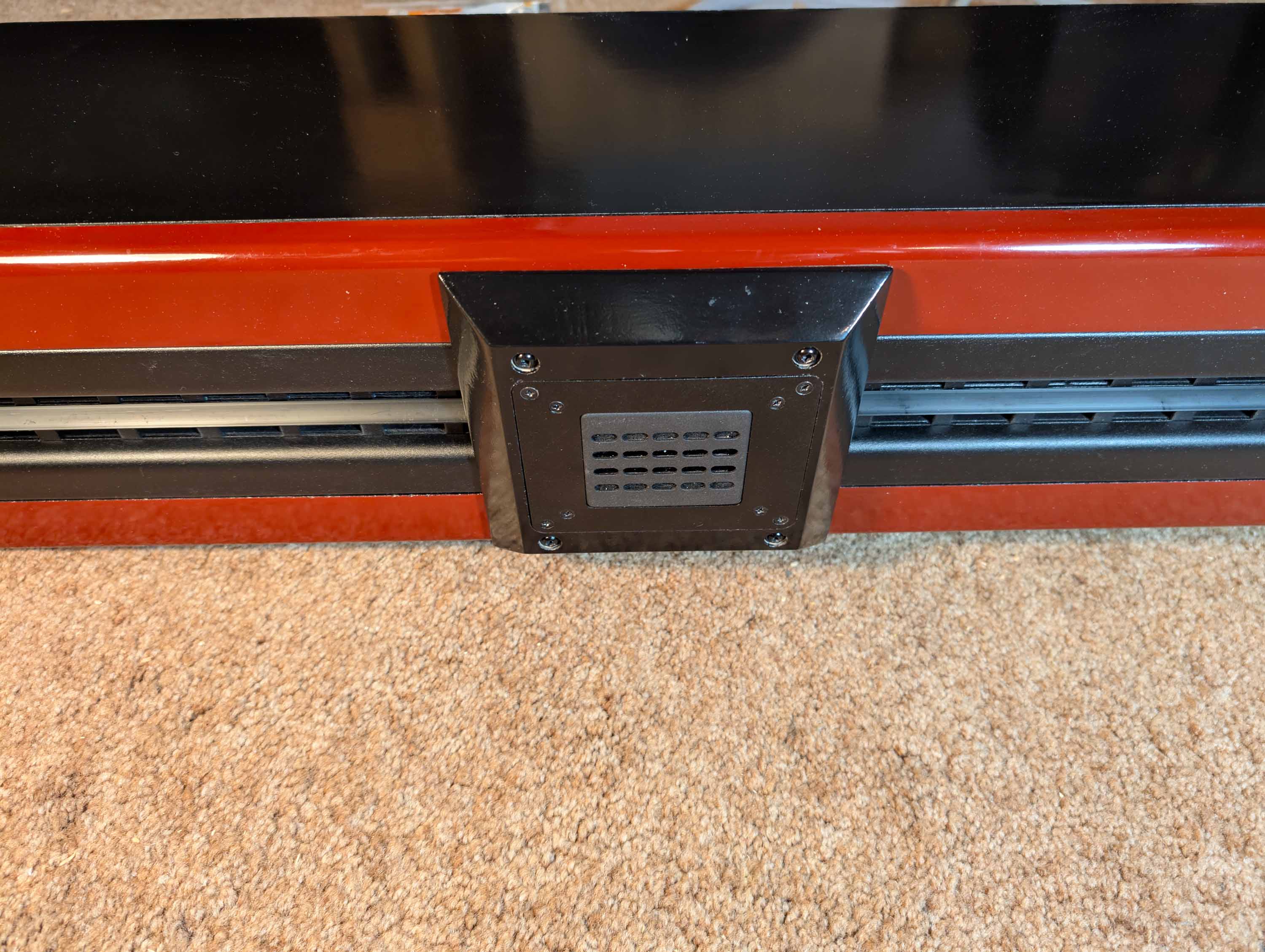
Here is a view showing the top edge of the foam blocker. I “painted” the foam black with a sharpie to make it look better.
1 Like
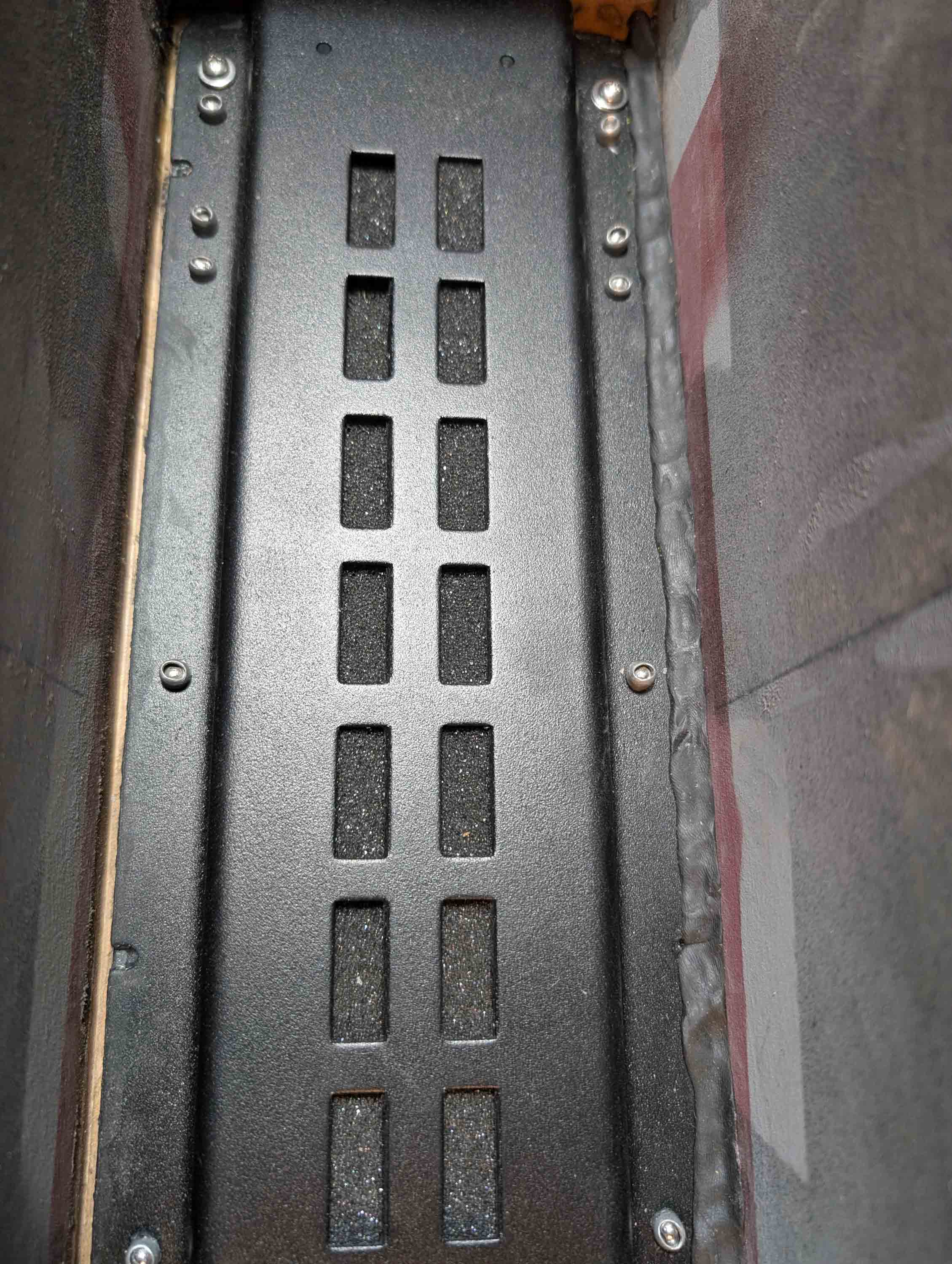
Ani, here is a photo of the RD40’s being sealed in from the backside with flexible rope caulk. The right side is done, the left side is still open. This is not the Mortite brand stuff, but the stuff that Parts Express, back in the day, always gave away free to customers with every driver purchase. I had piles of this black rope caulk on hand, left over from previous orders. So I used it all up on this project.
Thanks Bill, must be way back in the day, as I don’t have any! Is it reusable and does it come off easily or it’s it like silicone caulk?
Ani, I am finally to the point of taking some measurements. Just the raw RD40 driver without crossover of any type. No tweeter or foam blockers were in front of the drivers for these tests. All measurements were with OmniMic, 1 meter on axis, 5ms gate, blended mode.
I loaded the curves into VituixCAD and did an SPL comparison of 4 different aperiodic style loading configurations. I also ran impedance curves on each configuration, but will not be posting them because they are all pretty much flat lines at 6 ohms. But I’ll post the data if someone wants to see it. Ignore the 5 to 6kHz response glitch. The RD40 ribbon element rings at these frequencies. The manufacturer recommends a notch filter to tame this problem, which I used successfully on my old Plan-Tanic speaker design. But this time around I will be crossing somewhere in the 2.5 to 3kHz range, so the necessary LR2 filter plus a tank should effectively squash this problem area.
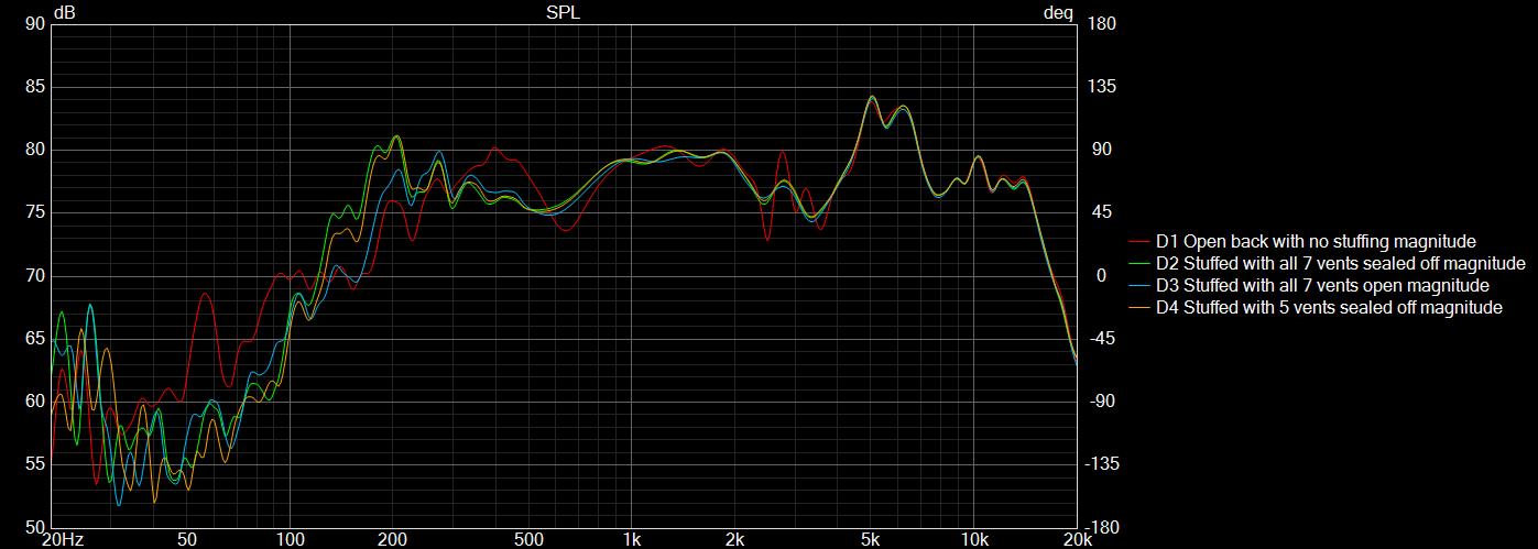
The red curve is open back completely unstuffed (see pic below). The glitch from 2.5 to 3.5kHz is an internal cavity resonance of the empty 41 x 6.5 x 5" box. The big dip at 750Hz is related to the front to back cancellation distance. It tends to go away somewhat when I started stuffing the box or sealing off the vent holes.
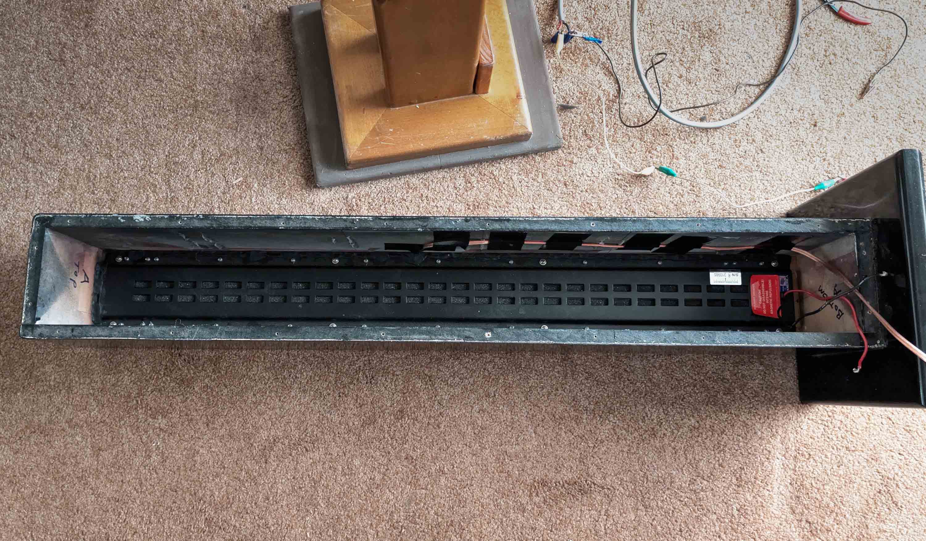
The blue curve is with the box completely stuffed with Acousta-stuf, then 1.5" of convoluted foam on top of that, and then the back installed with all 7 aperiodic vents completely open. See pics below:
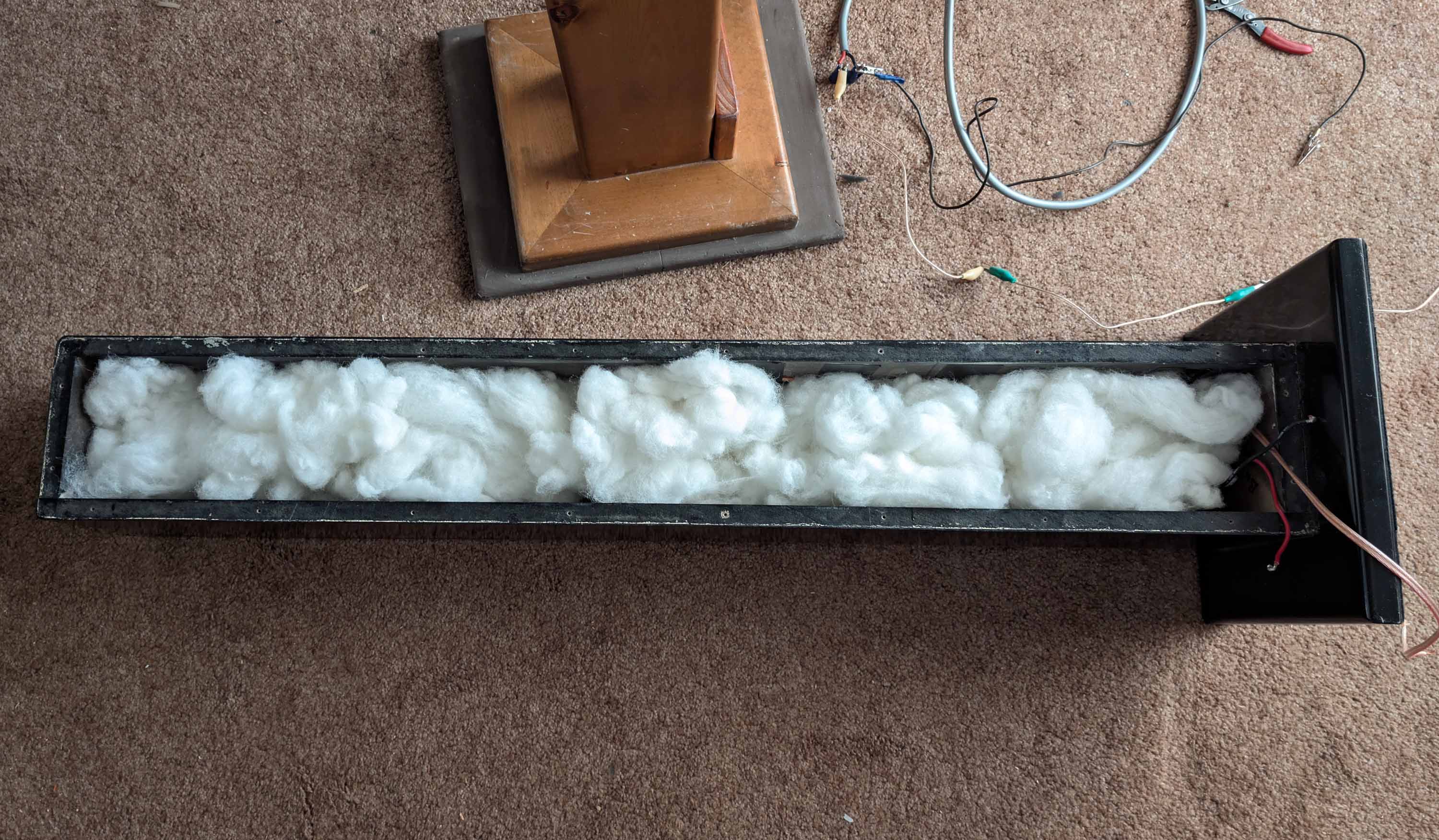
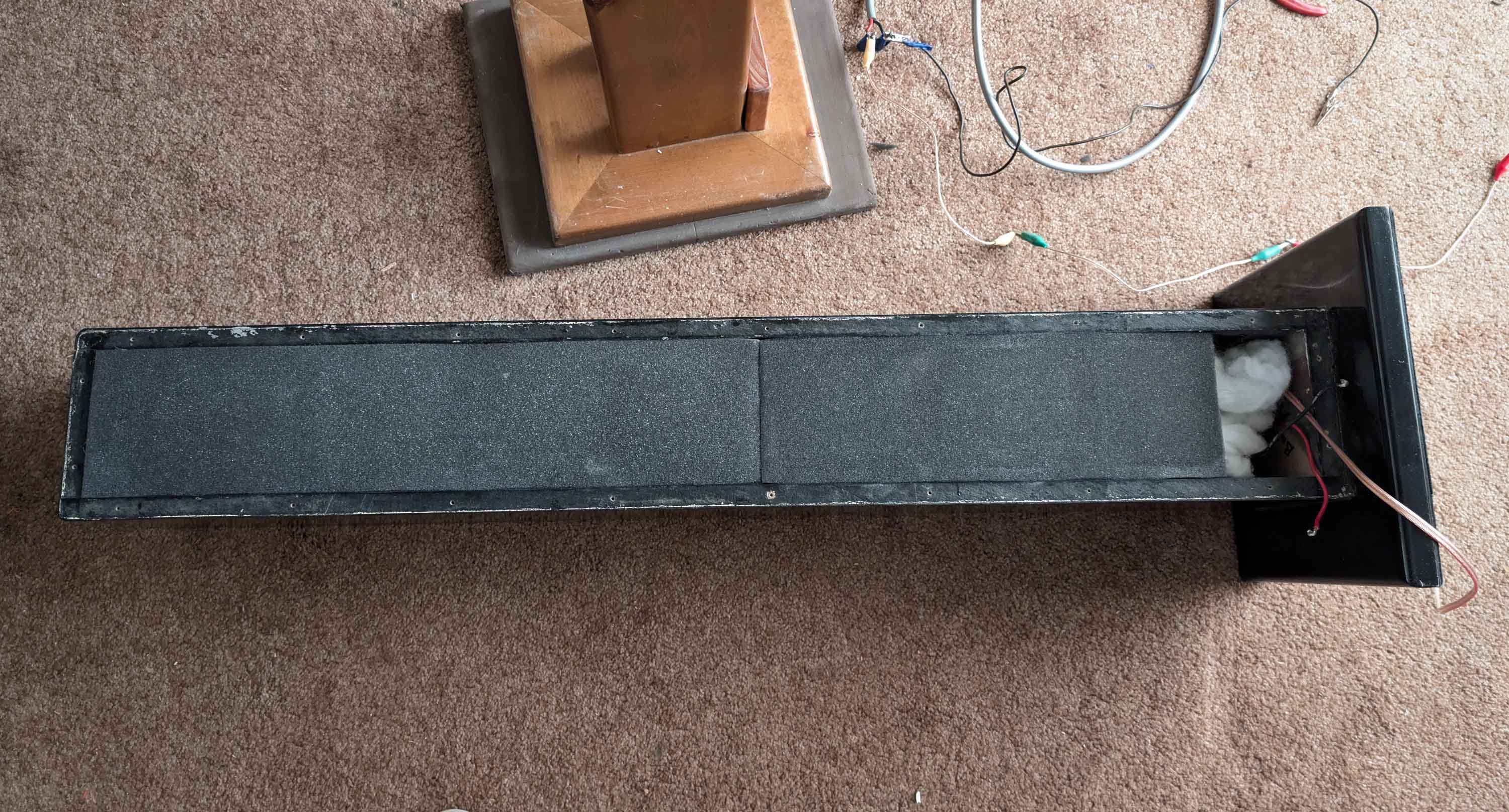
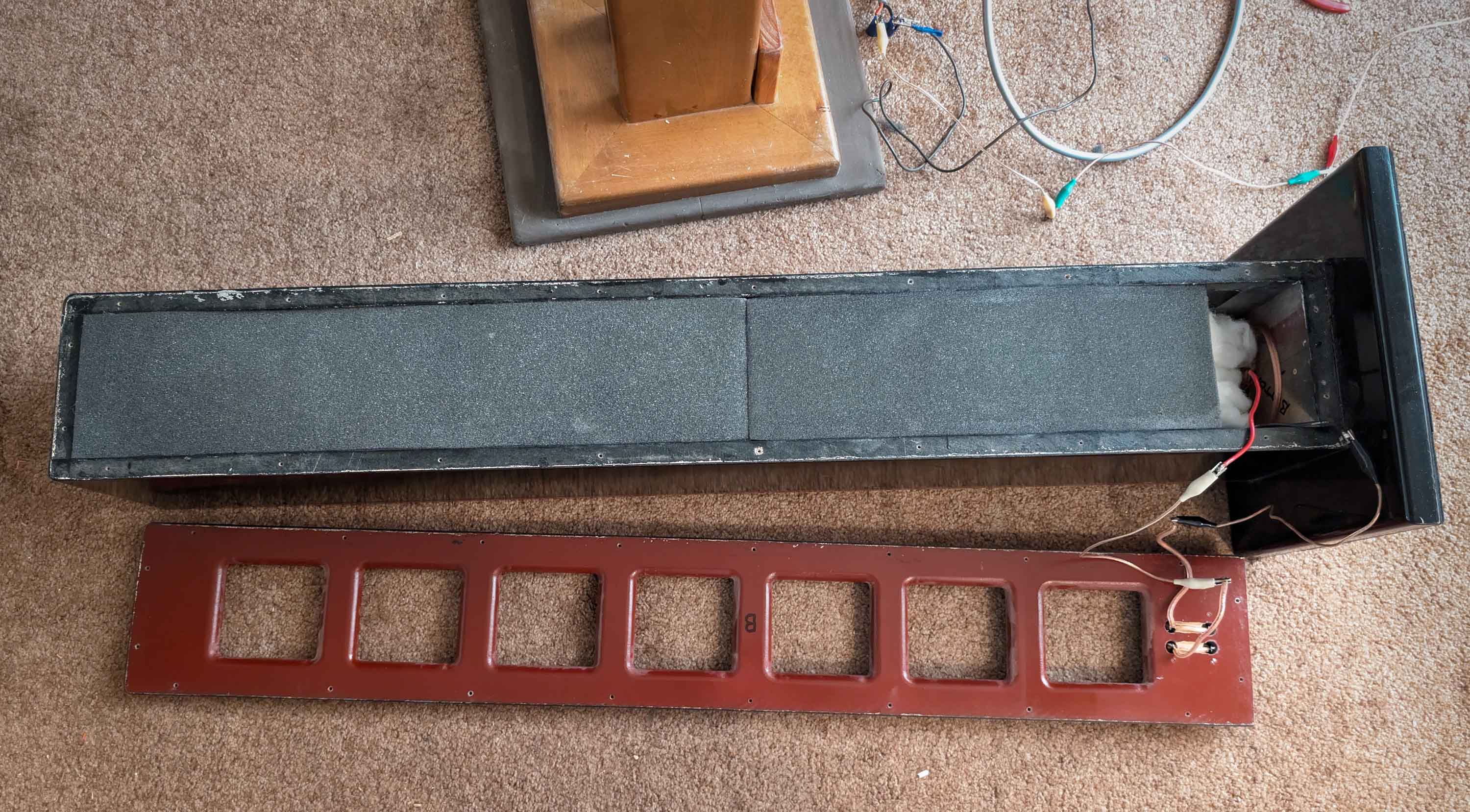
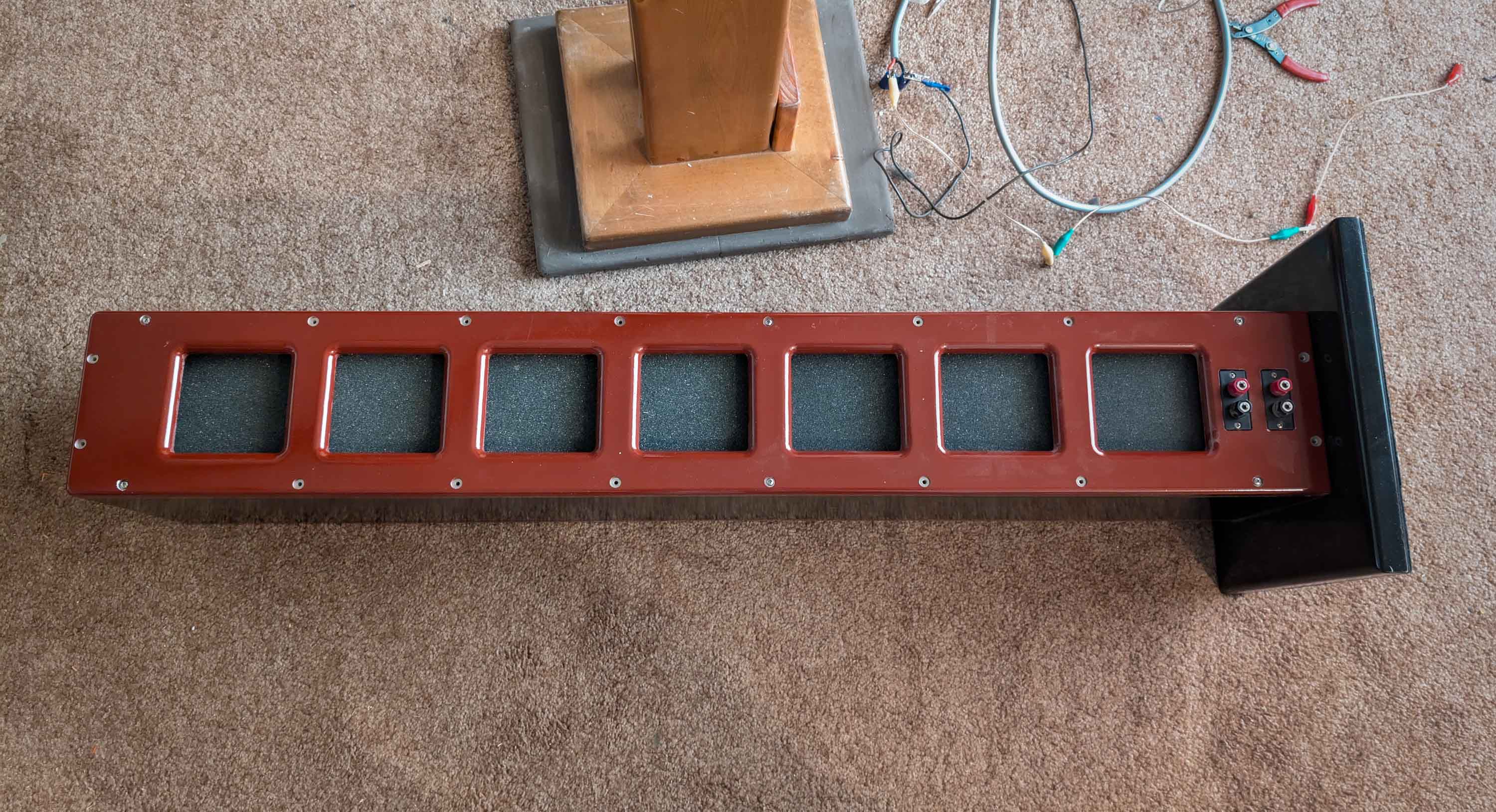
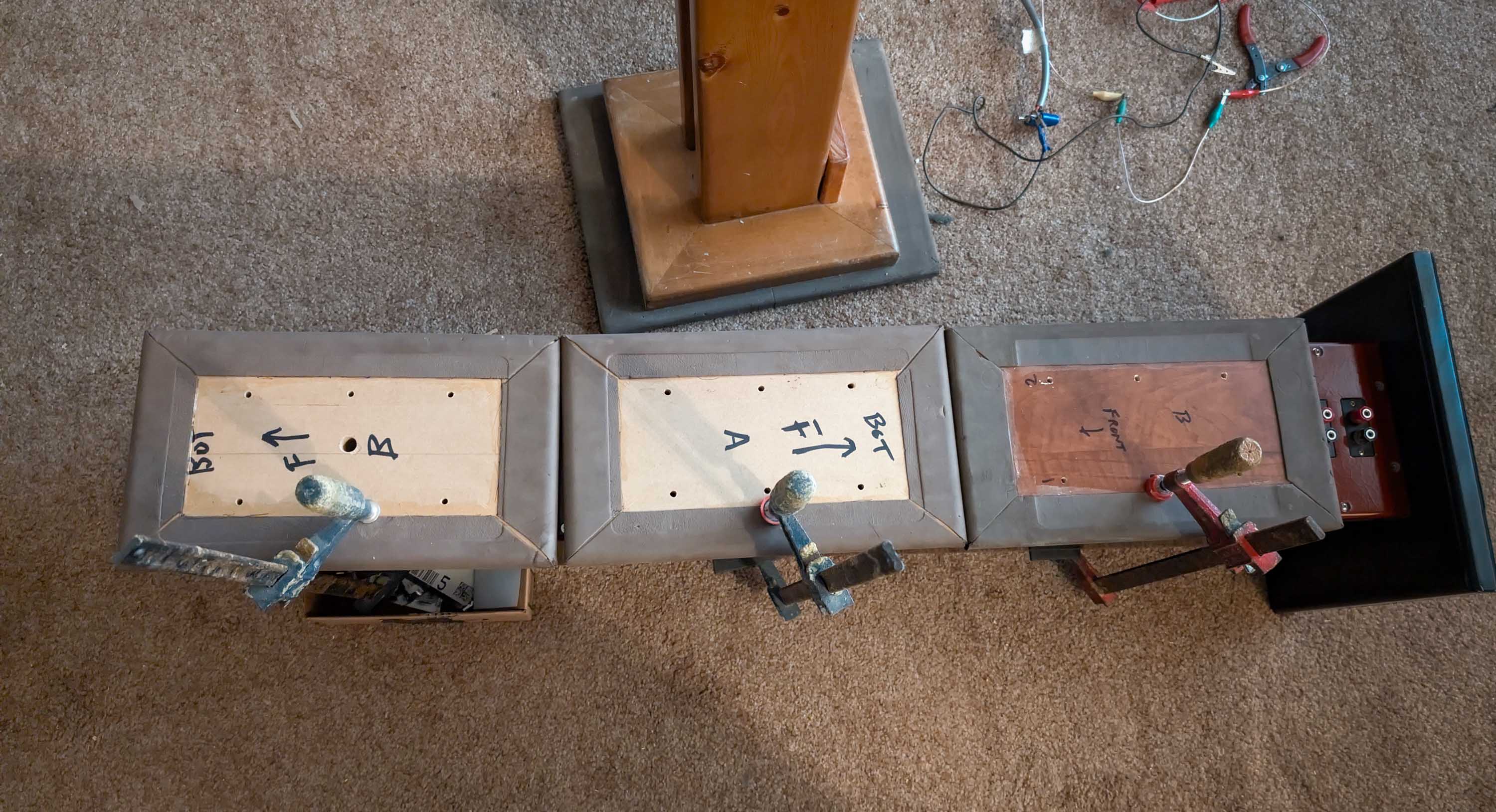
The brown curve is the same as above, except now the bottom 5 aperiodic vent holes have been sealed off by clamping plates over the holes (see pic). This moves the alignment closer to a closed box, which causes the SPL to increase near 200Hz.
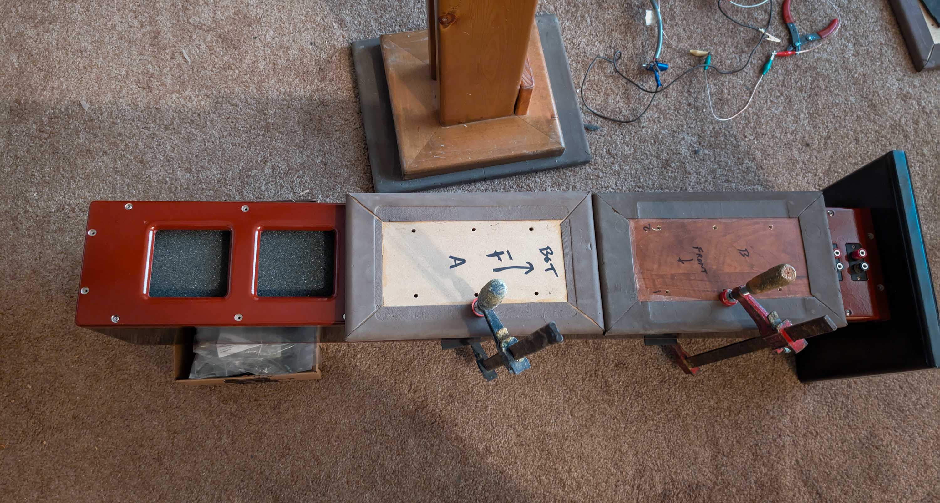
Finally, the green curve is the same as above, except now all 7 aperiodic vent holes have been sealed off by clamping plates over the holes (see pic). Again, this causes the SPL to increase more near 200Hz.
That is all I have time for right now. I’ll stop back tomorrow with additional info.
2 Likes
It is reusable, comes off very easily. It is like the Mortite caulking rope they sell at the hardware store for windows. When I removed the RD40’s from the cabinets several months ago, I rolled the caulking up into a large ball and saved it. It stays sticky to the touch and lasts for years and years.
1 Like
That black tacky stuff is called butyl tape. Commonly used to install windows.
2 Likes