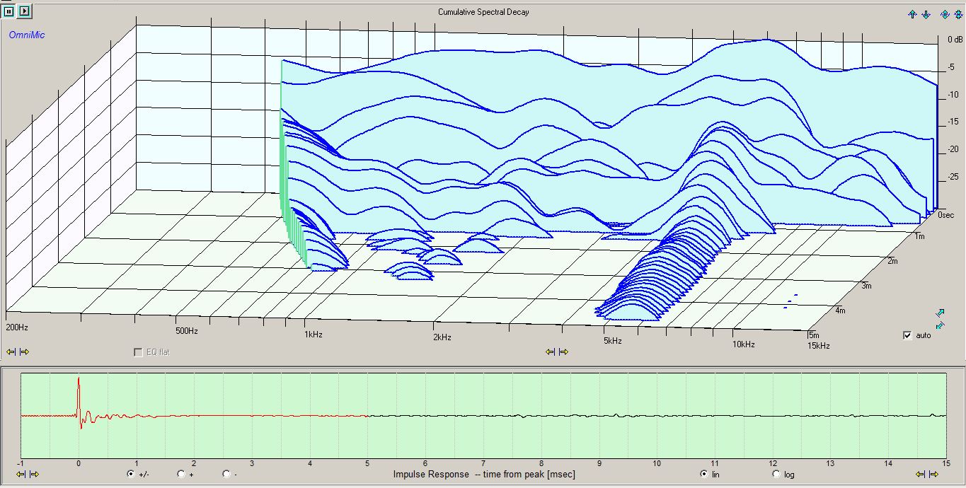
Here is a CSD plot of the RD40 mounted in the cabinet with Acousta-stuf and convoluted foam filling inside. No crossover parts or protection cap. No foam blockers up front. You can clearly see the ringing at 5 to 6kHz. This ringing does not show up at all on the impedance curve.
1 Like
Any guess about what’s causing that? You’ll be crossing before that anyway, right?
I have no idea. The engineers who designed the driver probably understand what is going on. I would be sticking my foot in my mouth with a guess. All I know is that this is something that I really need to suppress as much as possible. In my Plan-Tanic speakers from 2014, I had a filter that pulled the on-axis peak at 5kHz down by about 3-4dB or so. This was clearly not enough. I also need to look more closely at the overall power response this time around. I was not paying attention to power response in 2014.
Comments from all the judges at the 2014 MWAF seemed to be related to this problem as well. Here are a few quotes from my old score sheets: “Guitar notes have an extra ‘feathery’ edge that doesn’t sound right. Odd thin sound. Female vocals sound well defined and dynamic, sibilant though, not right, shame, otherwise quite expansive and engaging. Imaging unstable.”
“A little peak somewhere in the mid-highs. Slight honk sound.”
Other than the red open with no stuffing, the other 3 are very similar other than 200 hz, depending on where you are crossing.
That is my conclusion so far as well. Even if I were to change the type of stuffling, such as adding layers of 1" fiberglass interleaved with 1" layers of Acousta-stuf, this would only cause the SPL at 200Hz to shift up or down a little bit. The highest SPL at 200Hz would always be the completely sealed box version. The lowest SPL at 200Hz would be a version with all 7 aperiodic vents completely open.
I am leaning toward the completely sealed arrangement. This will give me the ability to cross as low at 150Hz. Per the Indy 4 octave rule, I could then use an upper xover as low as 2.4kHz. If I leave all 7 aperiodic vents open, I would then need to move the lower xover up to about 200Hz, which, in turn, would shift the upper xover up to 3.2kHz.
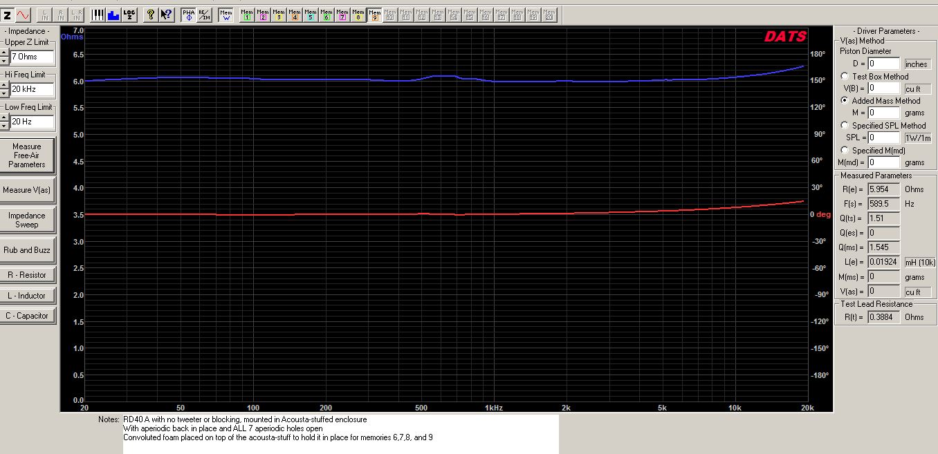
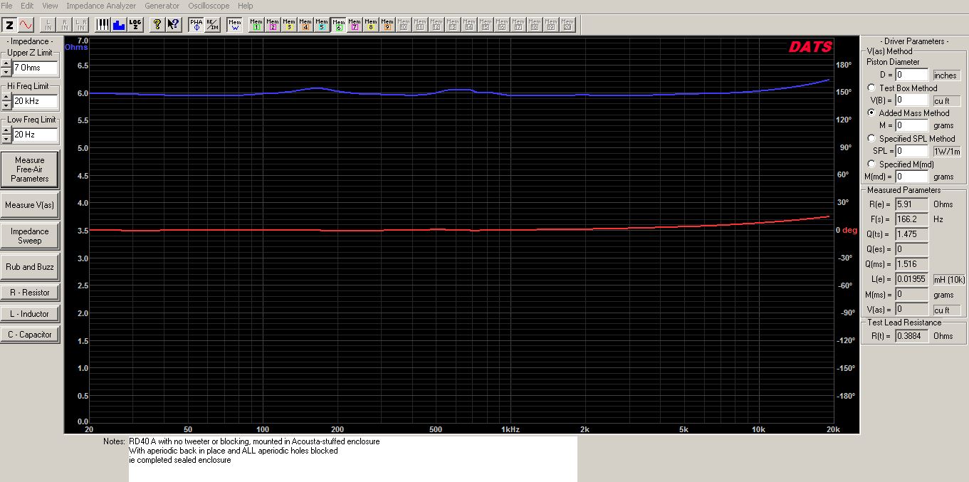
FYI, here are the impedance curves comparing the stuffed/sealed enclosure verses the stuffed/aperiodic enclosure. Both curves are basically flat lines at 6 ohms except for slight bumps here and there. The completely sealed version has a little bump around 175Hz related to the increased SPL at 200Hz. The small bump at about 600Hz is a little bit smaller for the completely sealed version. Neither version shows any bump in the 5 to 6kHz region.
Only thing I could think for the 5khz would be the metal mask plate ringing. Since there is an air gap it wouldn’t have great coupling to affect the element much.
This is from a BG data sheet.
“For optimum performance of the BG RD series drivers, it is recommended that a simple notch filter be installed. This notch filter corrects for cavity resonances between the magnet structure and the
diaphragm in the 5K to 6K range.”
3 Likes
Small magnet/diaphragm cavity resonance for the win!! ![]()
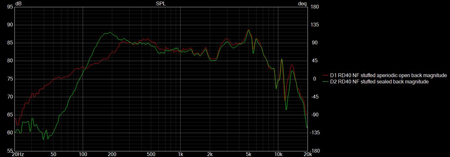
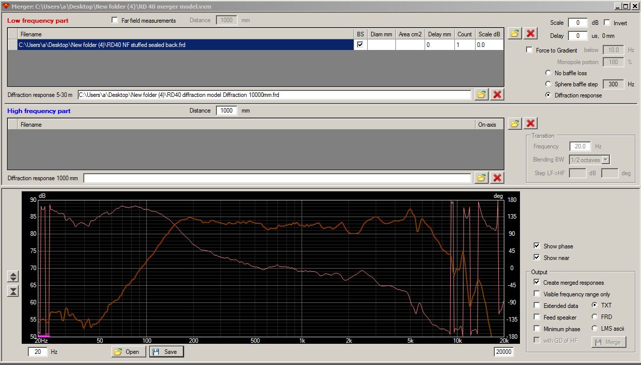
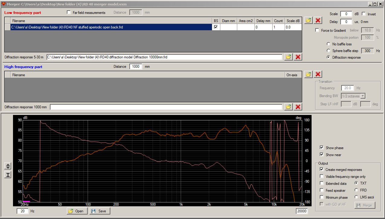
I did some NF measurements of the RD40 in the stuffed sealed cabinet verses the stuffed aperiodic open cabinet configurations. I was not sure how to do a NF measurement on a driver that is 35.5" long, but it seemed to work OK. Mic tip was about 1/4" above the center of the diaphragm. The sealed back NF measurement has an inverse baffle step slope that flattens out perfectly when I apply the diffraction correction model. A 150Hz xover looks like it will work very well with this configuration. The aperiodic configuration, OTOH, drops off quickly below 300Hz and would need an xover of about 250Hz or so. So I think I am going to drop the entire aperiodic idea and seal the back. Probably glue a long board over the vent holes from the inside so that I do not have to re-do the entire back panel.
Hey Bill, can you please elaborate / explain this statement please. I am not sure what you did or are doing.
I’ll try to explain as best I can. The green curve in post #90 above is a near field (NF) measurement of the sealed back RD40 configuration. NF measurements are generally accurate below 500Hz or so, but they do NOT include low frequency stepping losses created by a thin baffle board. So, I created a diffraction model of my 41x6.5" baffle board using VituixCAD’s diffraction tool. I then imported this diffraction model and the NF measurement into VituixCAD’s merger tool, and added the two curves together. The result is a corrected curve that accounts for the full 6dB of baffle stepping loss created by my very thin baffle board.
The green curve in post #90 above slopes downward from a high of about 87.5dB at 175Hz to a low of 83dB at about 1kHz. This is what I meant by the NF measurement having an inverse baffle step slope. Usually, this is not the case. Usually, the NF measurement has no slope and when you apply the diffraction model, the curve usually has less SPL in the 100 to 200Hz region. But that is not the case here. Hope this helps.
Thanks Bill makes sense. Does this mean you don’t need BSC,as the green curve after diffraction doesn’t seem to drop down?
Yes. Assuming, of course, that my NF measurement technique is accurate for a ribbon driver that measures 1.5" wide x 35.5" long. I measured at a 1/4" distance from the center of the RD40 with the gating turned off. After taking the initial measurement, I moved the microphone back slowly and watched the OmniMic screen during the whoop whoop process. The measurement is very consistent with my far field (FF) 1 meter measurement. As I move the microphone further and further away the curve begins to develop reflection ripples at the lower frequencies. But the overall shape of the curve remains roughtly the same at the 1 meter distance.
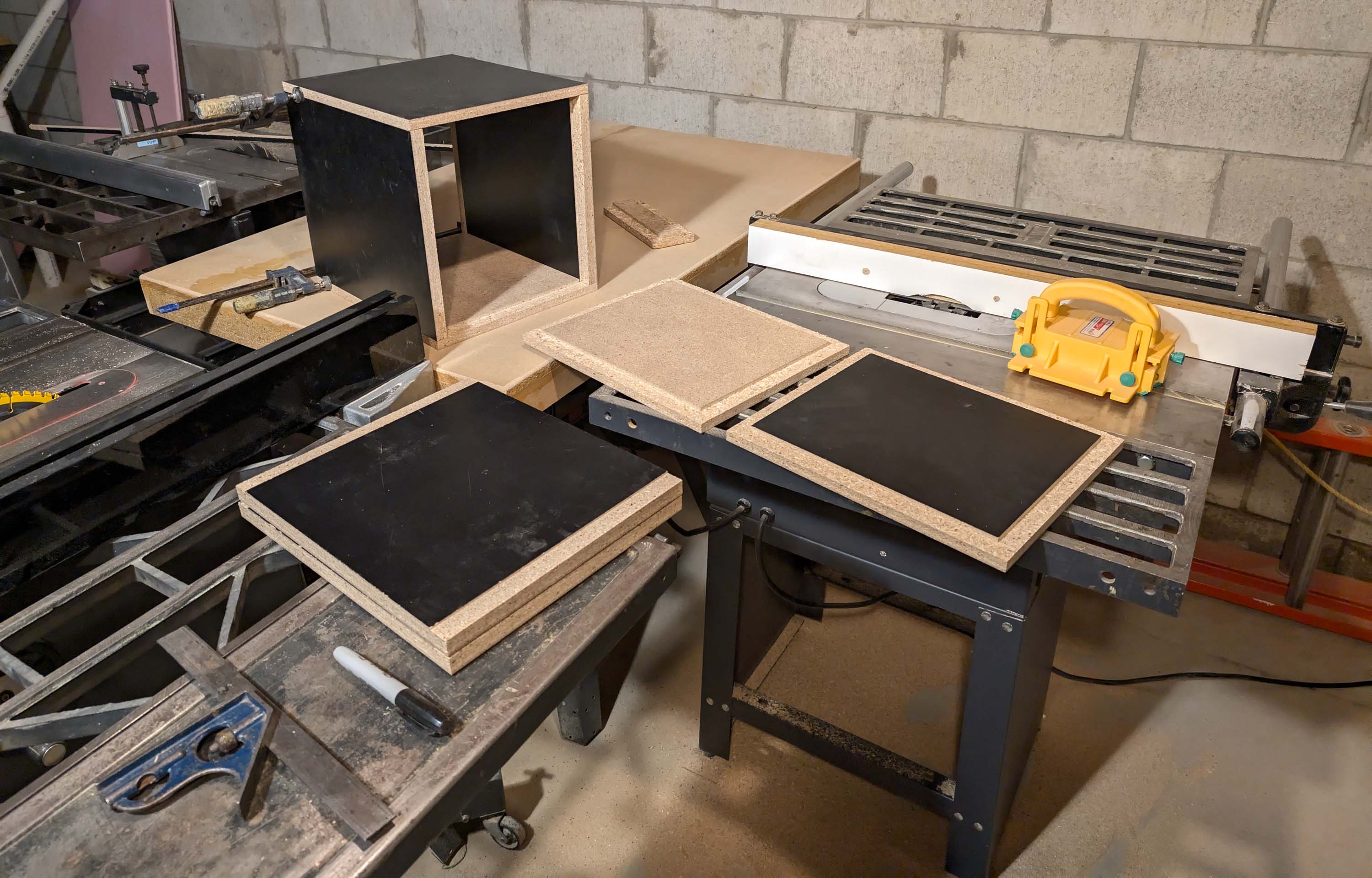
Time will tell if these measurements are accurate. I’m firing up my table saw today to start making the bass bins for the Esoteric 7" woofers. Then I will take some more measurements to see if I can get them to blend well at 150Hz with the RD40’s in my VituixCAD model.
1 Like
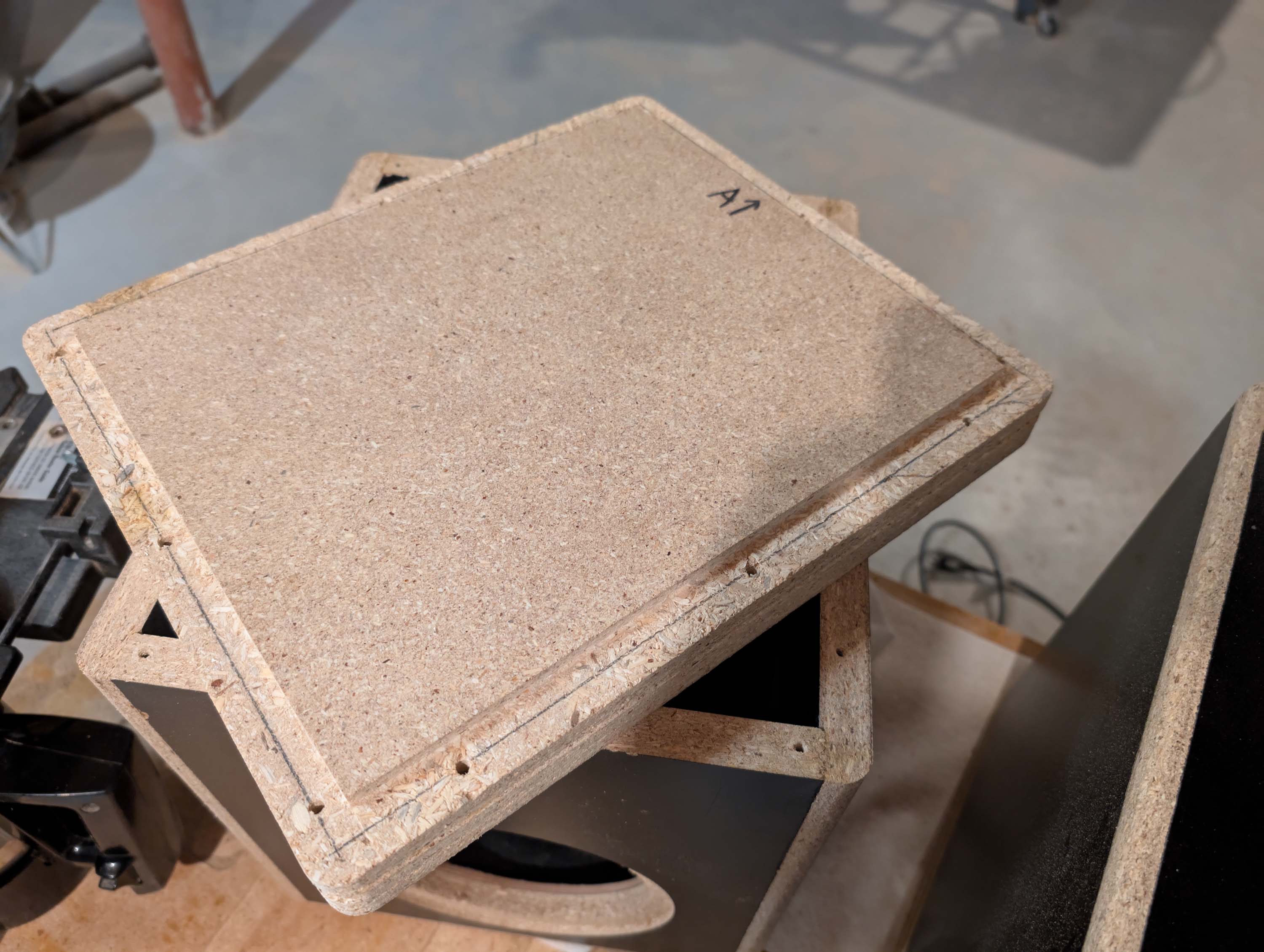
Today I started building the bass bins using my cheapy red tag $1.00 Menards’s value shelving. They will be small 0.75 cu.ft. boxes tuned to 32 Hz using a single 7" esoteric woofer in each bass bin. Yellow wood glue does not stick well to laminated cabinet surfaces, so I’m cutting a dado along most of the joints. I went with a 1/4" deep dado on the tops and bottoms and a 1/8" deep dado on the side panels. The bottom panel is just regular unlaminated 3/4" particle board, but I cut a dado along each outside edge of those panels as well, just to be consistent. The dados will also help to register and hold the panels in place during the glue up process.
2 Likes
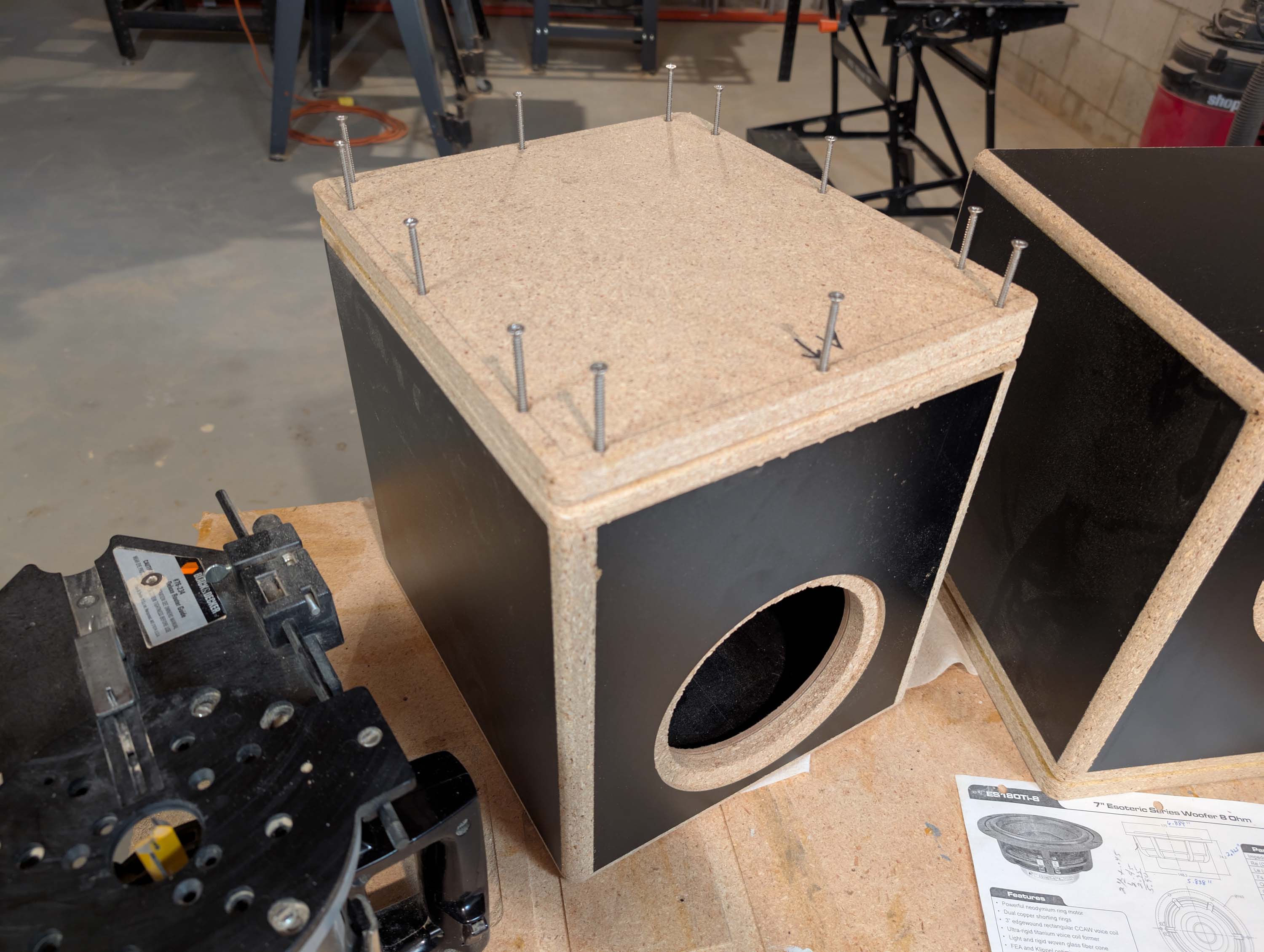
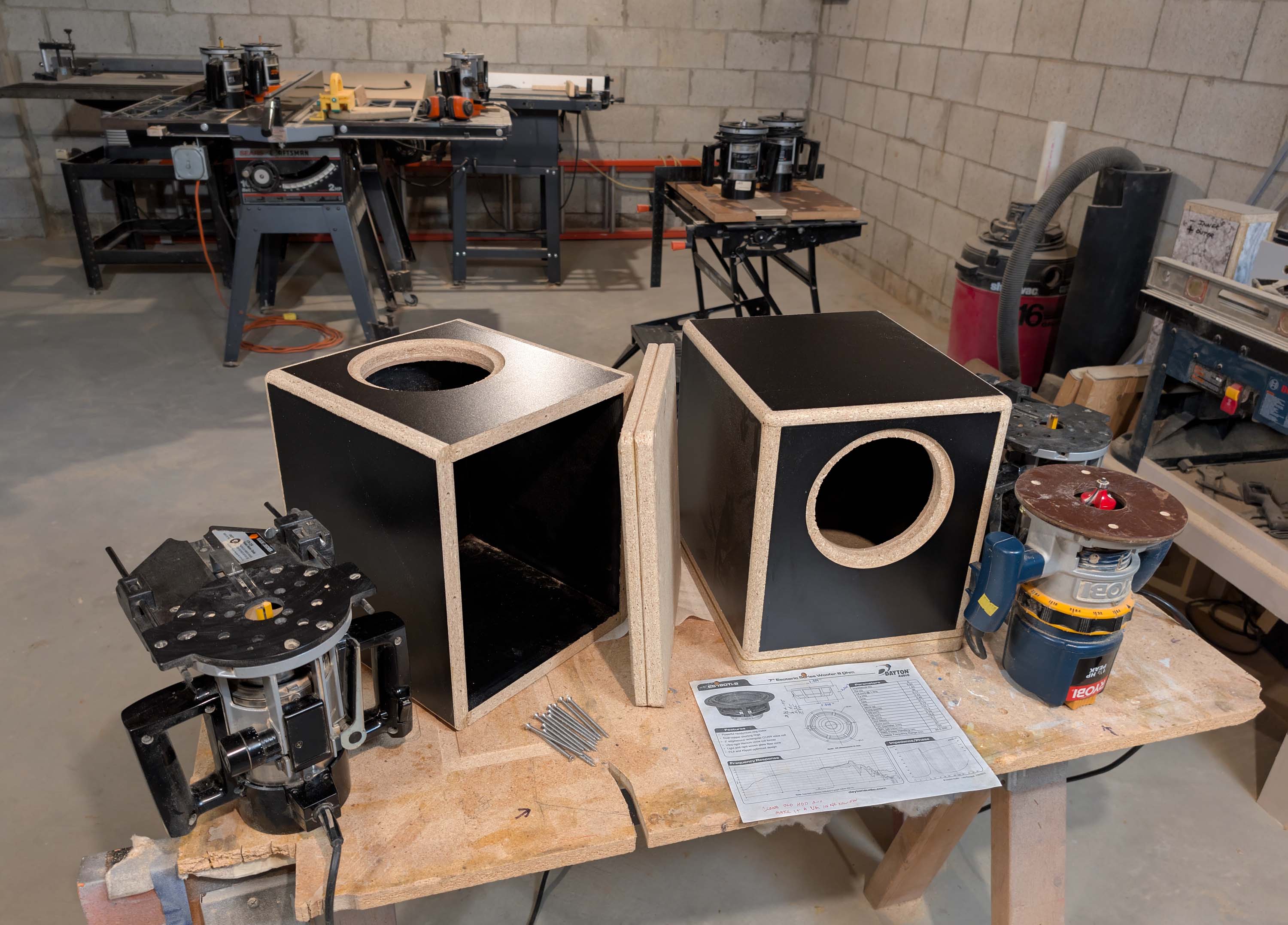
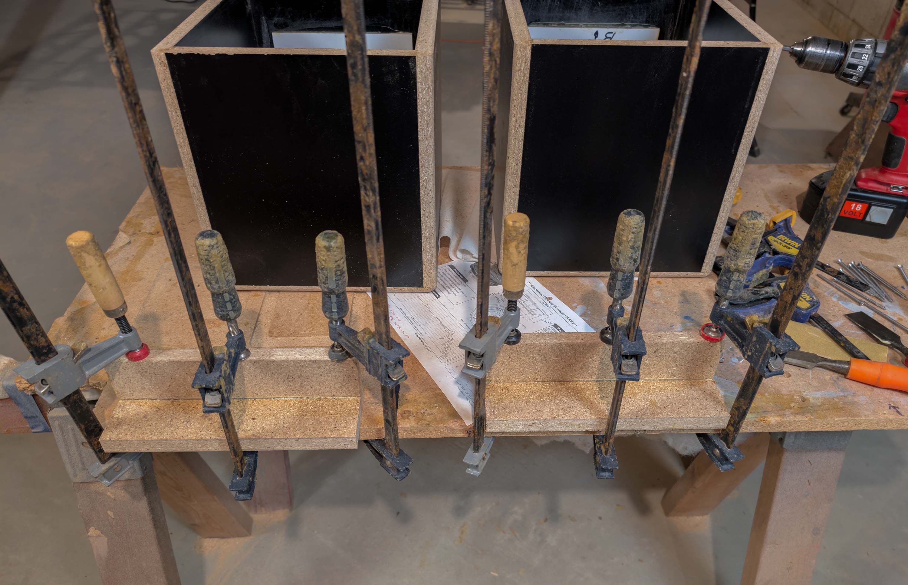
Progress report: Bass bin boxes are glued up. I increased the thickness of the bottom panel to 1.5" and made it removable with twelve #8 x 3" screws. I increased the baffle thickness from 0.75 to 0.95" to make up for the 7/32 flange recess. Next I’ll be cutting a hole for the bass reflex ports. They will be 2.1" x 2.1" x approx 9" to 10" long rectangular ports going along one of the two top corners. The removable bottom will make it easy to tune them to 32Hz.
3 Likes
Gluing up bass reflex ports from Menard’s value shelving. Total cost of about $0.62 for both ports. Doesn’t get any cheaper than that!
1 Like
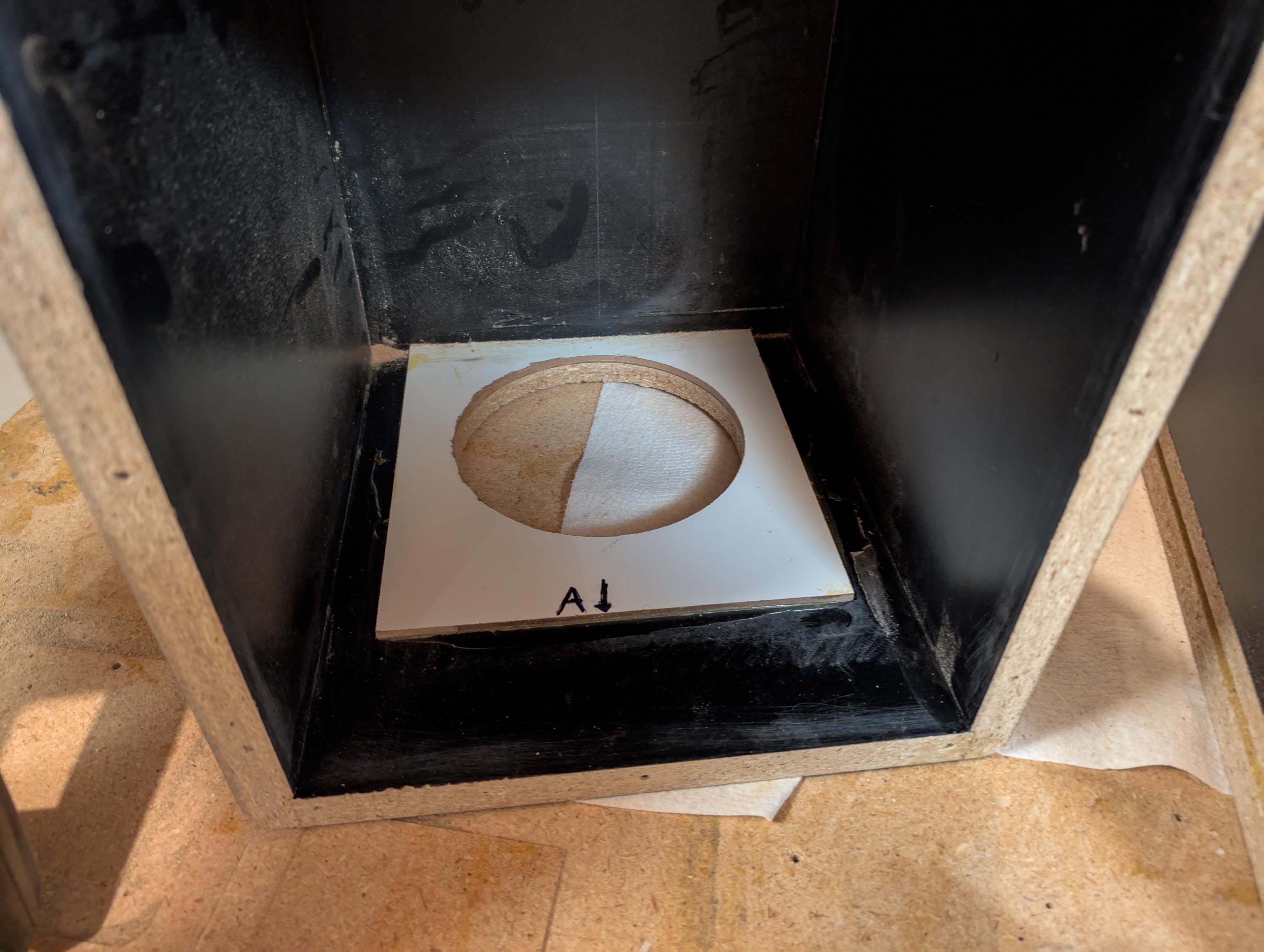
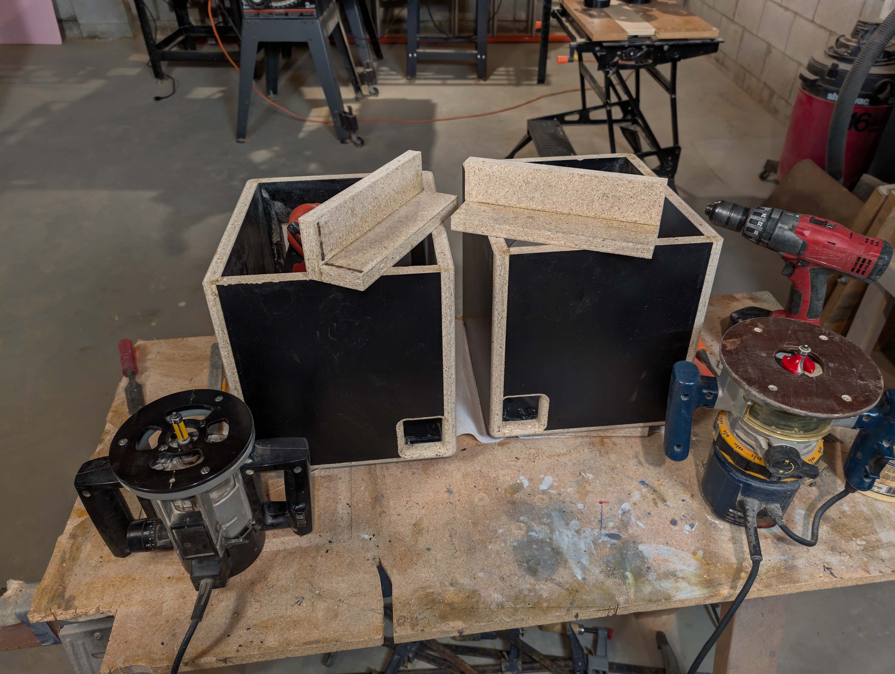
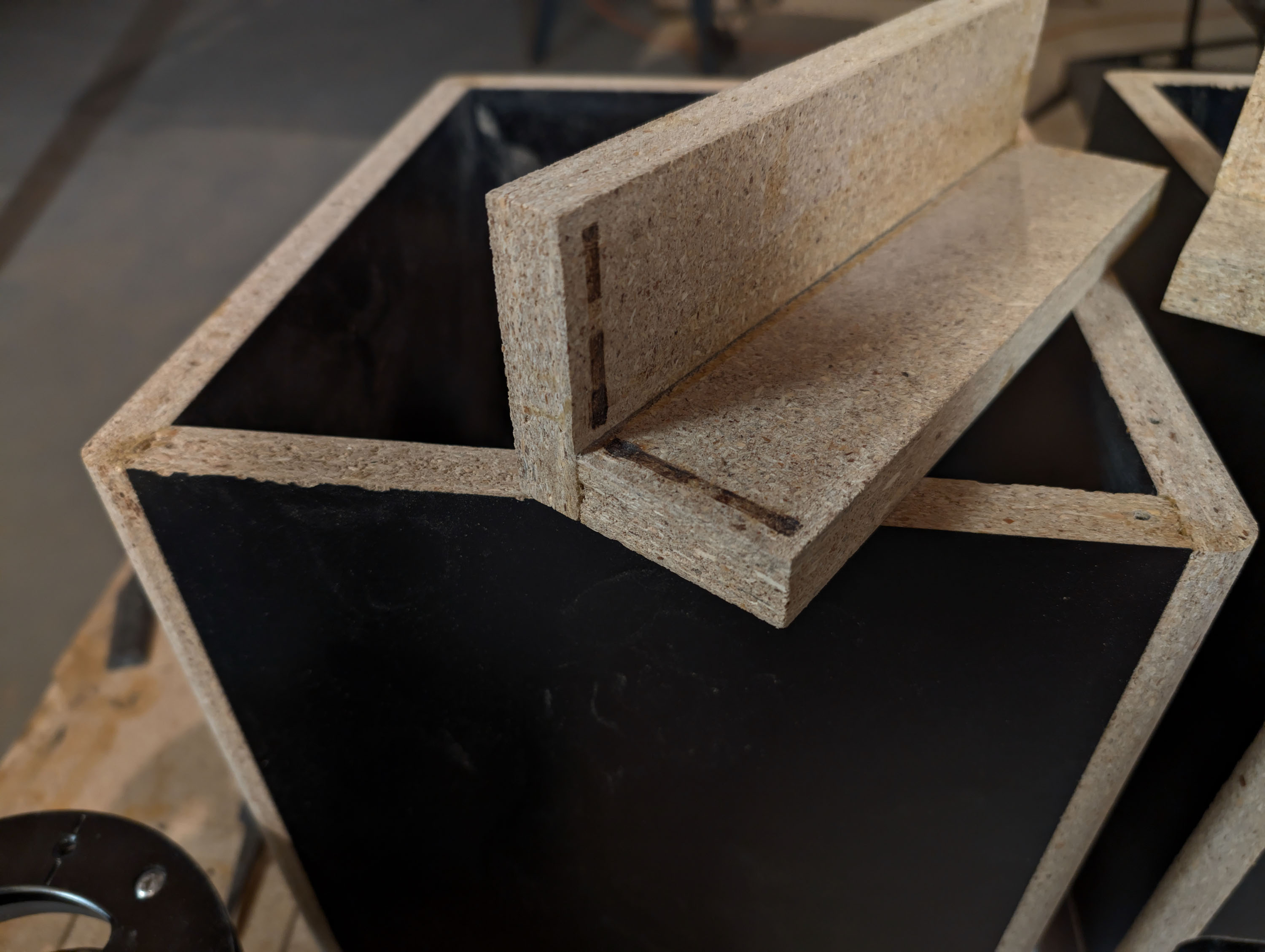
Today I cut the holes for the rectangular ports. To do this, I temporarily clamped the ports into position internally. Then I used my jig saw to remove most of the material, staying away from the line to avoid hitting the internal port. Finally, I cleaned up the holes with my flush trim bit.
As you can see in the 2nd photo, the bearing on the flush trim bit froze solid and burned/gouged the inside edges on one of the two ports. This is the now the 2nd time I’ve had to replace the router bearing on a flush trim bit. ![]() After replacing the bearing and finishing both holes, I rounded the port edges with a 1/2" roundover bit. This should clean up easily with a little sand paper and wood filler.
After replacing the bearing and finishing both holes, I rounded the port edges with a 1/2" roundover bit. This should clean up easily with a little sand paper and wood filler.
What type of glue do you use to bond to the melamine coating?
The melamine coating was already glued to the shelves when I bought them. It seems to be fairly durable and is holding up pretty good so far. Sometimes when I buy this “value shelving” from Menard’s, the coating will actually start flaking off due to a bad glue job. So far, so good.
I rounded all the box edges with a 1/2" roundover bit and my future plan is to bondo, sand, and then paint the edges black (or another contrasting color) to blend with the black melamine coating.