A 4 ohm mid makes for a difficult 3-way

At least, it seems like it did this time. LOL

So, my good friend @Stearns250 and I have been collaborating on his build. GRS PT2522C, SB12MNRX2-25-04, and a pair of SIG225-4s in series. Jeff’s been building and taking measurements in God’s frying pan Arizona and I’ve been coaching from The Frozen Tundra.

Measurements were taken at 2m on a ladder, so ground bounce wasn’t too much of an issue but logistics of the day didn’t allow the full spin-o-rama of off-axis measurements. Acoustic offsets were derived by Mr. Bagby’s A/B/A+B method. Baffle losses are definitely in the woofer measurement (which was taken with both drivers connected in series). That valley in the tweeter response is real, and does not appear to change behavior off axis. At least it’s narrow.

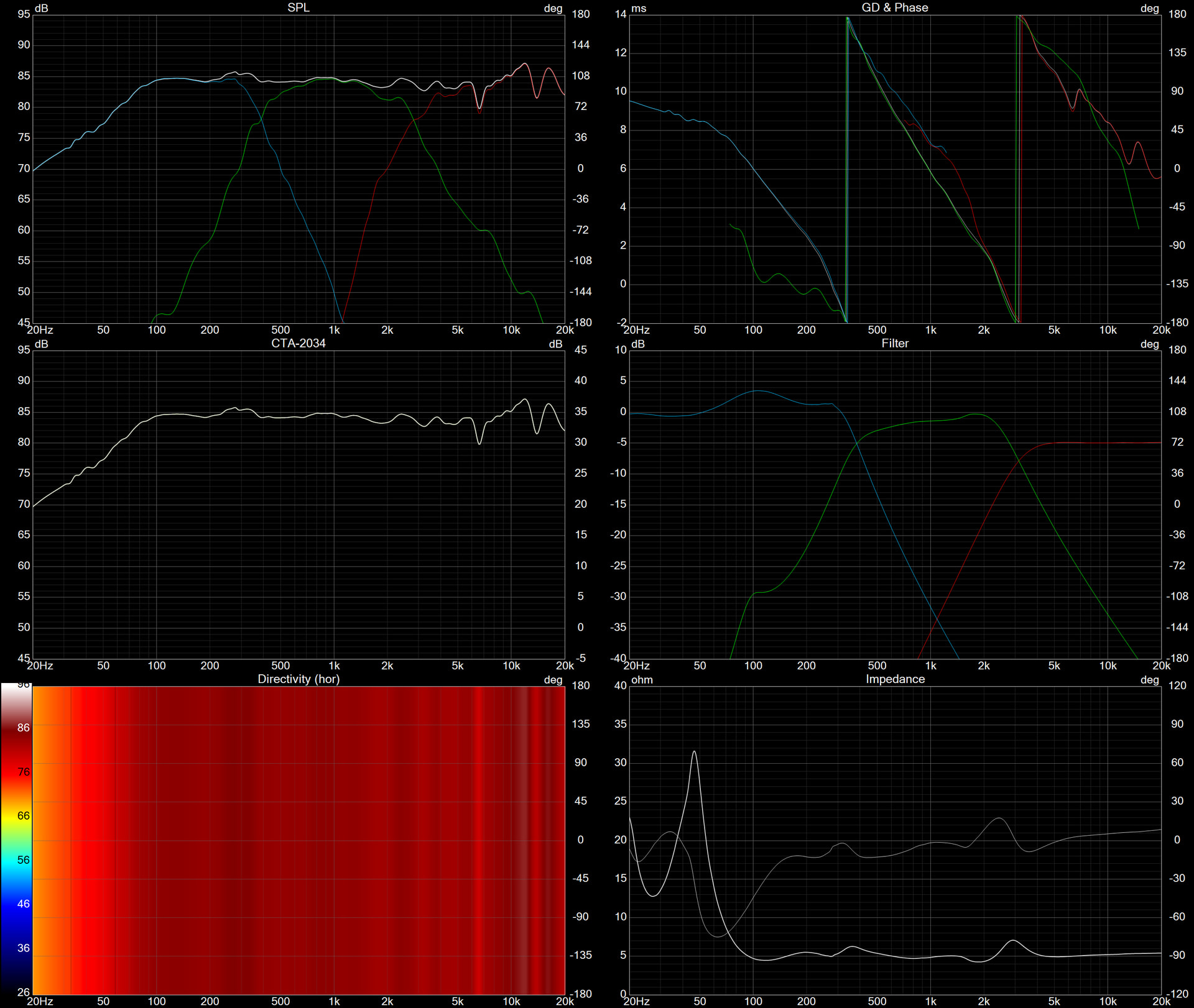
But I’ve got my doubts on the crossover here. First, the broad strokes:

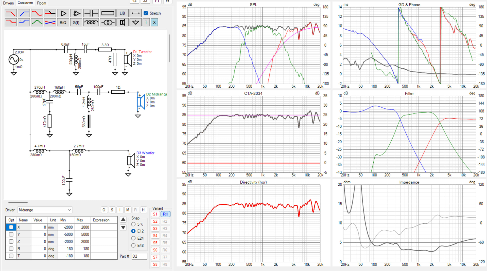
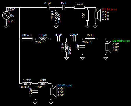
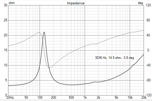
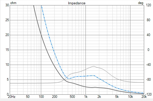
Phase tracking of our crossover design is really good. We’ve tried multiple times to raise the impedance, though, and this is about the best state that can be achieved. It’s basically 3 ohms over most of the midrange. I don’t know why I’m surprised, I guess. Shape of the upper octave is easy to tweak by re-enabling the shunt resistor and rebalancing the L-Pad. We also tried bypassing the series resistor with a small coil as a means of tilting the tweeter’s response downward, and I guess we still can though I’m not sure the juice is worth the squeeze.

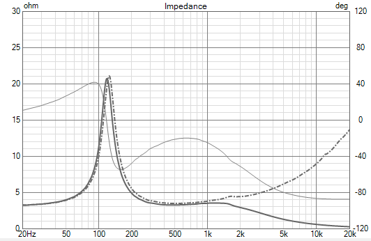
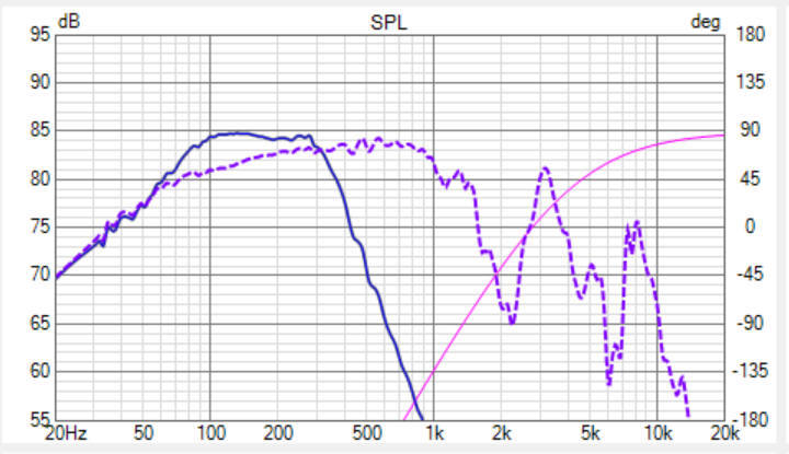
My main concern is the lowpass. Purple dash is the unfiltered raw woofer response. The shunt cap is interacting with the woofer’s upper impedance peak and creating a heaping helping of gain.

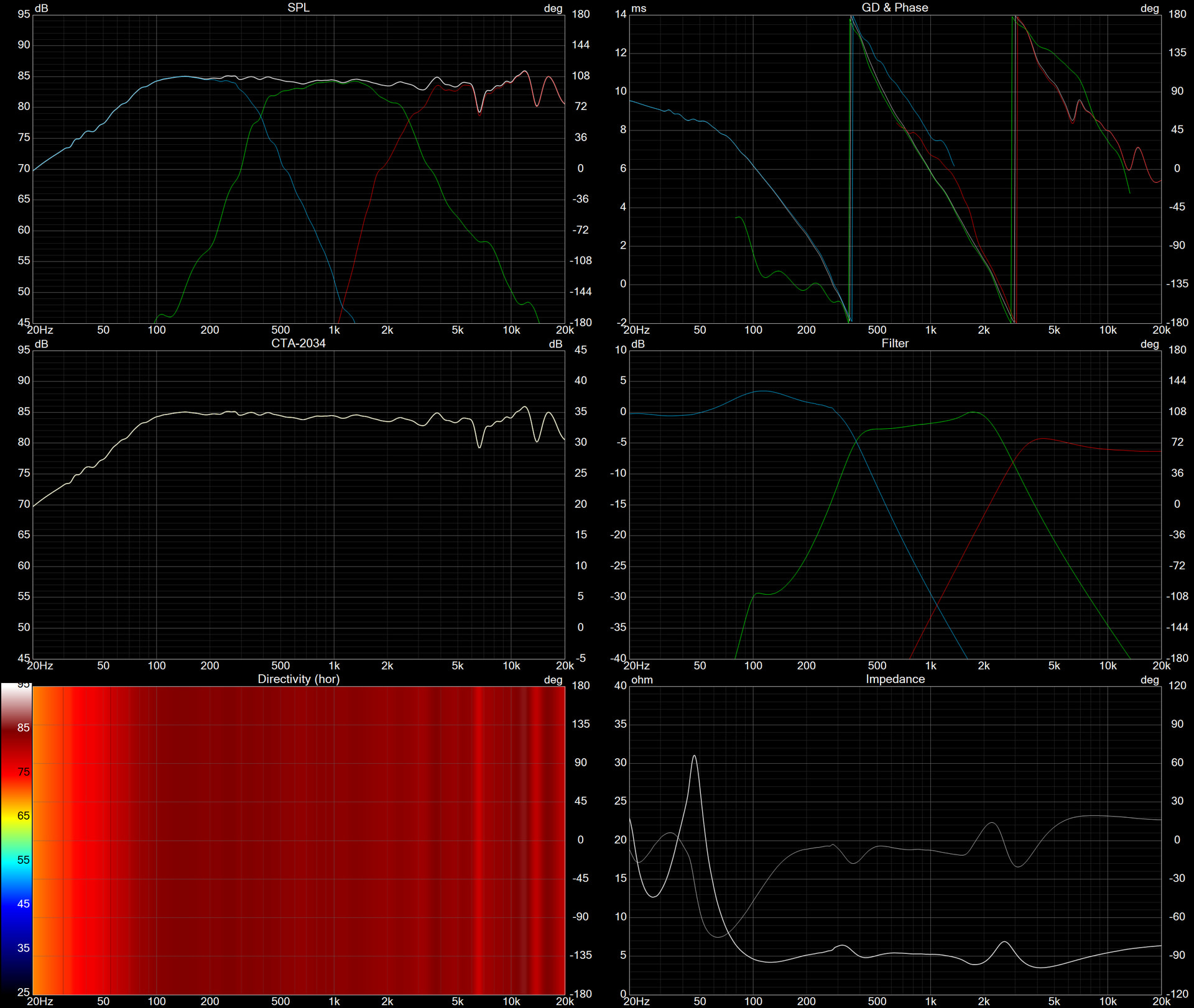
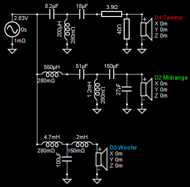
I may be overthinking this, but will that added gain on the low end prove too much, and too tubby? Sure, that measurement shows the baffle step losses, and our final crossover topology certainly looks workable, but I do worry that I’m misinterpreting what the data says, or we’re going about this in the wrong way, trying to use traditional topologies. I did mess around with a high-Z resistor in parallel with the woofers, and that did lessen the knee in the filter response, but by the time I refactored the other crossover elements…the same basic filter shape returned.

It’s been a long while since I did a big 3-way (those curve-sided merlot beasts with the silver flute woofers), and circumstances with that one were such that I ended up ear-tweaking a LOT to get the low end right, and I would prefer we not have to repeat that here.

So what do we think? Ego is set aside here. Thy breast is bare. Stab away.

Should anyone want to take a crack at it, I’ve bundled up the Vituix file with the FRDs/ZMAs:

(you’ll of course need to adjust the paths to each of the data files on first load of the .VXP)

In the following I set SMOOTHING in the Drivers settings to 1/12th octave for the tweeter and woofer and 1/6th octave for the midrange as it looked like there were some reflections in the measurements.

TEST 1: I moved your 27uF shunt capacitor on the midrange to the right of some of the other components and tweaked other components to match your original response as close as possible. Minimum impedance is briefly 4.4ohms around 1.9kHz. (I don’t think the 30 ohm shunt resistor is needed.)

TEST 2: I used the optimizer to aim for a flat on-axis response and tweaked some components to match readily available component values.

6 Likes

Thank you for looking at it. Why would moving that 27uf cap change the ohms?

It’s a different nodal connection, so it can change.

1 Like

That is both subtle and excellent, @a4eaudio

1 Like

The behavior of any given crossover component depends on the impedance of the load. Put another way, the order in which you stack up your parts can matter. For example, here’s the raw impedance of your mid:

Now, here’s the impedance of your mid with a 27uF cap in parallel with it:

And that is the impedance your 3rd order highpass has to work with. And then the 3rd order highpass will alter the impedance further, and then that is the total impedance that the lowpass will be asked to work upon. Here’s the impedance with the highpass in place, and the 27uF cap in the old location (black trace) and the new location (blue dash):

Ultimately, this is the load that the .5mh lowpass coil must work with. Black and dash-blue will make for different responses in our 300-500hz crossover region. Even though that cap is part of the lowpass filter, it impacts the behavior of the whole midrange. And is a big cause of our impedance issues.

That’s the best I can explain it. Haha

This ALSO means that it’s possible to get different results if you lay out your highpass first and lowpass second, or other way around, changing the way the filters react with each other. This sort of stuff is one of the reasons why 3-ways are harder than 2-ways. There’s SO much happening through the midrange.

6 Likes

Thank you for the explanation, I think I understand. I will have to model some stuff to really understand it. I appreciate all the help!

It is fun stuff, rearranging components in Vcad. It seems that textbook filter examples are just a starting point.

2 Likes

Excellent analysis! I struggle with low impedance problems with my 3 way builds almost every time. Thanks for sharing. :+1:

1 Like

I tried a whole bunch of weird filters. Even laid out a whole dang series crossover, but it was about the same with worse phase. Never considered moving the cap tho. Ha

1 Like