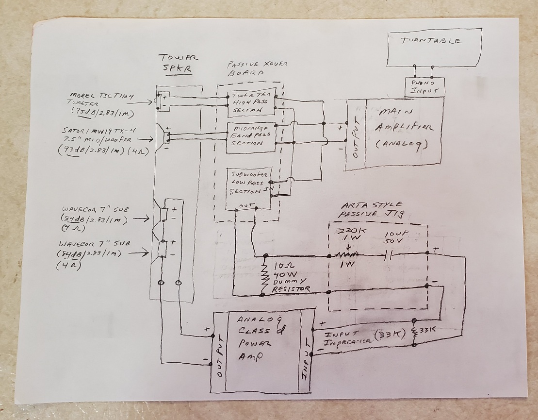
Block diagram. I added a turntable before the main amp in keeping with the analog theme.
1 Like
It will indeed. I’m using 10 ohm, 40W on my diagram. 5 watts may not be enough here.
I noticed you used a 560k dropping resistor while I used 220k. I’m just guessing at this as a starting value. You will want to set this value as high as you can, yet still have enough gain to blend the subwoofer output SPL with the mids and tweeter.
I added a 10uF 50V protection cap at the input to the class d amp. This is to remove any DC offset that may be present at the speaker level outputs of your main amp. If your class d amp has a blocking capacitor at its input, then you can eliminate this cap. Also, you should be able to reduce this value from 10uF down to 5uF (or even 1uF) with no problem. The half power point of a 10uF cap driving into a 33k load is 0.48Hz. Half power for 5uF driving into 33k is 0.96Hz. 1uF is 4.8Hz. (1/(2piRC))
Thanks Bill. I checked the specs on my amp. bd. and gain is 28-32 Db. So I changed the voltage dropping resistor to 200K for approx 10 db of gain
volume pot for adjustability?
1 Like
That should work. As long as you always remember to set the volume pot at a high enough resistance to prevent input overload. Once you determine what value of total resistance is needed, maybe break it out as a fixed resistor in series with an adjustable pot. For instance, if you need 200K total, break it out as a 150k fixed resistor in series with a 100k adjustable pot.
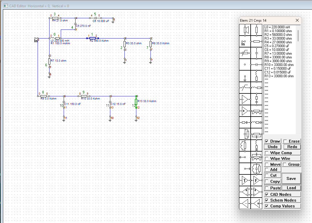
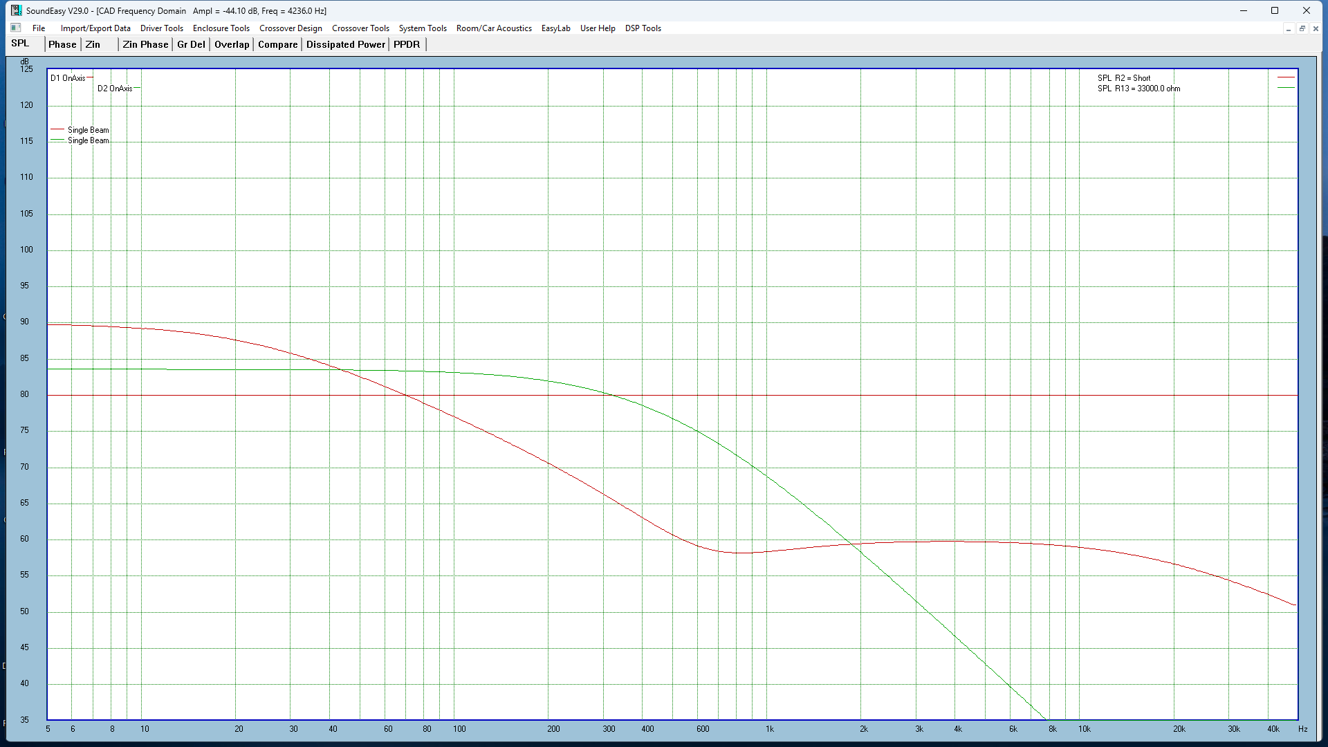
I entered Eggguy’s woofer crossover into SoundEasy and plotted it’s response. I had to short the 550K resistor in order to plot the output. I then used the link supplied by DrewBrews to design a 2nd order 350Hz line level low pass.
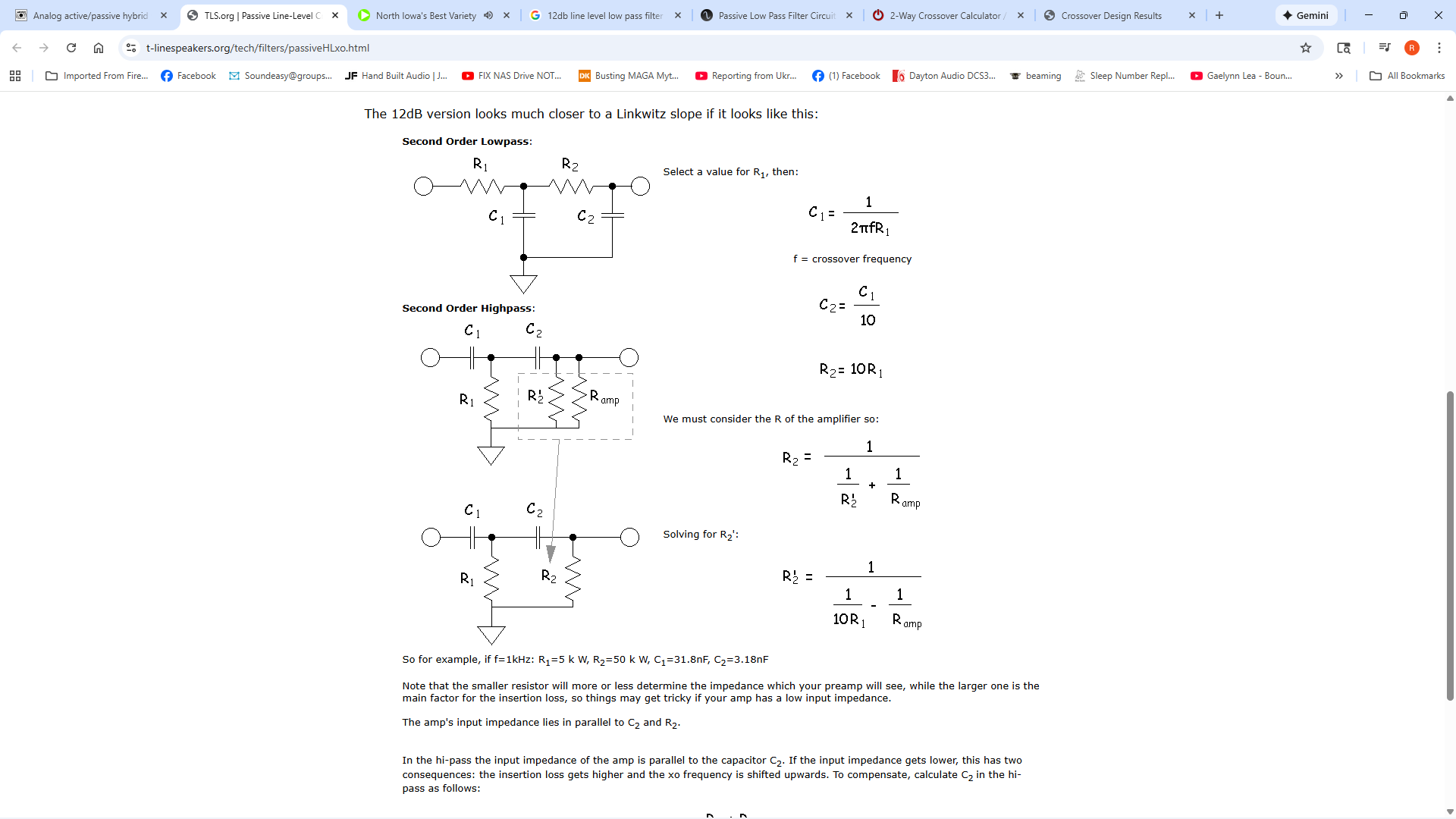
Red is Eggguys crossover with a 33K load. Green is line level low pass.
You would need to use a voltage divider to limit the output.
I hope this isn’t crazy. It’s been a long time since I’ve done any electronics design.
For anyone wanting to roll there own op-amp filters I recommend the Active Filter Cookbook by Don Lancaster. There’s a PDF version. PDF Ebay has a number of used copies for not too much money.
Ron,
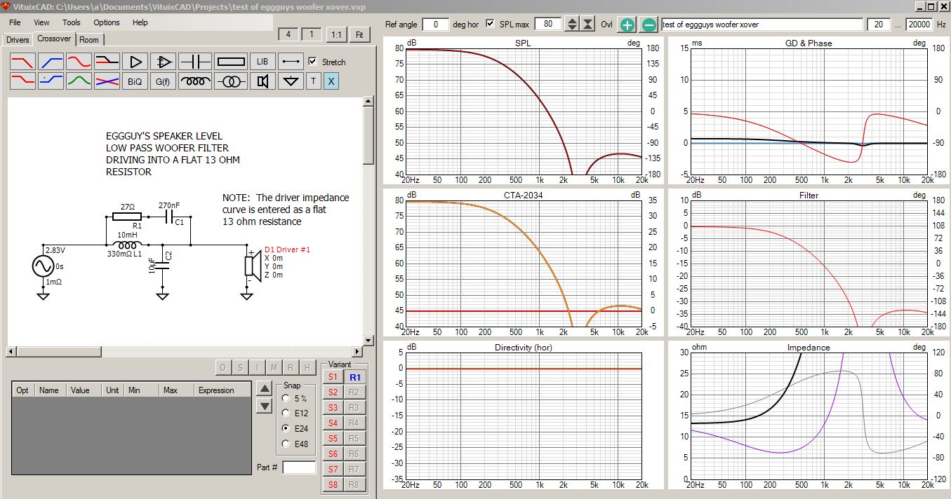
I entered @Eggguy,s woofer crossover filter in VituixCAD. It looks quite a bit different compared to your red curve. Correct me if I am wrong, but it is my understanding that the 33K + 560K (or 220K) impedances/resistances are effectively in parallel with the 13 ohm resistor, so the total effective load on the passive filter will always be about 13 ohms or slightly less, not 33k ohms.
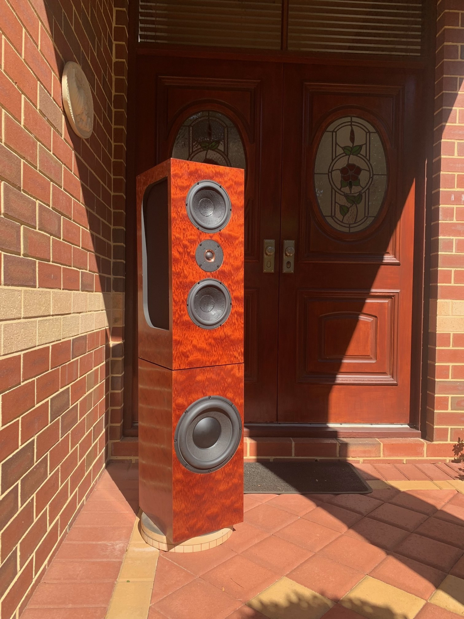
The subwoofers have an aluminum cone so I wanted to attenuate that first breakup by 40-50 db.
1 Like
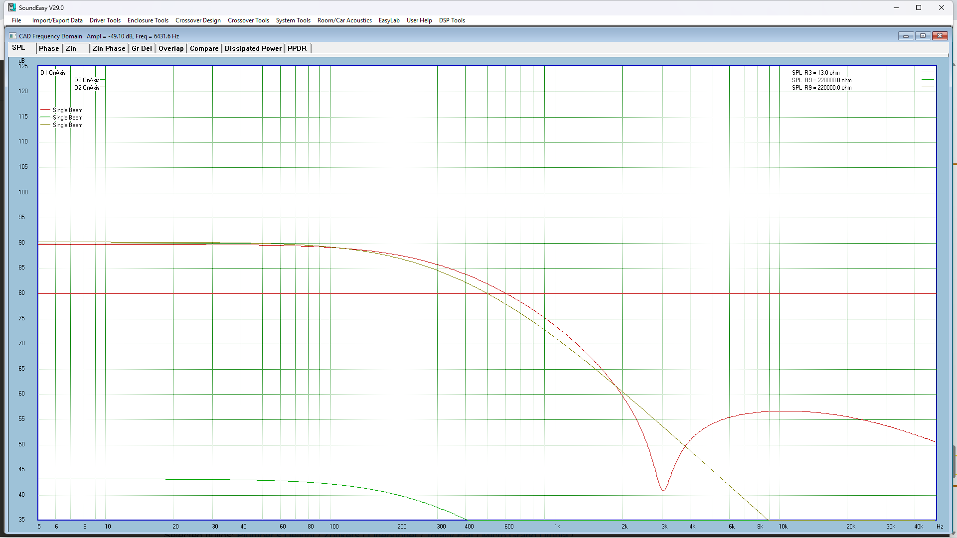
There were mistakes in how I interpreted and input his schematic. When I entered your schematic and values I got about the same results which are very close to the line level filter I designed.
Ron
1 Like
I built John Krevskovsky’s NaO speaker about 2 decades ago, in hybrid form, as a cost saving measure (only 2 stereo amps are needed for a pair of speakers)
Proponents or opponents of passive, or active crossovers seem to fire shots at each other.
But the hybrid approach that John employed has unique active attributes that neither passive, or nor active, alone, can offer:
a) passive crossovers can suppress resonances AND their harmonic distortion (notch filters in series)
b) active allows adjustable equalization for speaker placement.
other benefits, from a technical viewpoint here:
5 Likes