This will be a thread to discuss old school active analog crossover networks, as opposed to the newer digital types (dsp, etc.) This will include the use of stand alone analog plate amplifiers as well as active filters placed between preamps and power amps. This will also include the use of software programs, such as VituixCAD, to develop analog active filter networks. Most of the discussion will probably center around using a passive network for the upper xover and an active analog network for the lower xover (non-digital hybrid loudspeakers).
1 Like
Active filtering has a couple advantages in such a system. The driver impedance vs frequency doesn’t matter. I build using all-active crossovers, and I never need to worry about the impedance or bother to measure it. It can be a bit liberating. OTOH not everyone wants to dedicate 2N amplifier channels to your N-way loudspeaker. Since passive crossovers are relatively affordable and effective at higher frequencies, the hybrid approach is definitely of merit. Related to that is a 2.1 system with a sub crossover frequency around 80-120 Hz with a small 2-way.
The next advantage of the hybrid approach is that the active portion is quickly adjustable. One way to make good use of this is to allow the baffle step compensation EQ to be adjustable as needed, so that the speaker can be voiced in that region to suit one’s taste for midbass “color” in the overall tonal balance. This can be achieved using a couple of potentiometers and a very simple shelving circuit where center frequency and overall gain/loss across the EQ step are adjustable. Then the builder only need to worry about flattening the 1k-3k region of the baffle step and the crossover network to the tweeter. The response can be left to droop at lower frequencies through the baffle step region, and then the active circuit takes care of that.
And of course an active crossover at LF is relatively practical and higher slopes can be considered compared to passive systems.
I’m not sure why digital systems should be excluded from this thread. IIR DSP is exactly like analog active filter circuits and many plate amps have DSP built into them (since you mentioned plate amps). TBH, at one time I made several runs of active analog crossover filter boards that I designed. They were made very flexible so that I could build them up into LP, HP, etc. and then chain them together as needed for higher order, or for EQ, etc. Then I decided to buy a miniDSP 2x4 so that I could figure out the proper crossover target and then build up the active filter boards to suit. But DSP was so easy I never actually built any of the analog boards! I find that sort of thing completely tedious and prone to mistakes, problems ordering the necessary components in the correct values, etc. There is still plenty to do with DSP, because you can do so much more with it. There is a tendency to twiddle the controls over and over again. Maybe this appeals to some sort of OCD within me?
Where you draw the line between passive and active analog/digital filtering is certainly up to each builder and it will be interesting to see where this thread goes, exactly.
@4thtry Bill, what did you want to discuss in particular about analog active filtering? Design? Cost? Practicality? Limitations?
3 Likes
I guess it was me that started this after my frustration with a Sigma Studio software. A hybrid speaker would allow me to use amp boards and power supplies on the shelf for the low end while allowing for easy upgrade to the main amp or receiver. If I choose a 300-400Hz XO and a 10 to 15 Ohm dummy R the L and C will be of practical size. I might even be able to overlap the two roll offs without dipping below Z min. in order to provide some BSC to the mid. Please tell me if or where I am thinking incorrectly. Baffle step losses occur at aprox. 3 Db. per octave or up to 6 Db/oct. depending on room?
Please don’t let the Sigma Studio boards totally turn you off from software DSP. CamillaDSP is so much easier and truly real time. There are some really great tutorials and a basic digital in/8 channel analog out will only set you back a little over a hundred bucks.
Back on topic: I built the XO2W24HP from Michael: audio power amplifier kits @ AmpsLab . It’s pretty slick in that you can adjust the tweeter volume and delay. Adjust the tweeter output to match the woofer, invert the tweeter polarity, adjust the delay for the largest null, put the tweeter back in phase, and then adjust the overall gain to fit your system. He has other boards on his site as well as Rod Elliott: https://sound-au.com/
1 Like
Due to tariffs, Elliot Sound Systems stopped shipping to the US in August.
After seeing this thread last night I was looking to see what was out there and found these crossover boards. They look like a lot for the money. https://www.xkitz.com/
OK, that will probably work out quite well. Baffle step losses will depend on the width of your baffle and the proximity of your woofer to the floor boundary. The closer your woofer is to the floor, the less BSC that you will need to apply. The width of the baffle will also affect the frequency at which the stepping losses begin to occur. Best to take a set of measurements with your drivers mounted in the partially finished cabinets and then develop a filter to match.
As @Eggguy mentioned above, I started this thread because we were beginning to hi-jack another thread with an off-topic discussion about analog active xover solutions to the low frequency crossover point problem. The upper xover and BSC will continue to be passive, as usual.
I’m only familiar with the passive notch filter (small cap in parallel with woofer inductor) to suppress breakup. Could you show me an example of what an elliptical filter would look like?
My understanding was they were the same thing. Cauer or eliptical same thing as you described but perhaps not
A few more thoughts:
I have VituixCAD set up to convolute and export wav files to Equalizer APO. I have 3 stereo power amplifiers connected to a Soundblaster multi-channel sound card, two of which are the Parasound amps I bought from @CharlieLaub . So now, I can listen to my passive crossover designs before buying parts. And, when I get done, I can do A/B switching between a three way passive analog prototype crossover and the convoluted digital prototype equivalent. I actually did this with my Micro Grand Utopia speaker build and it worked very well. When switching back and forth, I was unable to hear a difference between the digital and passive analog crossover versions.
VituixCAD has a large library of analog active filter blocks, so I would like to add an analog active version of my crossovers to the a/b switching process. To see how closely I can duplicate the sound when switching from one format to the other. Just as an experiment. To see if I can hear a difference.
2 Likes
I love it
For the 10 ohm resistors that you substitute for the woofer load, I would think that 40 watts should do the trick. Use four 40 ohm 10W resistors in parallel. Then, when you tap off the woofer output across the 10 ohm resistor to send the signal to the input of the class d amplifier, you will need another dropping resistor to drop the voltage by about a 10 to 1 ratio so that you do not overload and distort the input stage of the class d amp. The value of this resistor will depend on the input impedance of the class d amp. Measure the class d amp’s RCA input, using a DMM, from center pin to ground to see what you get. The class d amp will have an input resistance somewhere between 5k and 50k. Lets say it’s 10K, as an example. So the drop in voltage will be a simple L pad calculation driving into the 10K resistor.
EDIT: After playing music for a couple hours at fairly high levels, put your finger on the resistors to see how hot they are getting. If too hot, you might consider going to a higher wattage rating.
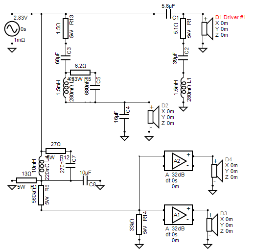
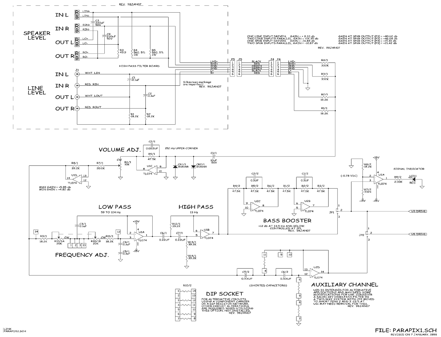
Plate amps convert speaker level inputs to line level signals without high wattage load resistors. My speaker testing jig also drops the amp output to run into my sound card without a high wattage load resistor. Plate amp schematic
Interesting. 560kΩ 1w resistors. Then I suppose the 332kΩ are impedance matching?
Could do something similar, tap straight off the fullrange speaker level signal and use a passive line level lowpass instead? Would save alot of heat and component cost.
1 Like
This is true. But @Eggguy is not using a standard plate amp with built in analog active LP filter. He is using an off the shelf class d amp to run the woofer. The woofer LP filter is being done passively, just like a normal passive 3 way speaker. That is why a high wattage 10 ohm resistor is needed. This big resistor is functioning as a virtual woofer voice coil so that the passive LP filter network is loaded down properly.
We still need to convert speaker level inputs to line level signals, the same as a plate amplifier does in your example. This would need to be accomplished by another set of low wattage resistors at the input of the class d amplifier. In your example, they used 560k and 330k resistors to form an L pad to drop the speaker level signal down to a line level signal. They are also using a pair of clamping diodes at the input to prevent overloading the inputs of the TL-074 op amp. And a 10uF 50V series cap to strip off any potential DC at the TL-074 inputs.
Reminds me of the ARTA/LIMP box.
1 Like
Can someone share a sketch of this proposed setup?
Ron
I’ll rough up a block diagram tomorrow. I think I have a fairly good idea of what @Eggguy is planning.
Z in of my amps. is 33K Ohms. This is just a brain fart of mine. I will not be offended by constructive criticism, or any comments for that mater. I have daughters
I do not have the driver files loaded yet.
The 13 ohm resistor may get hot.