Does the messing up of the impedance and phase by breaking the speaker in two to bi-amp cause problems? Example:
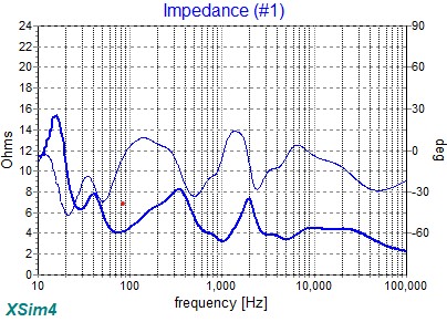
System as a whole (impedance and phase is reasonable across the board):
Does the messing up of the impedance and phase by breaking the speaker in two to bi-amp cause problems? Example:
System as a whole (impedance and phase is reasonable across the board):
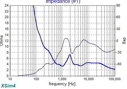
And here is the HP:
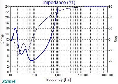
On the low-pass the phase starts becoming sketchy at 200hz. Impedance is rising steeply, does that make it a non-issue or is it a problem?
On the high-pass the phase is already at 45 at 500hz, and the crossover point is 100hz, meaning it gets to 60 and beyond before the crossover point..
Should impedance compensation networks be implemented if bi-amping?
Remember -45° is the most negative phase can be.
Not sure I’m tracking Ben; can you clarify?
I was never good enough at math to get a physics course, so please forgive my ignorance.
I remember hearing 45deg is the most challenging phase angle because it is the farthest off both voltage and current. Is that correct?
Perhaps I just answered what I was asking for clarification on - so is 60 the same as 30?
I should rephrase, the most capacitive phase can be is -45°, because phase is plotted on a tube. +45° is the most inductive.
Fold the phase plot rearward where the +/-180° lines touch.
This could help you decide whether or not to do something.
Sorry. Phase is the hardest thing about this hobby for me to understand, whether acoustic or electrical.
So are you saying that when it’s more negative than -45 it’s actually becoming inductive and vice versa, or at least still capacitive but heading back toward zero - indicating that -60 is really no worse than / the same as -30?
I might not end up understanding.. I guess maybe I might just need an is this an issue yes or no answer lol.. But as long as people are patient enough to keep explaining I will keep trying to make sense of it.
From what I make of it the phase is representative of the filter impedance, which will infinitely increase without another filter. But on the high pass it is almost -90deg at 100hz, roughly the crossover point if the system was one.
I don’t mean to question but if plotted on a tube, which actually makes sense to me, wouldn’t -90 be the most capacitive it could be?
Sounds like you understand how I explained it. -30 = -60, in terms of capacitance.
The phase is plotted as the “rate of change” (derivative, from calculus) of the curve it is related to, no matter impedance or FR plot, and is a 3d plot on a tube. The plot can’t be referenced to 2d and viewed with clarity unless it is unwrapped like we typically see.
Ok, so then if this is the case, then -90 is not a purely capacitive load (seems an amp may not appreciate that) and there is no need to worry about the phase reaching +/- 90 as it tapers off with the filter. I.e. the bi-amp load is no harder or more dangerous to the amp than the assembled system staying mostly inside +/- 30, +/- 45 max, correct?
As long as the impedance does not dip low at the same point of being -45°, it should be okay. The impedance compensation of a high Z peak to flatten it out will reduce the rate of change, and therefore have both a flatter Z and phase. This is about having a benign load to your amp.
The FR (or acoustic) phase is more often than not preferable to be between +/-30°.
Sounds good, thanks much Ben. Not gonna worry about it and send it.
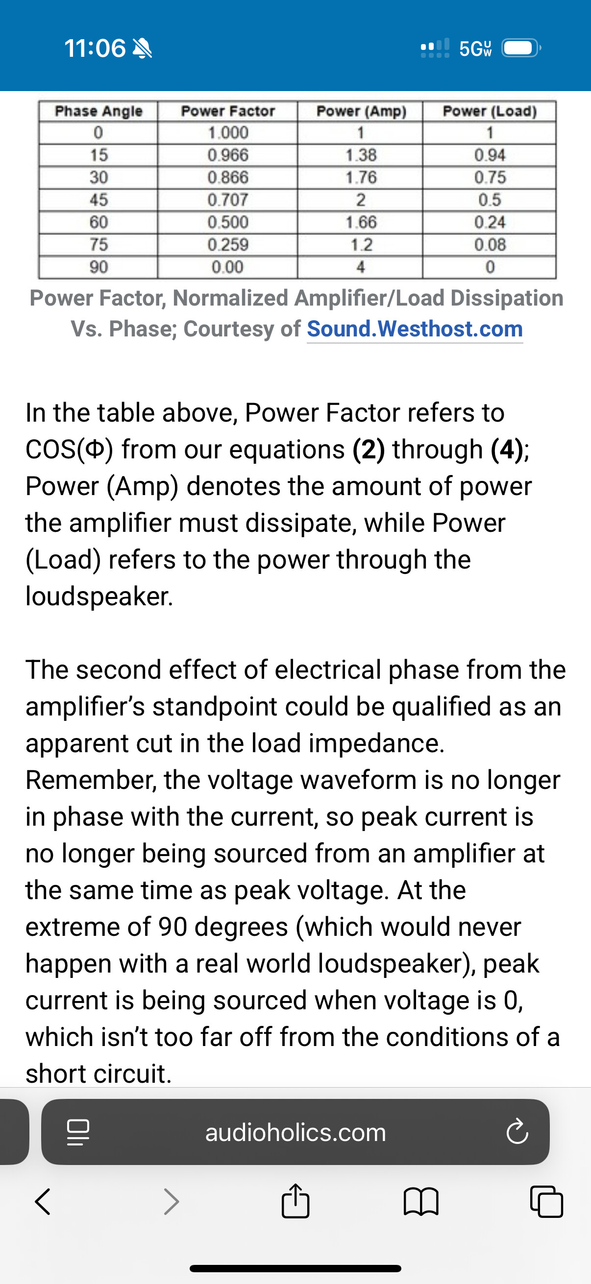
Not meaning to question, Just trying to learn more about this and came across this. This indicates phase does go to 90, which makes sense as a quarter of the cycle, and indicates 90 deg is virtually a short circuit to the amp.
Both the hp and lp if separated reach 90 deg within the audio band. I know The impedance is super high at that point. Is it that even though any output in that range is nearly 100% current based, the output is so low due to high impedance that the current is not enough to be concerned with?
Could you post the woofer crossover? It looks highly inductive, like an inductor and nothing else.
Definitely is highly inductive, hammering an 8 ohm woofer to a 100ish hz (closer to 125-150) crossover point passively.
Third order electrical: 4mh, 500uf + 4ohms, 9mh
Comes together fine as a system. Really just wondering about the phase when broken apart to bi-amp.
It may be normal for a hp or lp filter by itself to inevitably hit 90deg as the impedance rises toward infinity? I think that is mainly what I’m after for an answer I guess. Thanks
From what I am seeing online it looks like it is normal and just what happens for phase to go to 90 deg on a hp or lp filter without another filter the other way; as the impedance heads toward infinity so does the phase. Perhaps I have just never paid attention to it before and am over thinking it..