Almost 7 years ago, @KenRhodes gave me an old burnt out looking tube amplifier that needed alot of work to bring it back to life. But every time I put it on my bench to take a look at it, I always seemed to end up taking it off my bench after a few hours and putting it away again because I needed to find or order new parts or I needed to work on something else. But now I finally have all the important parts that I need, so no more excuses or procrastination!
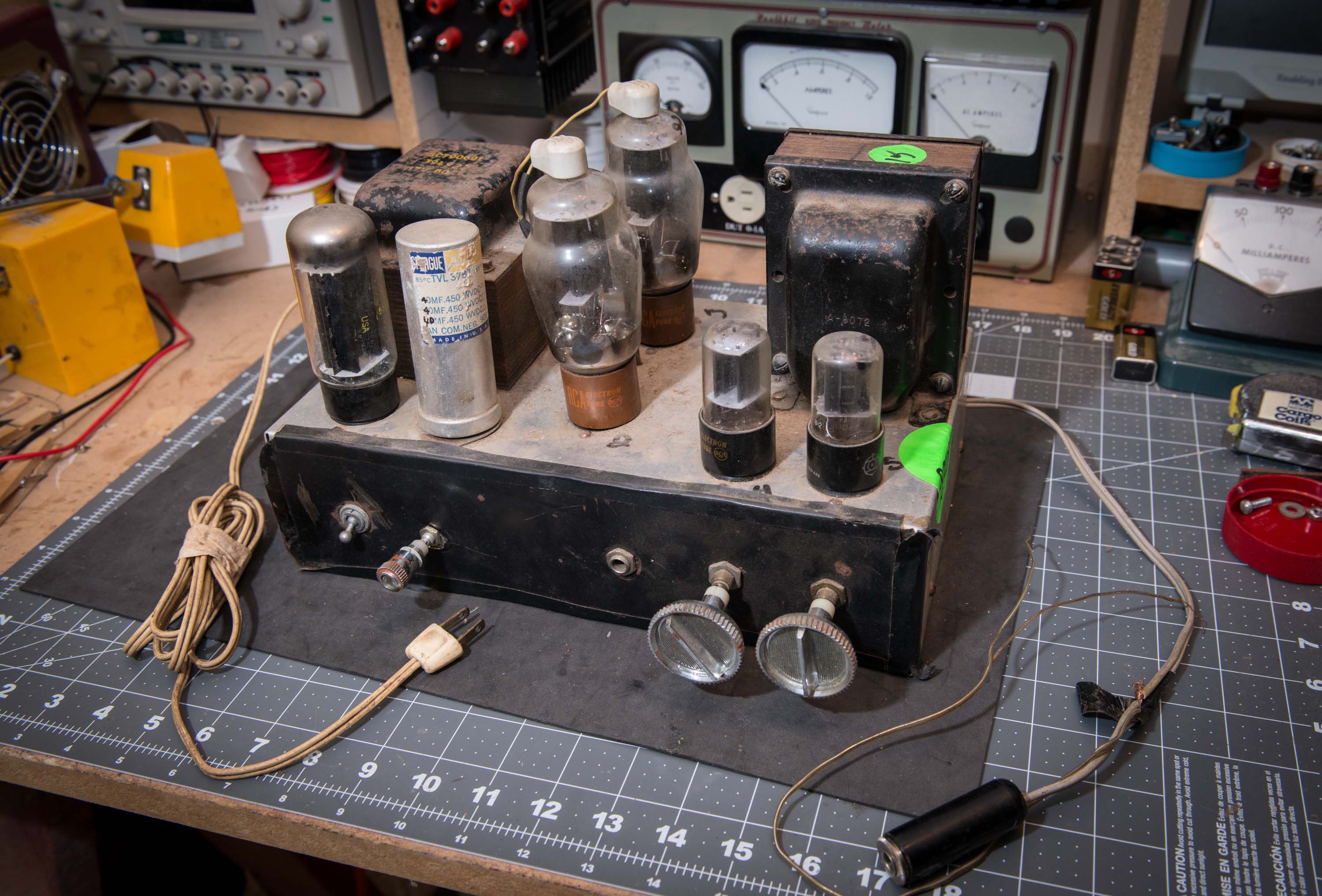
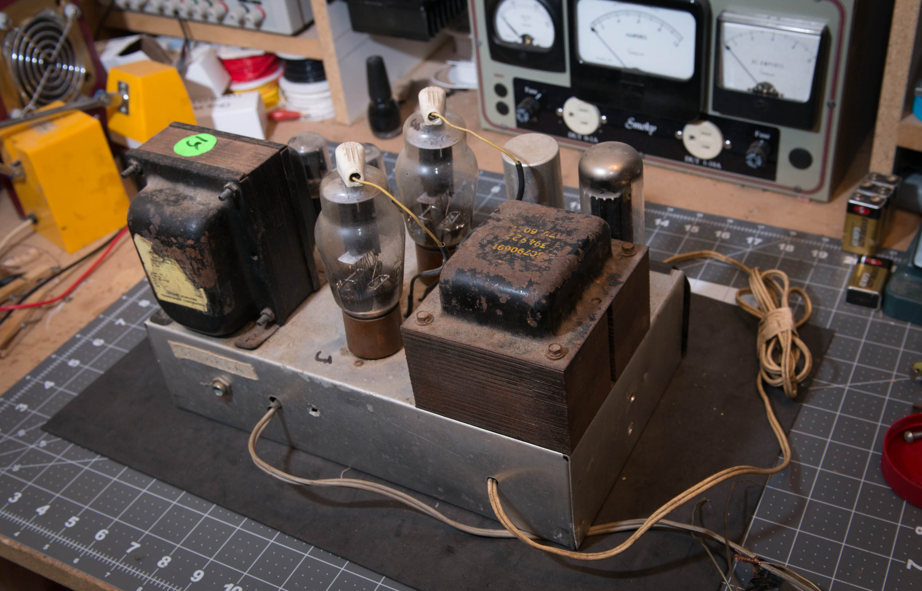
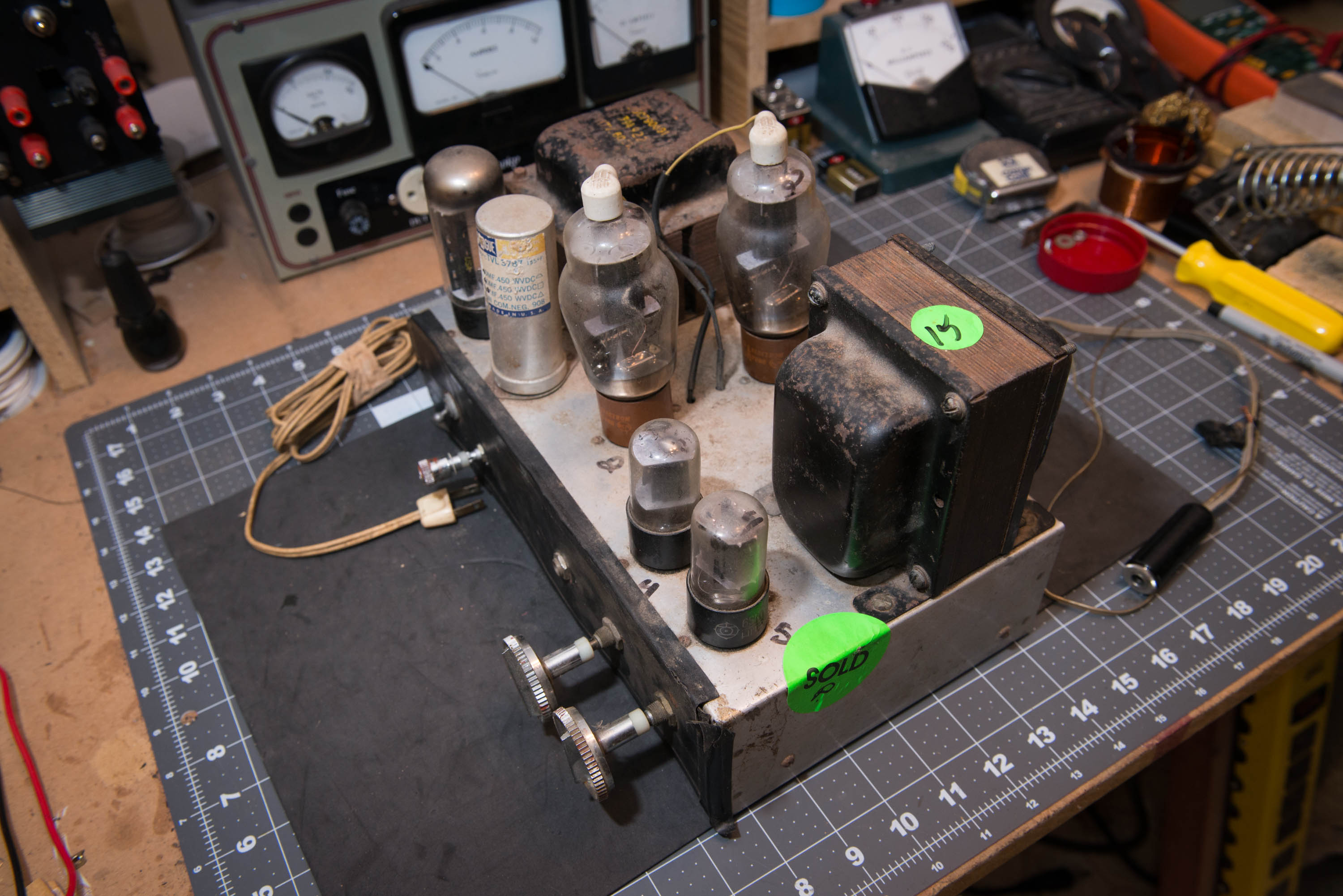
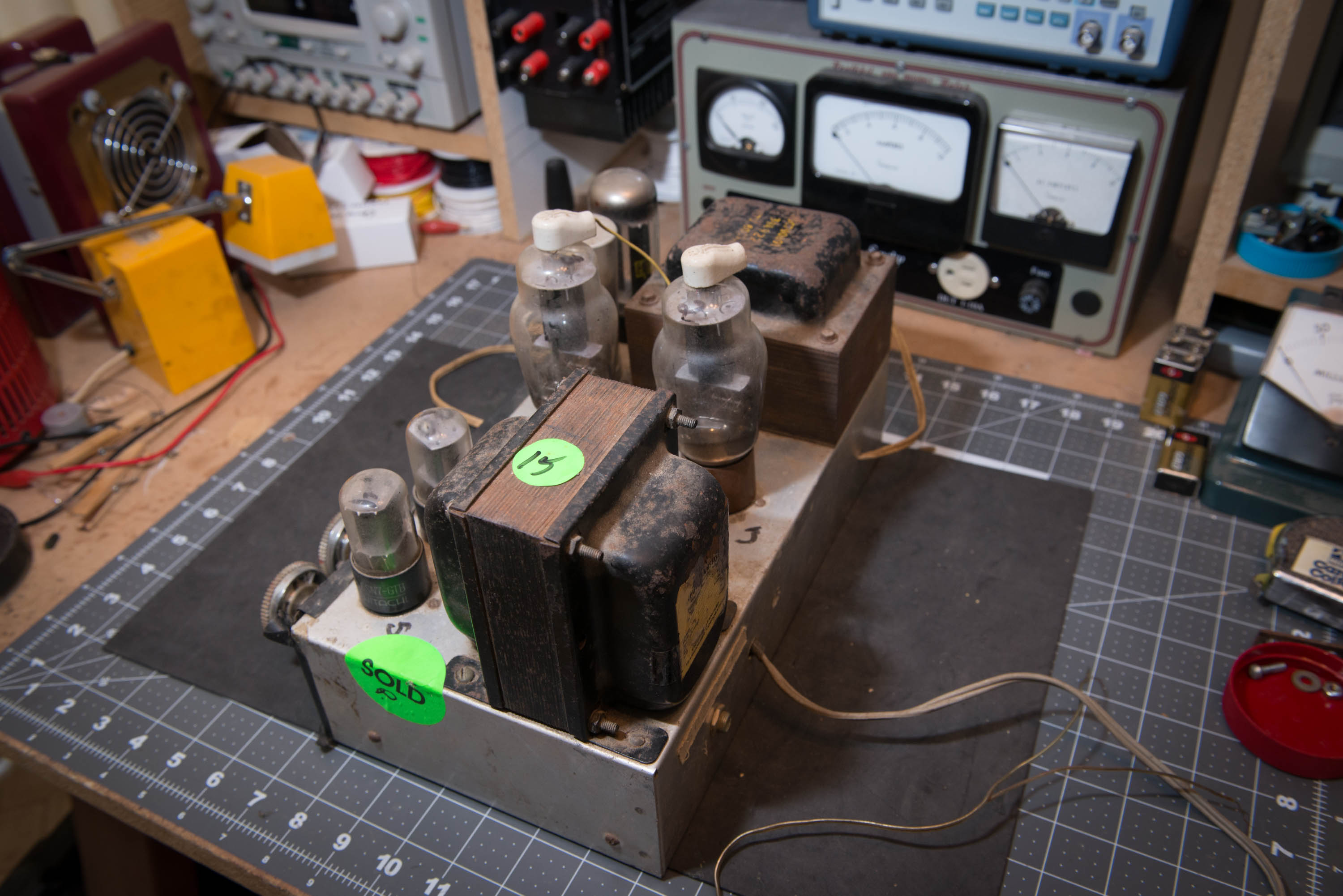
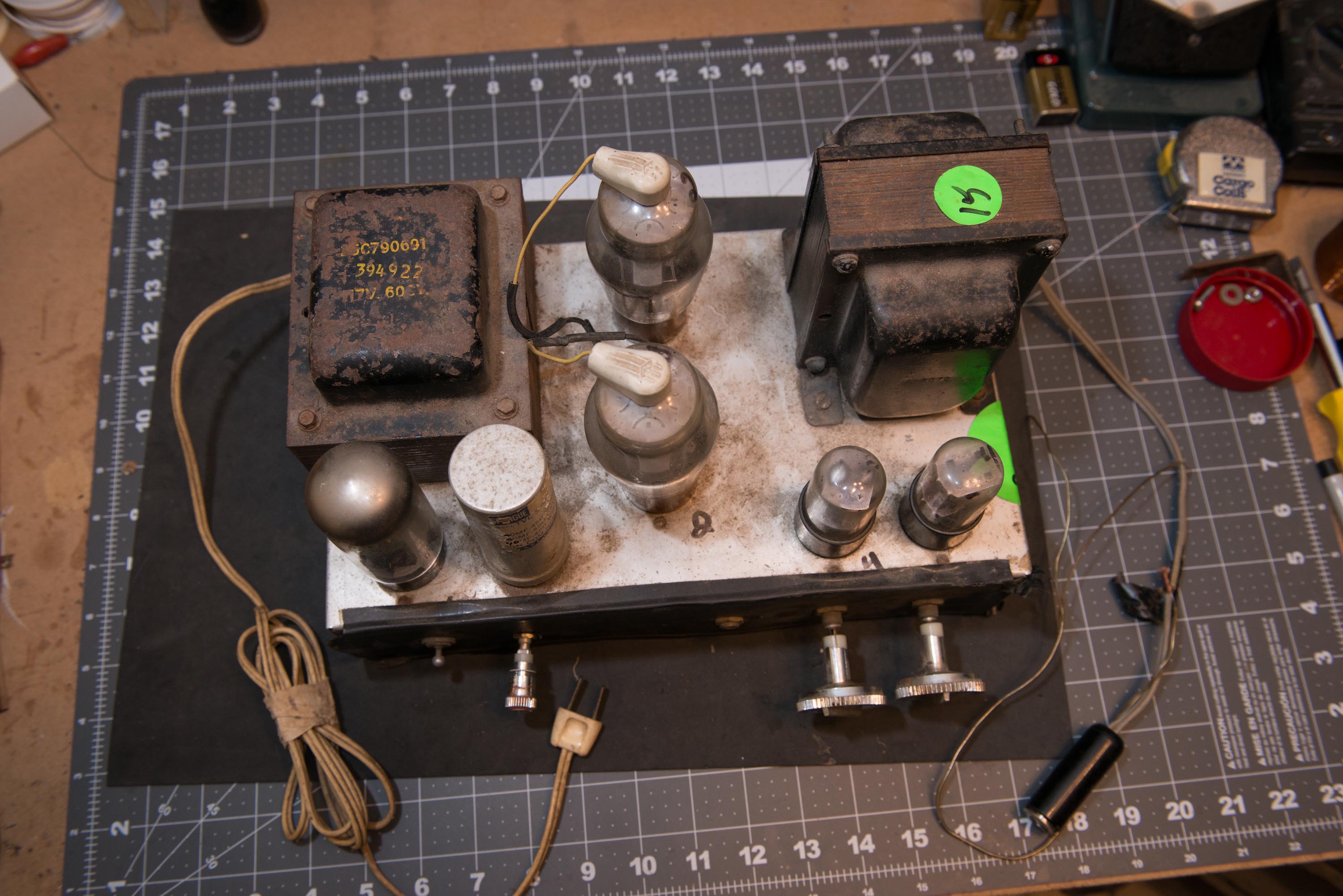
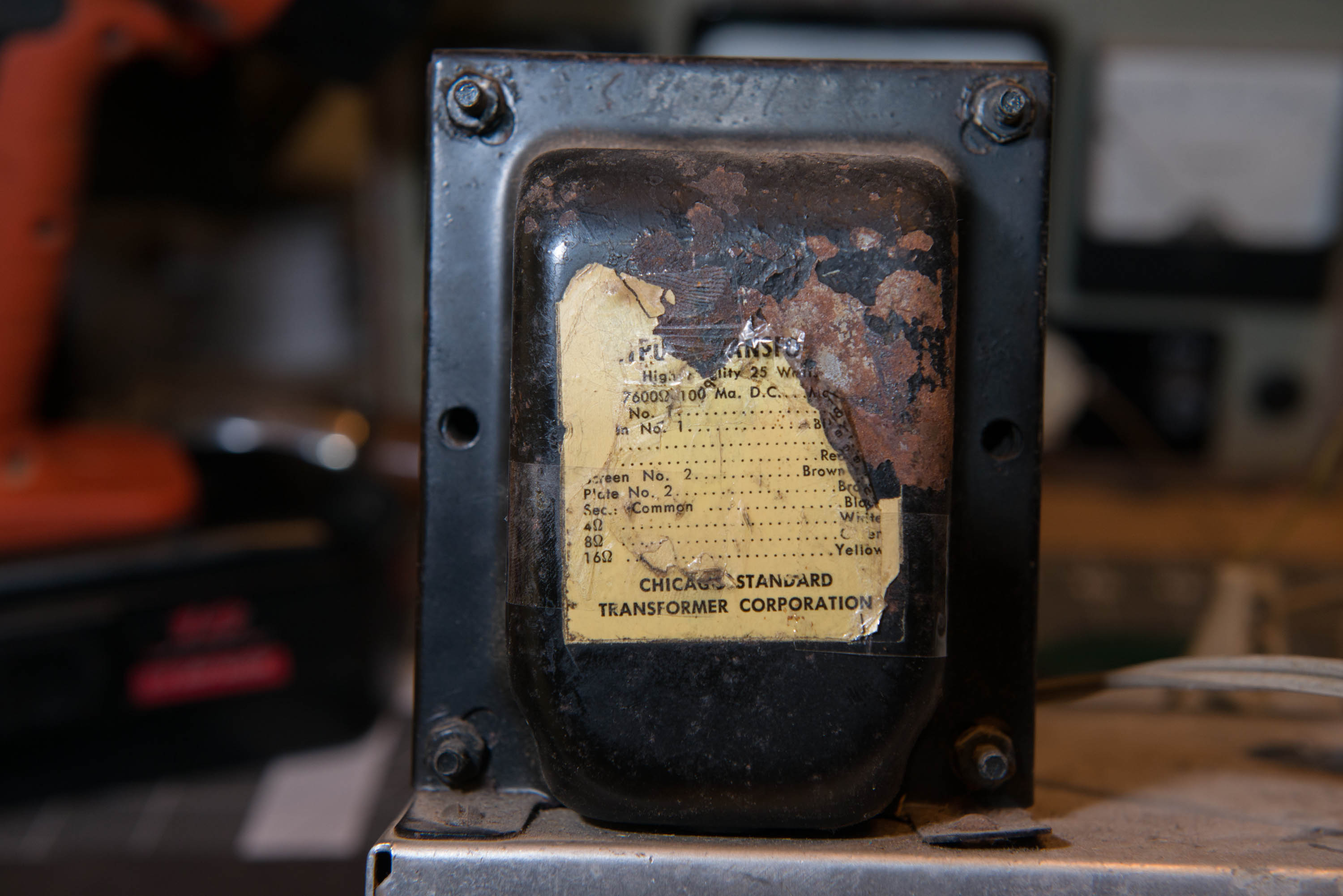
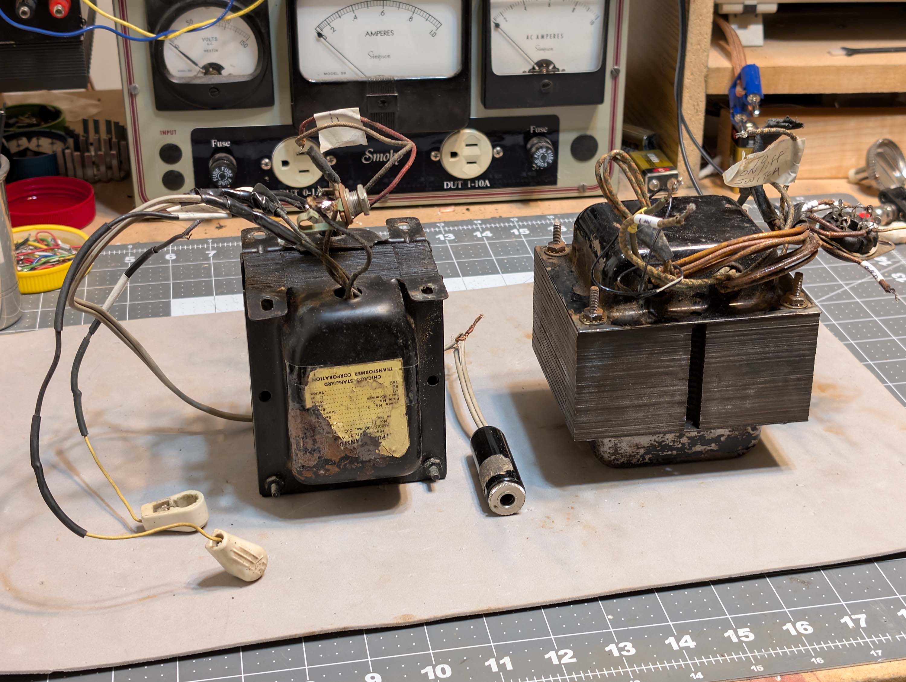
This amp is a 1950’s “home brew” Williamson from the late 1940’s to early 1950’s pre-stereo “High Fidelity” era. I traced out the circuit and discovered that it is very close to the original Williamson WA-1 amplifier that Heathkit sold as a kit back in the 1950’s. It uses a 5U4GB rectifier tube, two 6SN7 tubes for voltage amp/phase splitting, two 807 power output tubes in push pull, and a big, hefty power transformer. The output transformer is a Stancor A-8072 (Chicago Standard Transformer Corp) rated for 25 watts. This was alot of power back in the 1950’s.
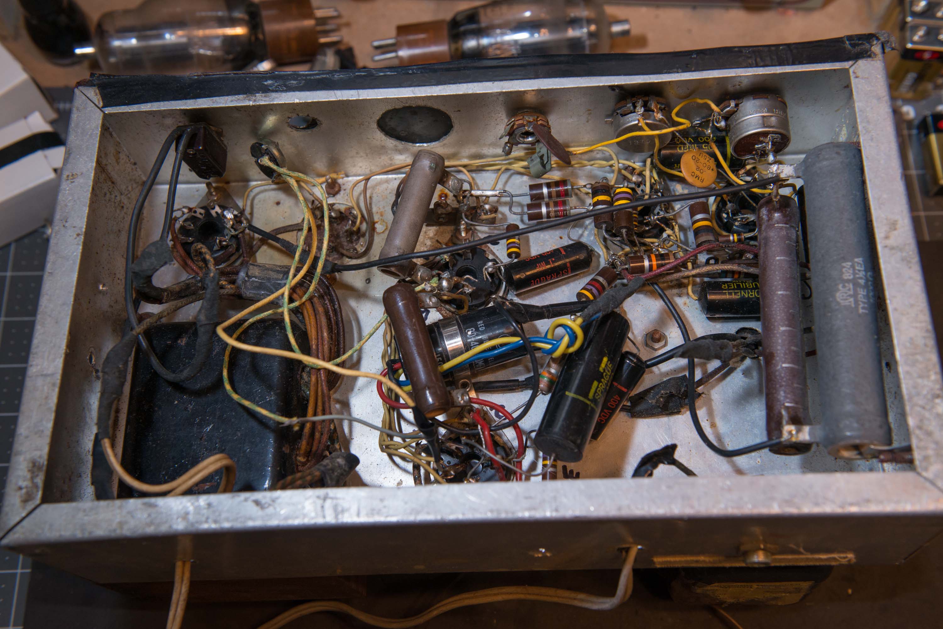
Currently, the amp is completely disassembled on my bench. I’ll stop back with a few update and finished pics as the project goes along. Plan is a complete re-build. New tube sockets, caps, resistors, wiring, pots, and tubes. Everything except the power transformer, output transformer, and chassis will be replaced. My overall plan is to gather all the parts for a complete classic 1950’s style monophonic “High Fidelity” system and this will be the power amp to drive a big, 1950’s era, horn speaker system.
I agree! Neat project. Too bad you don’t have two of them. I’m sure you will tidy up that point to point mess a bunch and make it safer (I don’t see grommets where high voltage wires pass through the metal chassis.
I’ve never heard of any degradation, but it may be possible. Some of the old ones I have use what seems like a reinforced coated fabric material and some do seem like paper.
Off topic but kind of on topic. I was using dad’s stick welder, rather trying to do quite a bit of welding with it, but after a bit of time of continuous welding, it would start acting erratic, drop the arc, sputtering, sticking the rod, then back to normal. This is an old lincoln that grandpa bought new probably in the 60’s, if not earlier. Not much more to that welder than a huge transformer. We figure after sitting in the barn for so many years the windings/wrap in the tranx had finally drawn enough moisture to cause problems. That old amp surely wasn’t sitting for decades on a dirt floor in the barn, but it does make me wonder if the paper? between its windings might have deteriorated over time.
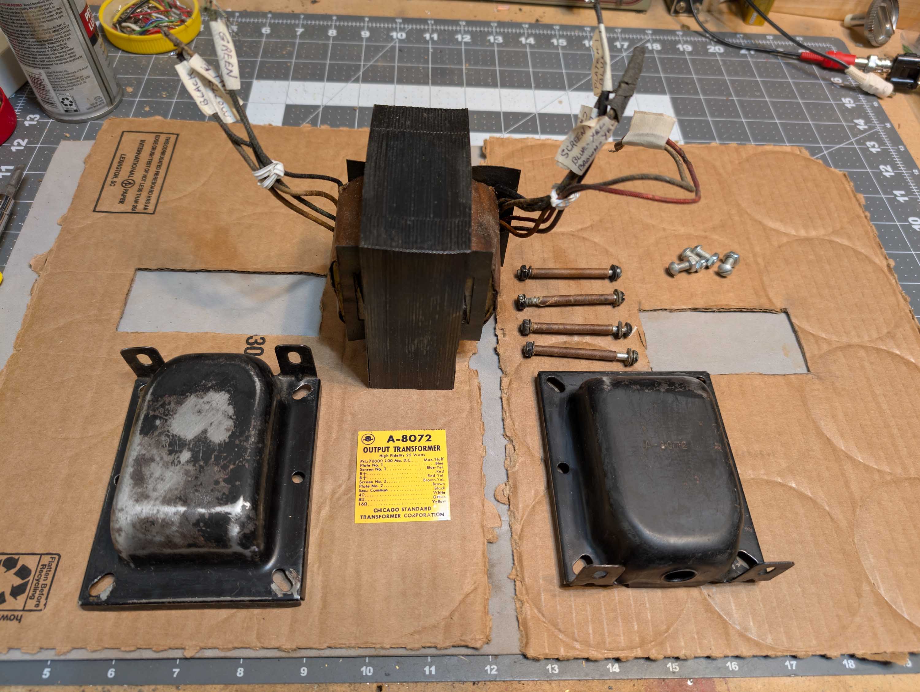
Output xformer:
Primary: 275 ohms total (129/CT/146 ohms)
Primary screen taps: These were taped off, so I didn’t measure them
Secondary 4 ohm tap to ground: 1.6 ohms
Secondary 8 ohm tap to ground: 2.6 ohms
Secondary 16 ohm tap to ground: 3.2 ohms
These static numbers look OK to me. I’ve also tested the main power transformer after ohming it out, using the 5U4GB and driving into a 55uF 650V cap and a 4.27K dummy load (simulating an approx 120ma load). Heater on the 5U4GB measured exactly 5.0VAC under load and the B+ measured 475VDC under load (555VDC with no load). Unloaded 6.3V secondary measured 6.58VAC. So far, so good. But time will tell.
Ya, that looks like a pretty good price for a NOS 807. I picked up two used 807’s at the Oak Creek Hamfest/Swapfest for $7 each from a guy that deals in large quantities of electronic surplus and tubes. Both measure very good on my Heathkit tube tester. So that gives me 3 good 807’s to work with on this project. Transconductance (GM) is 5400, 5100, and 4500 micromhos.
As a side note, one of the original 807’s (shown in the above photos) had a loose plate cap problem and the cap broke loose and fell off when I was working on it several years ago. The tube lights up but there is no GM at all. The wire sticking out the top of the tube was still long enough, so I tried to glue and solder the plate cap back on. But I could not get it to work again. I used a big 100W iron with lots of heat and liquid rosin flux. The flux boiled off intensely during the soldering operation. Maybe I cooked it too much. Some day I may try to re-solder it again just to see what happens. I have nothing to lose, as the tube is completely dead the way it is.
Thanks, Eric. I was thinking about doing something along these lines. Similar to what Craig is doing on his amp, but a little different. I could make the hardwood front panel wider so that it extends about an inch or so beyond the hardwood side panels. This would eliminate the need for miters. Miters would probably look better, but, just like Craig, I have also had problems getting good miter joints that fit tightly.
I could mount some new knobs, on/off switch, power cord, etc., directly to the aluminum box in the same positions that they are in now. Then create a cool looking “window frame” effect by cutting rectangular through holes in the hardwood for easy access to the knobs and switch.
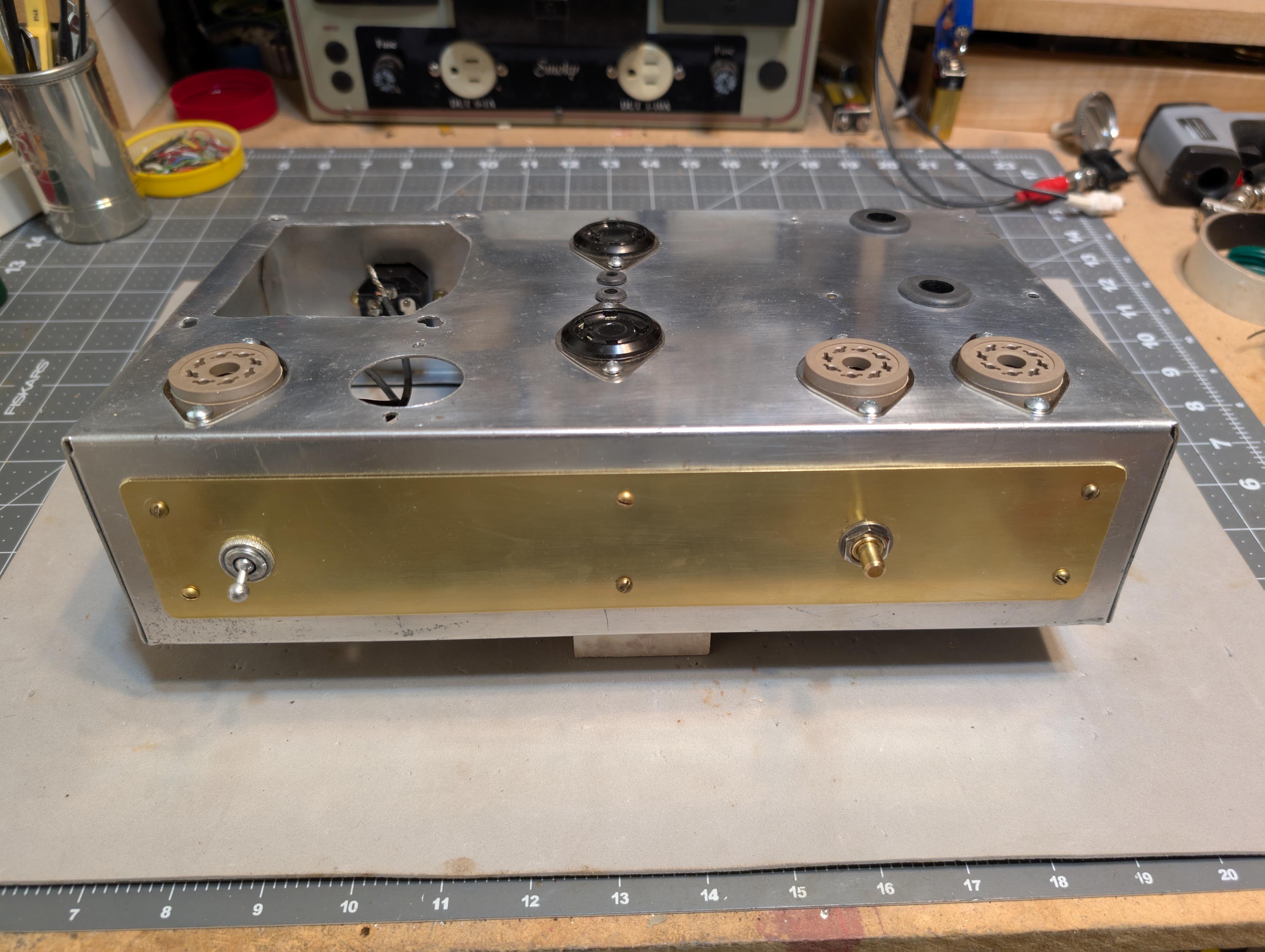
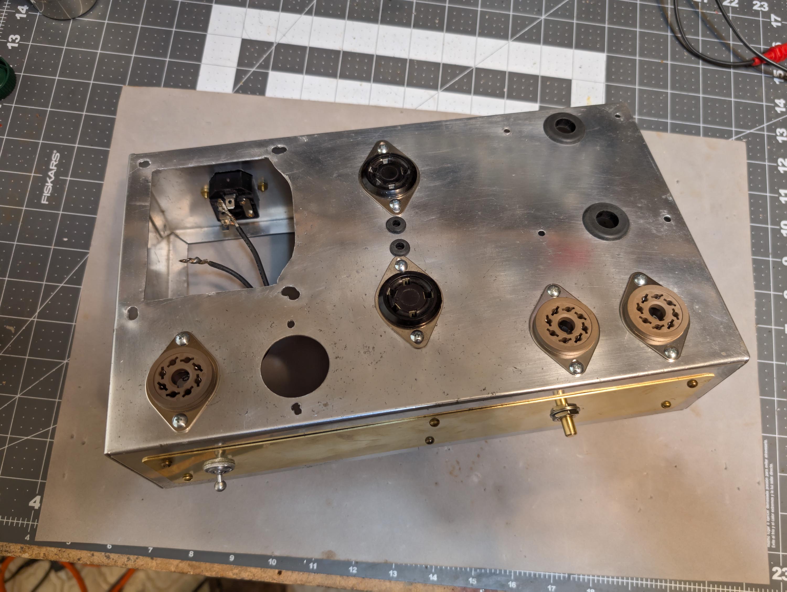
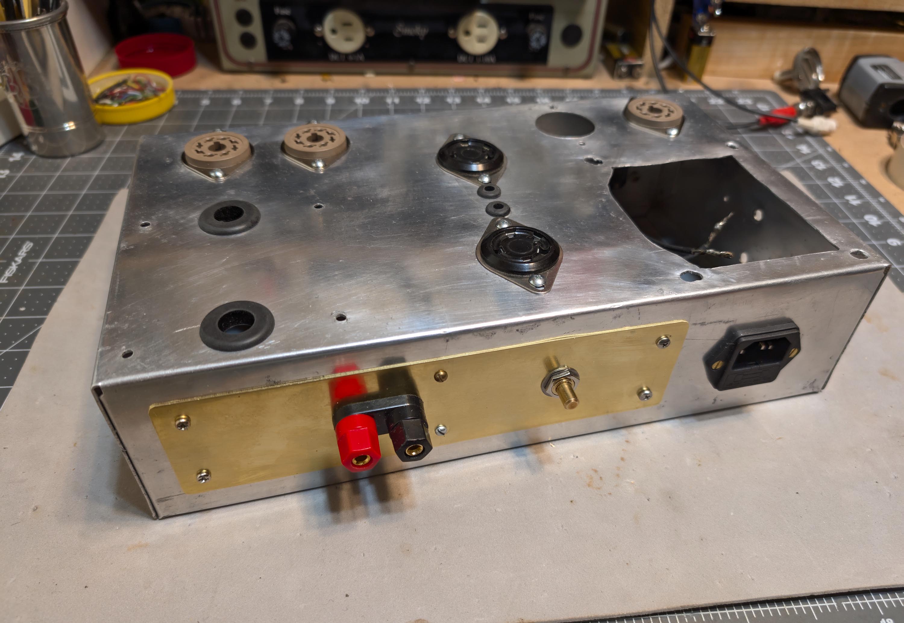
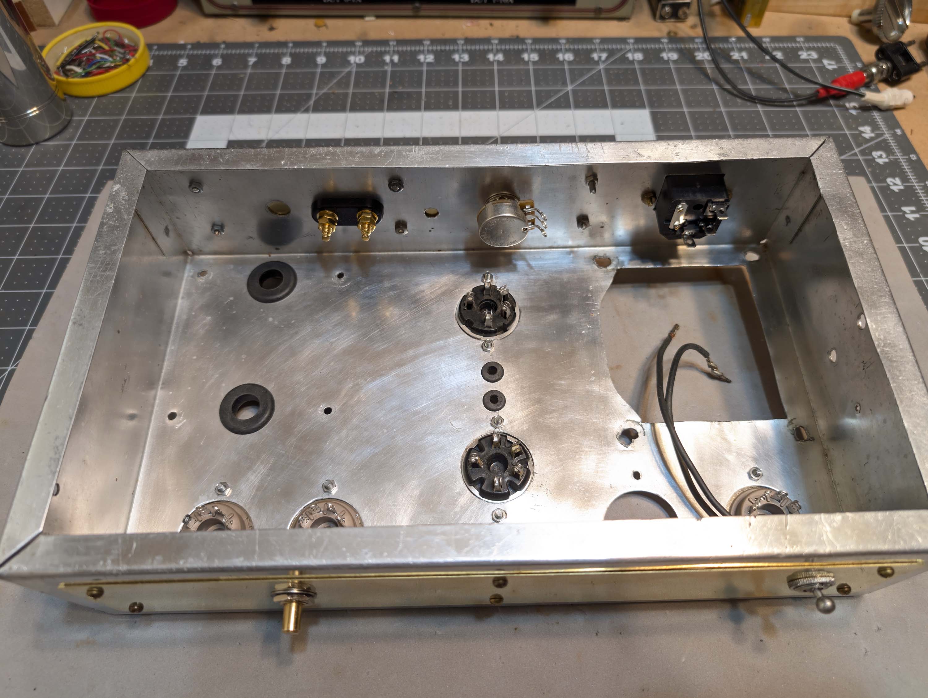
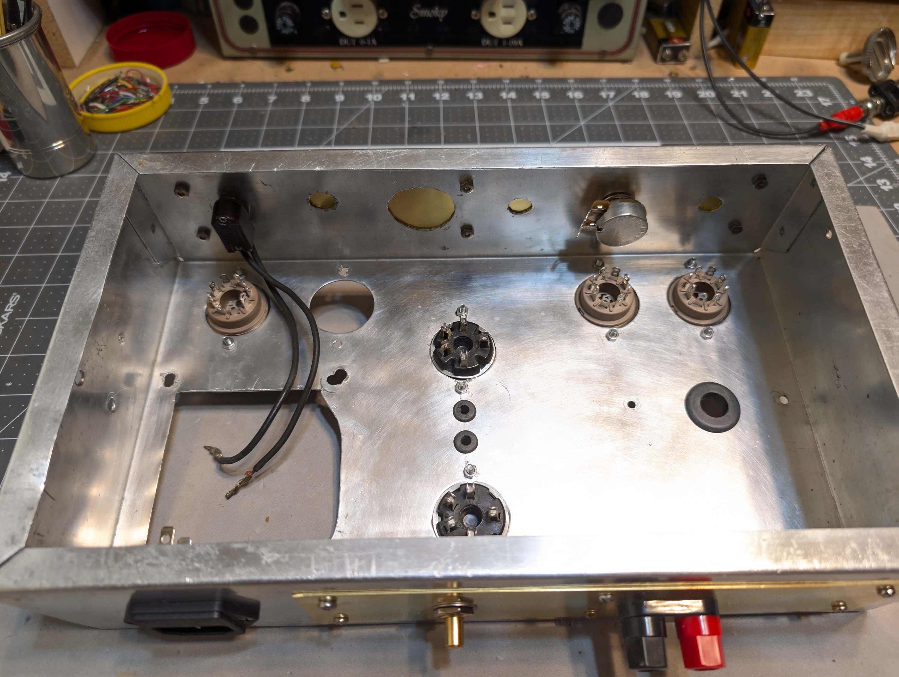
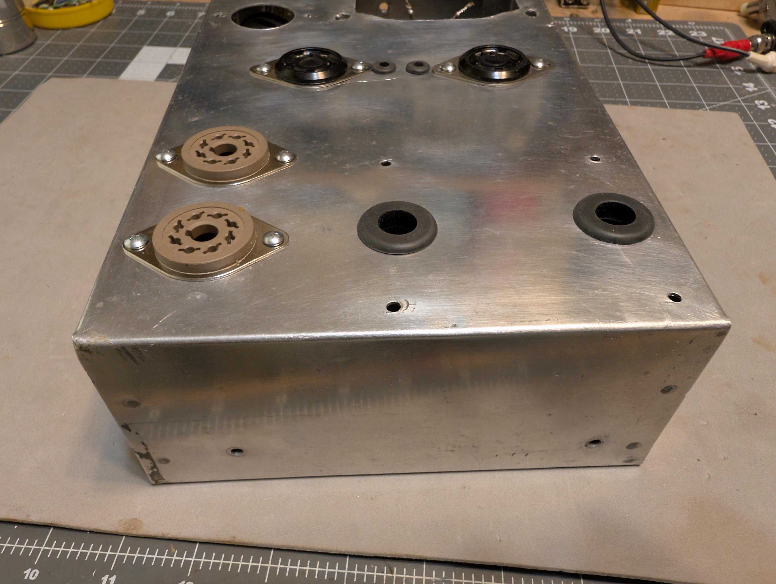
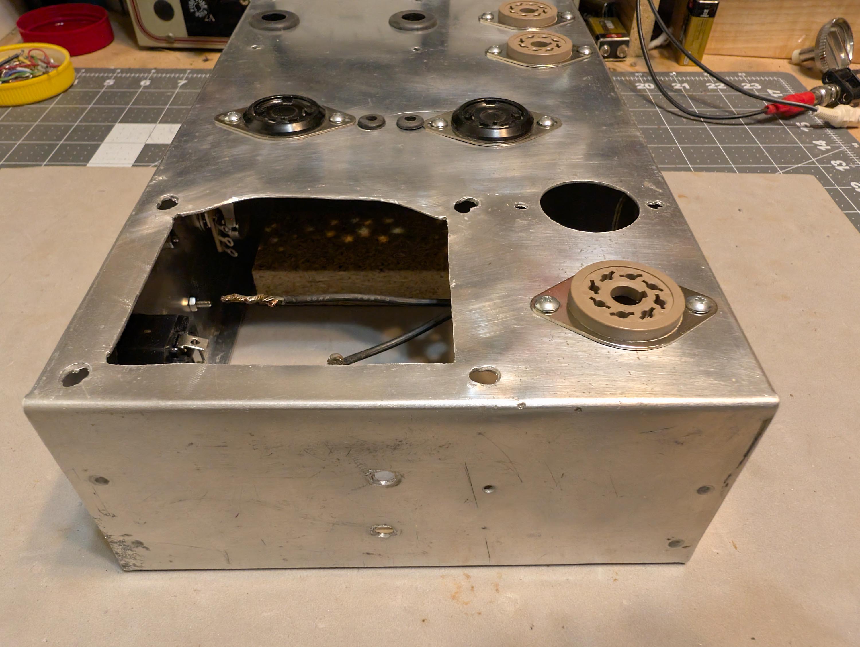
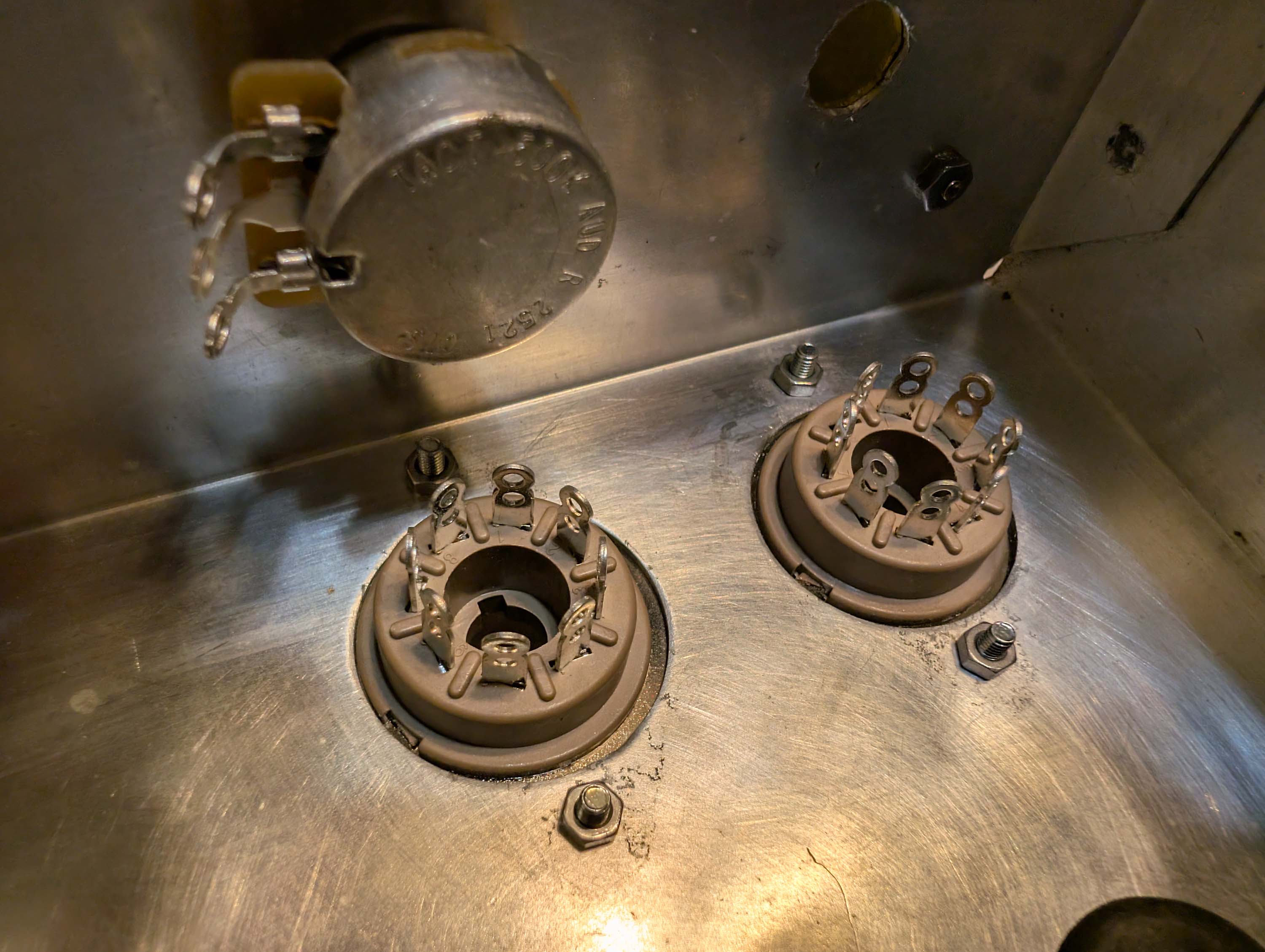
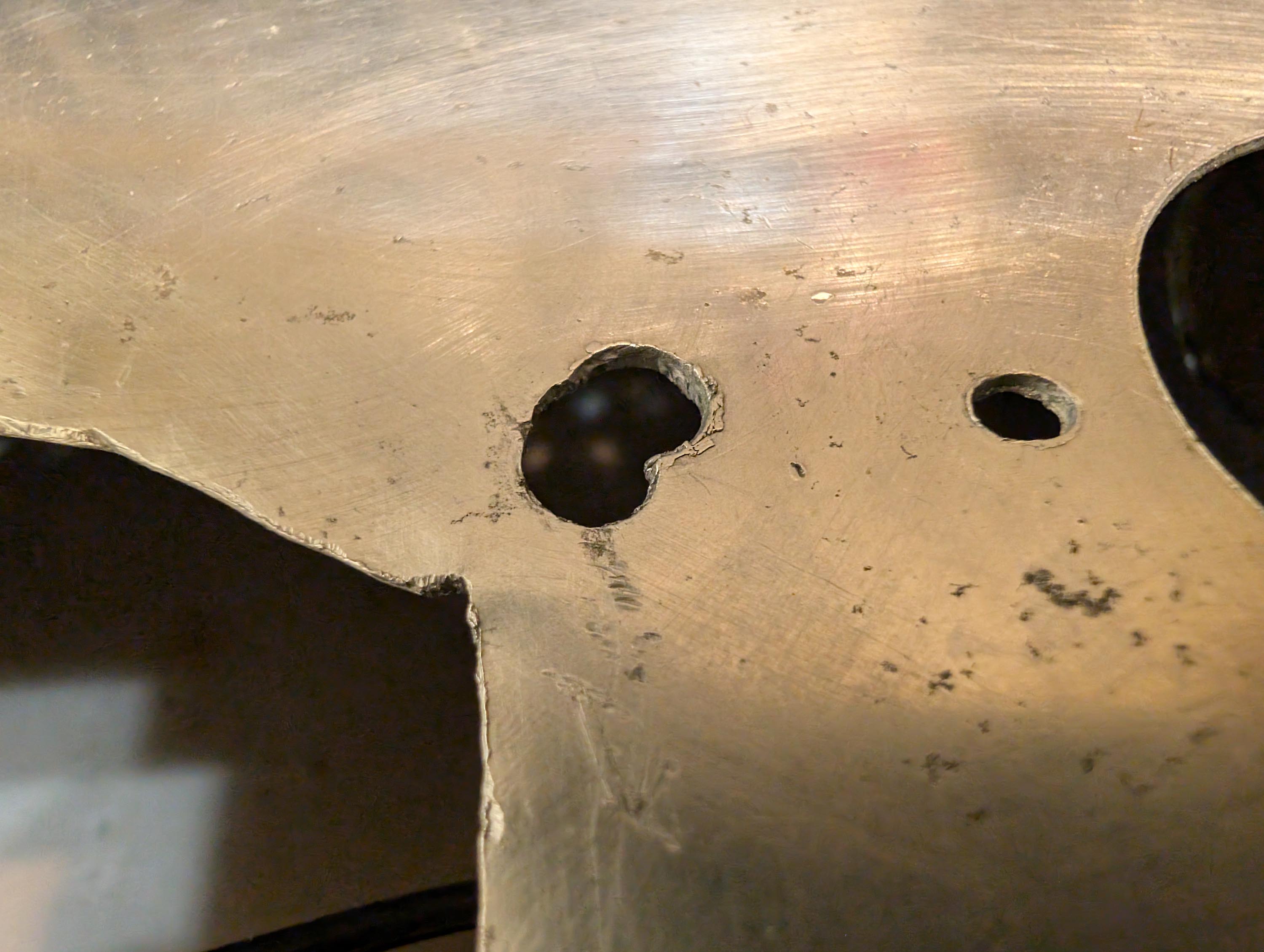
Made a little progress since my last post. I removed everything from the chassis and then cleaned and buffed it out. As you can see in the photos, many of the holes have been somewhat bodged over the years. But everything is still mechanically sound and once the transformers are cleaned up and re-installed, you will never see any of the bodged up mounting holes.
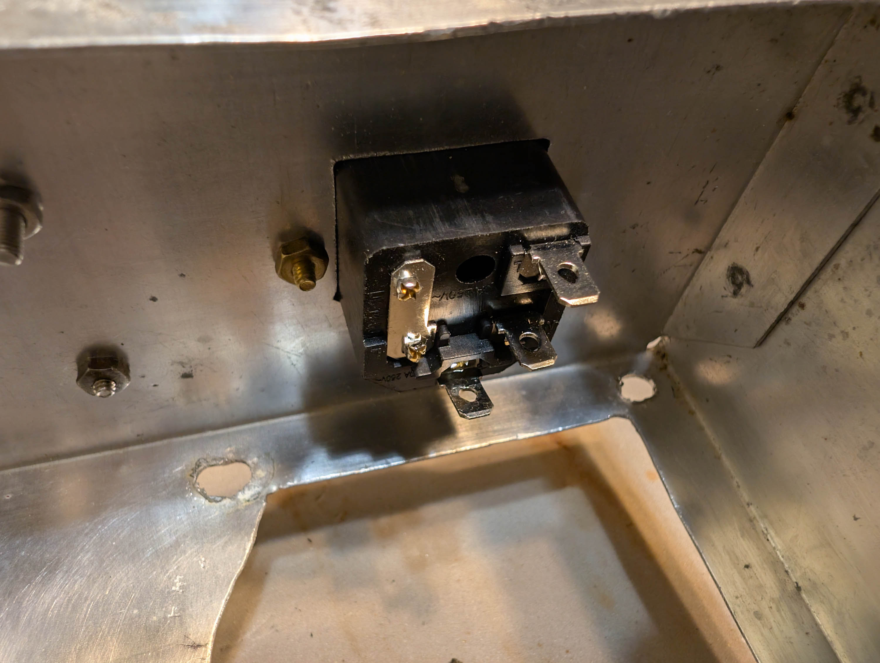
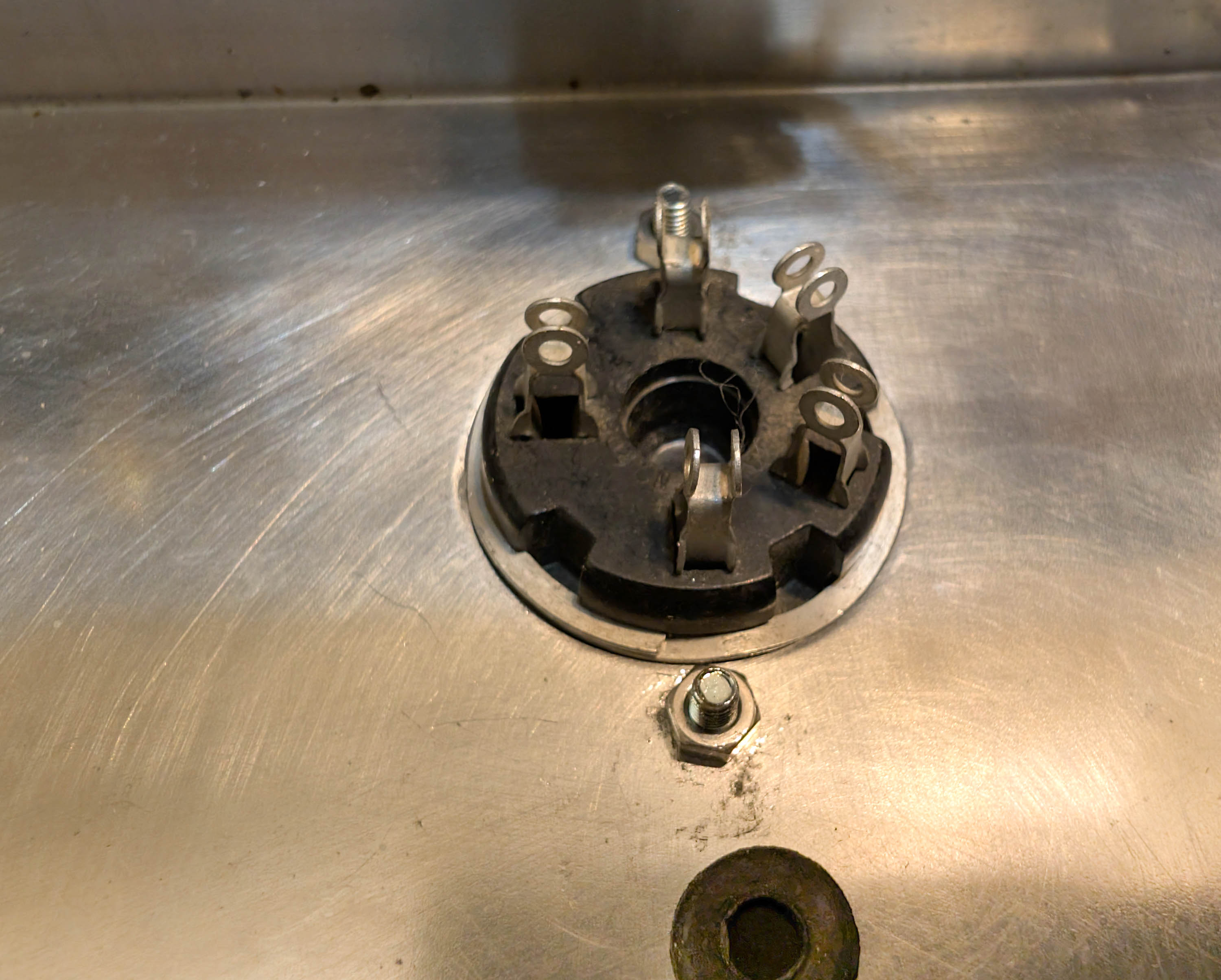
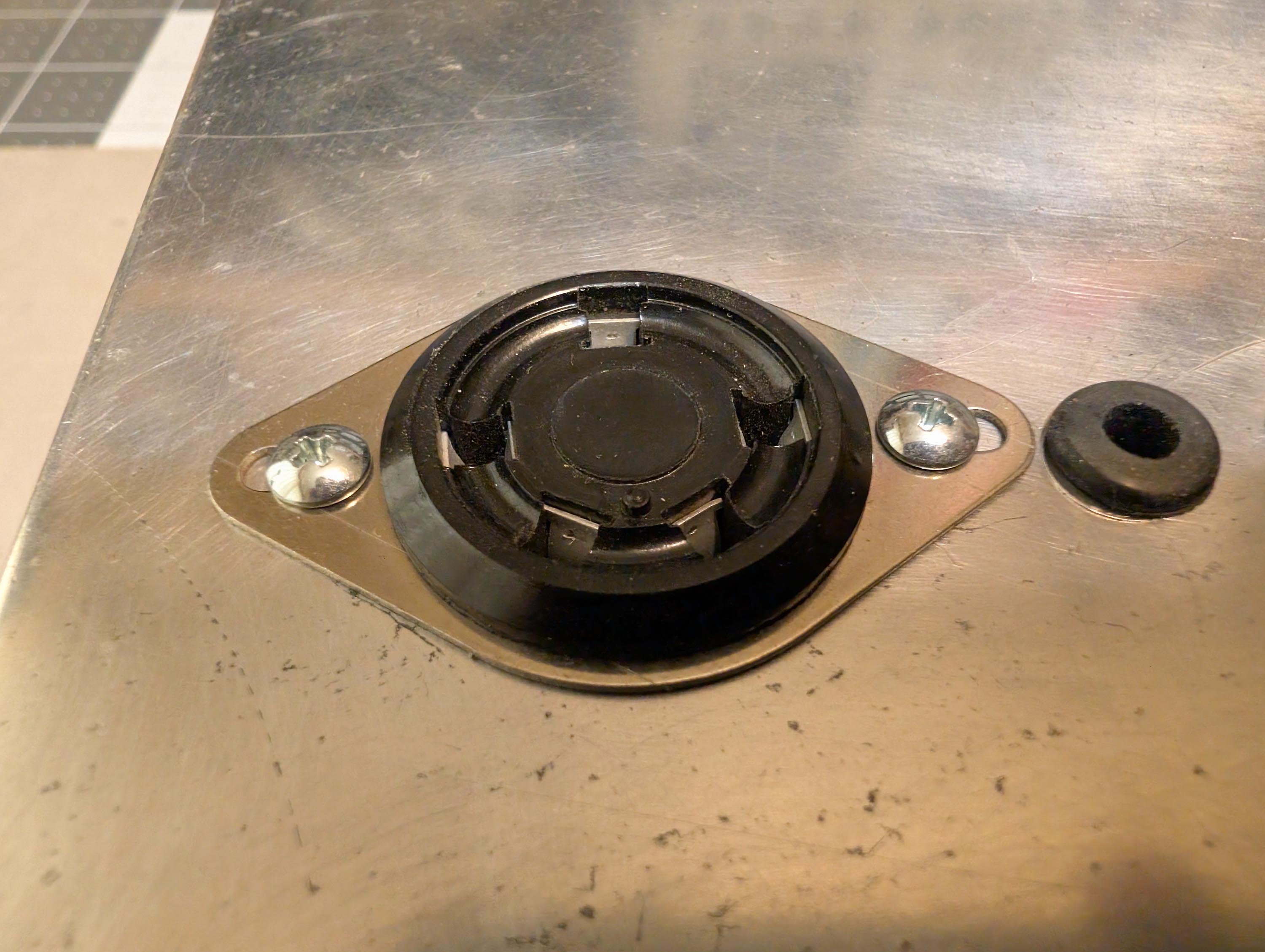
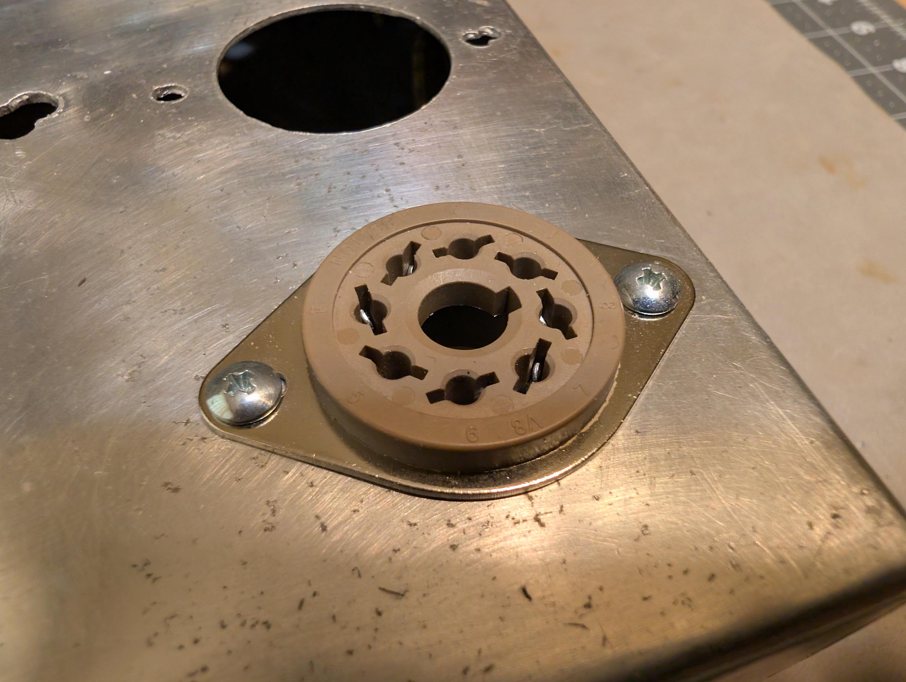
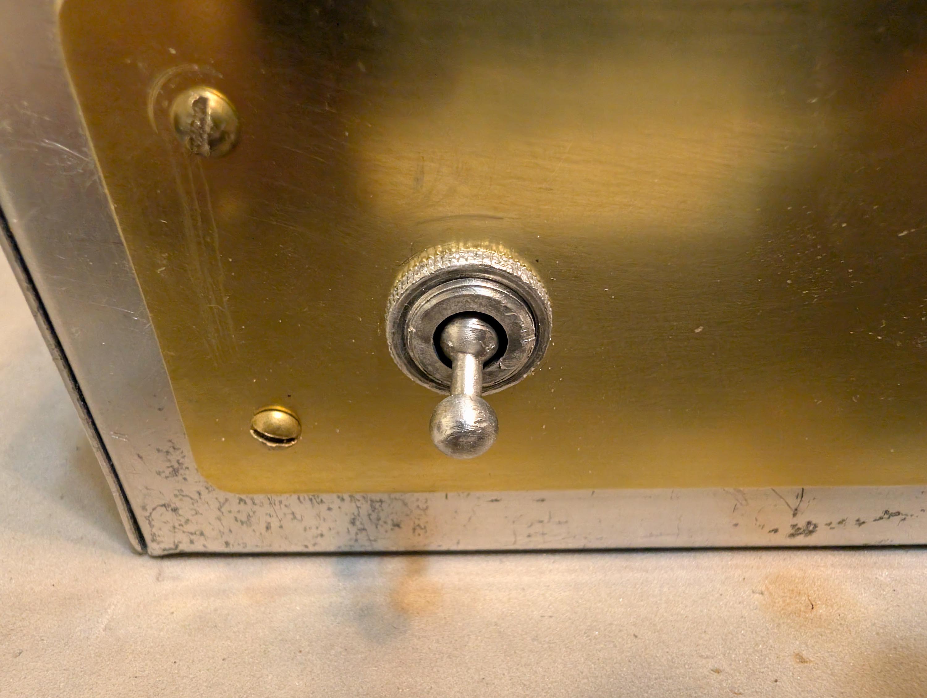
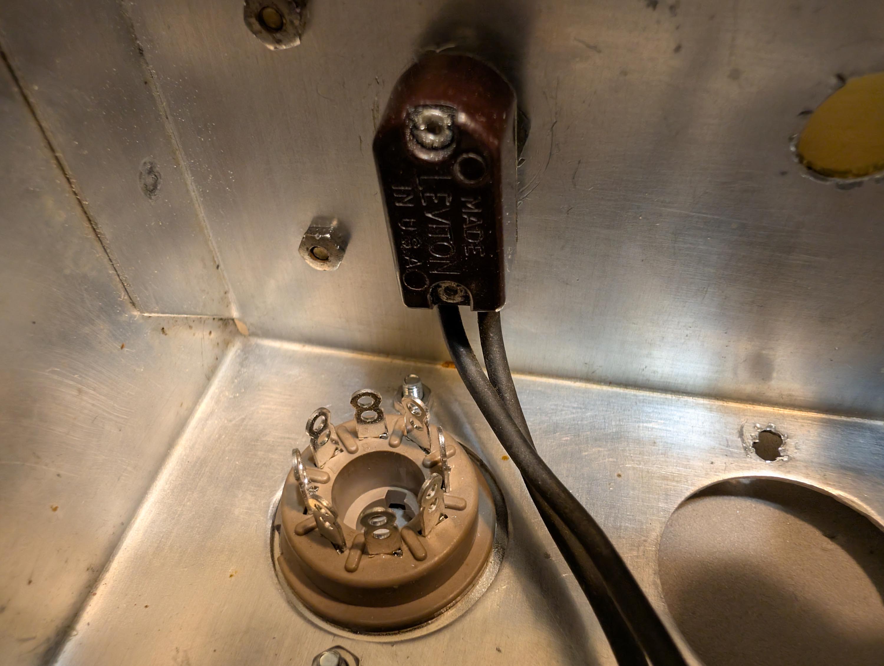
I widened the chassis wiring pass-through holes and added rubber grommets. I also cut a rectangular hole with my dremel and installed a new IEC power inlet with fuse. I covered the extra left-over holes in the front and back panels with 0.032 x 2" brass strip and then drilled it out for new pots and banana jacks. I then installed new and NOS tube sockets. The on/off switch was still good, so I re-used it. Don’t see switches like that anymore. Later on, I will add walnut side panels to dress it up a little bit and then make walnut picture frames to go around the brass strips.
Not the same, but there are still some ball knob toggle switches around at local stores. In case you make other items and want to keep a similar theme.
Or those old Leviton ones show up on ebay at times. Like this and this.
I can only remember the ball type switches being used on some older equipment. I’ll double check my local Menards, see if they have them in stock. This particular one (from the 1960’s?) seems to have a much easier and smoother switching action compared to several GB toggles that I recently bought at Menards. The GB units have a very stiff switching action. Maybe it just takes a while for the switching action to break-in and loosen up.
Been working on the power and output transformers, cleaning off the rust. I still have a ways to go before they are ready for painting. Looks like this coming Sunday and Monday will be very, very nice outside. Forecast is 63F on Sunday and 71F on Monday!!! Low humidity in the 40% range on both days. So I might be able to mask up the transformers AND my speaker bass bins and get a couple of coats of primer on them much sooner than I thought.
The output transformer is prepped and ready for the first coat of primer. As you can see in the pic, I cut rectangular slots in two pieces of cardboard to mask off the laminations during the spray painting process. My plan is to mask the laminations by press fitting the cardboard into position as I spray paint each side. Then quickly remove the cardboard before it sticks in place. Should work to keep paint just where I want it as I go along.
The original Stancor A-8072 wiring code label was destroyed during the cleaning and sanding process, so I made a new label in photoshop and printed it onto high gloss photo paper. I’ll stick this new label on with double-sided carpet tape after the priming/painting process is complete.