So I’ve mostly completed the new 3D model and have several parts printed. Before doing that I asked around on the Bambu forums to see what could be done about the warping I was getting on the corners of the larger parts. They were very helpful! I don’t know if any one of these changes did it, but the combination certainly helped significantly.
- Dry the filament for 24 hours. This was a step I normally do for just 6-12 hours for the nicer projects I do with PETG (usually not at all for PLA given how dry it is here in southern NV). I skipped this step entirely for the prototype prints, but this time I gave it the full 24 hours.
- Increase the bed temperature from the stock value of 70C. I chose 75C, no idea if it’s doing anything…but maybe?
- Turn DOWN the fans to keep heat in the chamber relatively high. I could also choose to control the temperature directly but that didn’t seem to be necessary - usually that’s only for the advanced filaments that need very high temps.
- Design fix #1 - Chamfer the entirety of the part that would otherwise make contact with the bed. I used a 2mm chamfer and made it a feature. This I had done before even asking at Bambu and it definitely helped a little. Someone here might have made this suggestion.
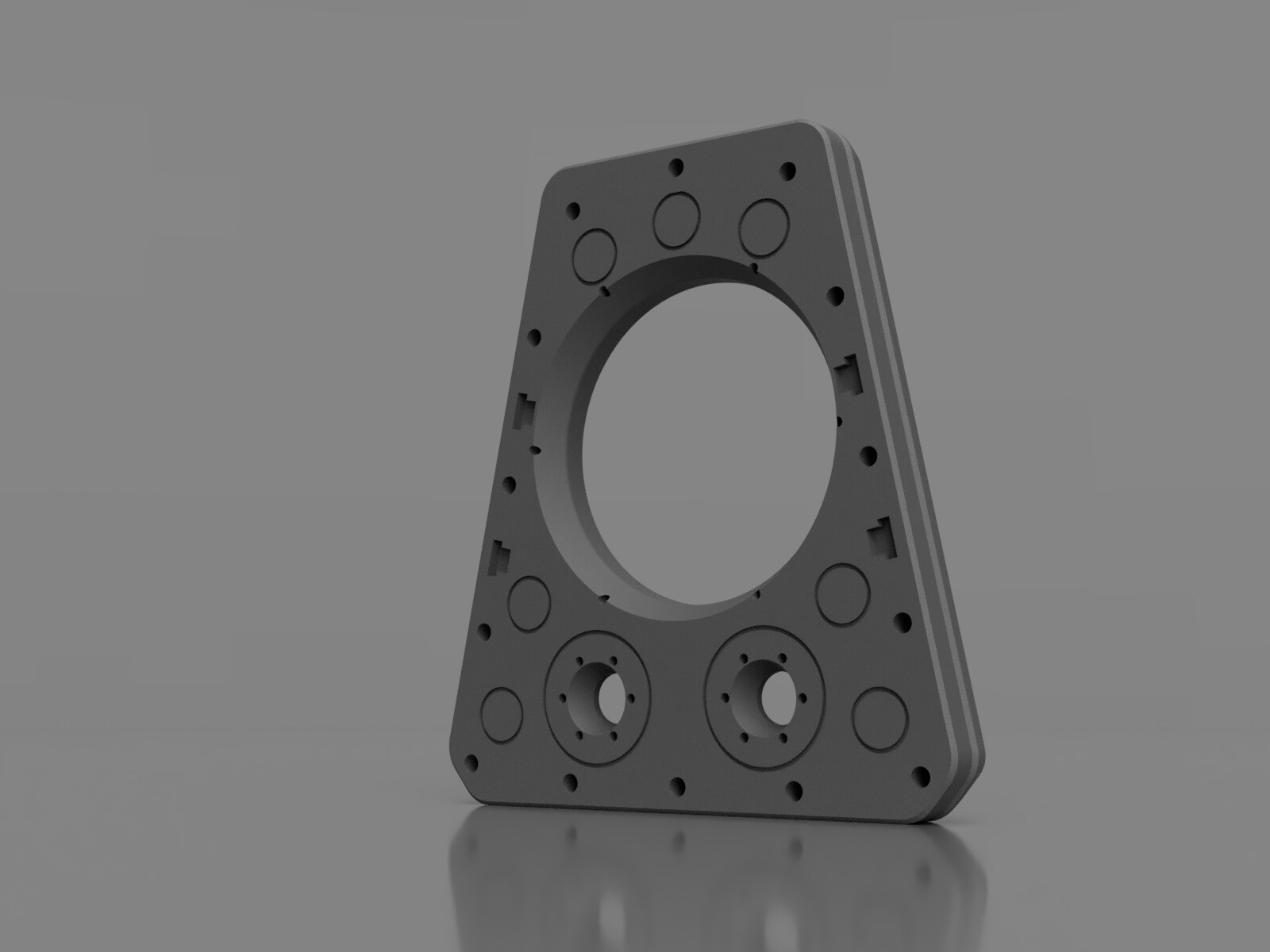
- Design fix #2 - Hard, sharp corners (as those seen on the bottom of the picture) are subject to the worst warping due to high stress on small points. The fix is to usually just round off the corners. I did this on the top, but for the bottom I chopped off the corner then rounded the remaining edges.
- Design fix #3 - Long, uninterrupted stretches that make contact with the bed are subject to the most stress. To alleviate this issue, you need to break up those stretches. I made some small, shallow circles on the backside of the part to do this. If the part were much more solid (i.e. greater than the 25% infill I used) It may be prudent to have the cylinder go nearly the whole way through the part and hide it with exterior skin on each side. This was unnecessary for my situation.
- Design fix #4 (NOT IMPLEMENTED) - One could also ‘ridge’ the edges of the design with tiny curves. I didn’t care for how that looked so I did not do this.
Here’s how the back of the rear baffle looks. I haven’t actually printed this part yet but the front baffle and mid chamber printed flawlessly and used the same techniques.
I also did a couple things differently on this build.
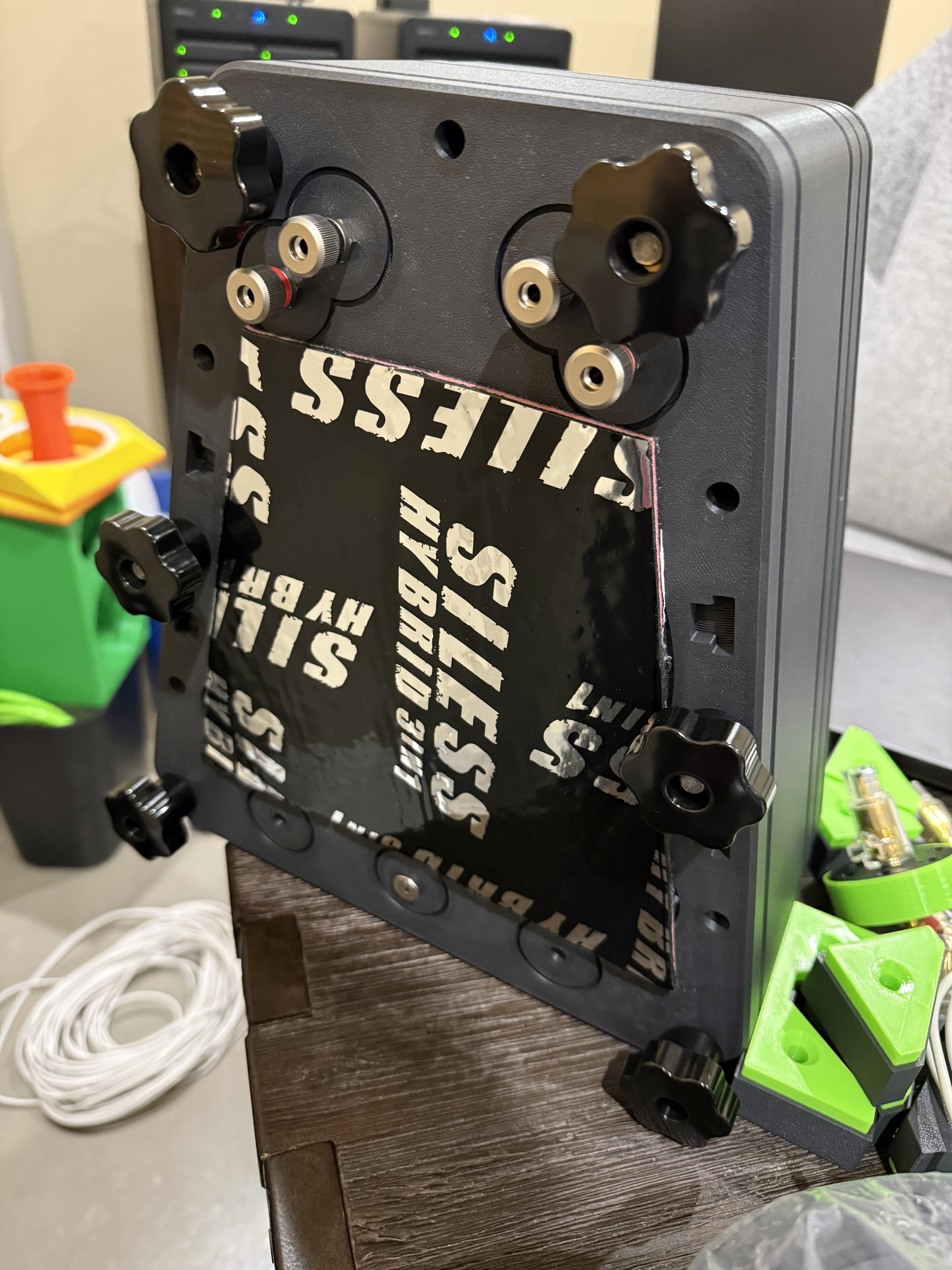
- Previously the bolt holes were inset by a least 12-16mm compared to how they are above, where they are relatively close to the outer edge. This was because they actually used bolts to hold everything together and you need to be able to access the bolt head. This time I’m using threaded rod that extends all the way through the speaker. I used M8 heat inserts on the back of the baffle (you can’t see them from the front), screwed M8 threaded rod into it, and on the backside there will be small steel thumbscrews (not like those phenolic ones shown below) that’ll cap everything off. There’s a little more to it on the bottom where you can’t use threaded rod due to the placement of the passive radiator, but in general this is the way forward. I have short threaded rod and temporary knobs holding together the mid cabinet for further testing. Once the new woofer compartment is done I’ll use the longer threaded rod in all positions.
- You can also see in both images four T-slot insets. This is to aid with alignment because I no longer have a groove for the gaskets. Gaskets are just flat now.The T-slots on the woofer compartment are for braces which will just extend past the cabinet a few millimeters through the gasket and into the baffle.
- Something that I should have noted in the first build is the audio from the woofer vibrated the panel ‘shared’ between the mid compartment and woofer compartment. The panel vibrates (and presumably makes some level of noise) and audio also passes through the panel itself. That’s obviously no good, so I’m taking a few steps to try and alleviate that issue. Hence the Siless-branded stuff shown below (it’s also inside the mid compartment). Because of this I’m not sure where exactly the crossover will now go, but we’ll see how big and complex it gets and go from there. It may be cool to create a whole ‘base’ for the speaker that the crossover fits in and the speaker rests upon. If time (and filament!) allows, of course.
Shown below is the back of the mid compartment with temporary ‘short’ (~6") threaded rod and knobs holding it together.