I would prefer a deeper countersink so the foam is level with the baffle or replacing the foam with a trim ring that is level with the baffle, but I am not your customer.
1 Like
Completed the rear baffle and associated parts. It’s pretty good with a few minor fixes to implement. You can see the Satori in the background, I’m printing the surround for that as I type this. Other printer is busy hacking away at the woofer cabinet - a 3-day print job. Bit leery of that one as by necessity it requires a support near the top of the print. Sometimes that will break away at an inopportune time, which basically means it’d print for 2.5+ days only to fail. Fingers crossed on that one.
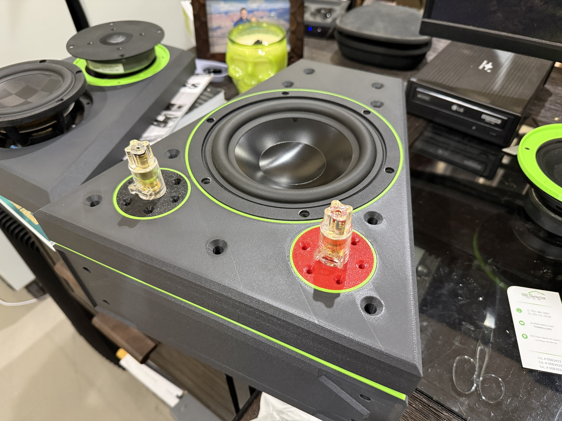
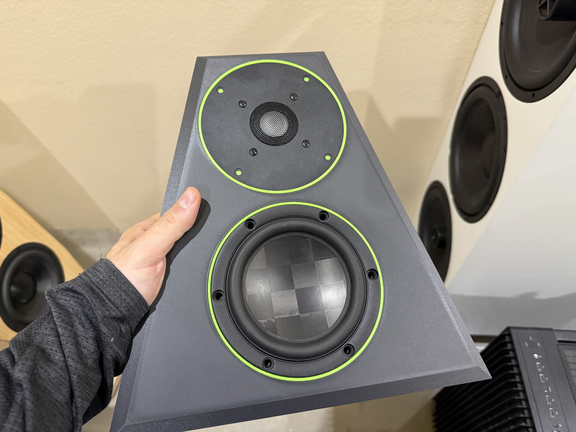
Edit: Satori surround is now complete as well, I’m a big fan of the color similarity of the driver with the Peerless and the baffle itself.
9 Likes
If you can nail the crossover as well as you have with this build (and driver selection) you should have a great little speaker - hope to see and hear it at Iowa, if you can make it.
1 Like
Thank you! Current plan is to be there. Really hoping to get some squiggly lines this weekend to see what I have.
2 Likes
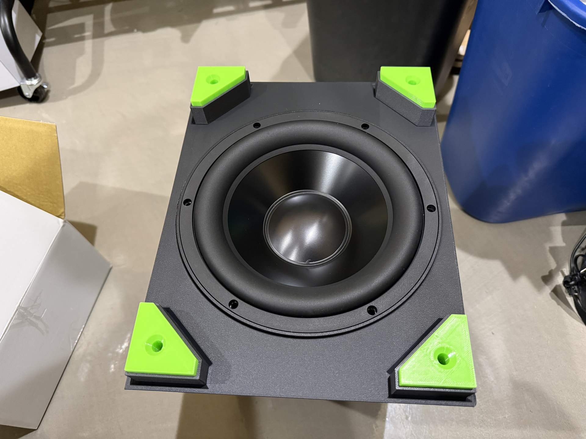
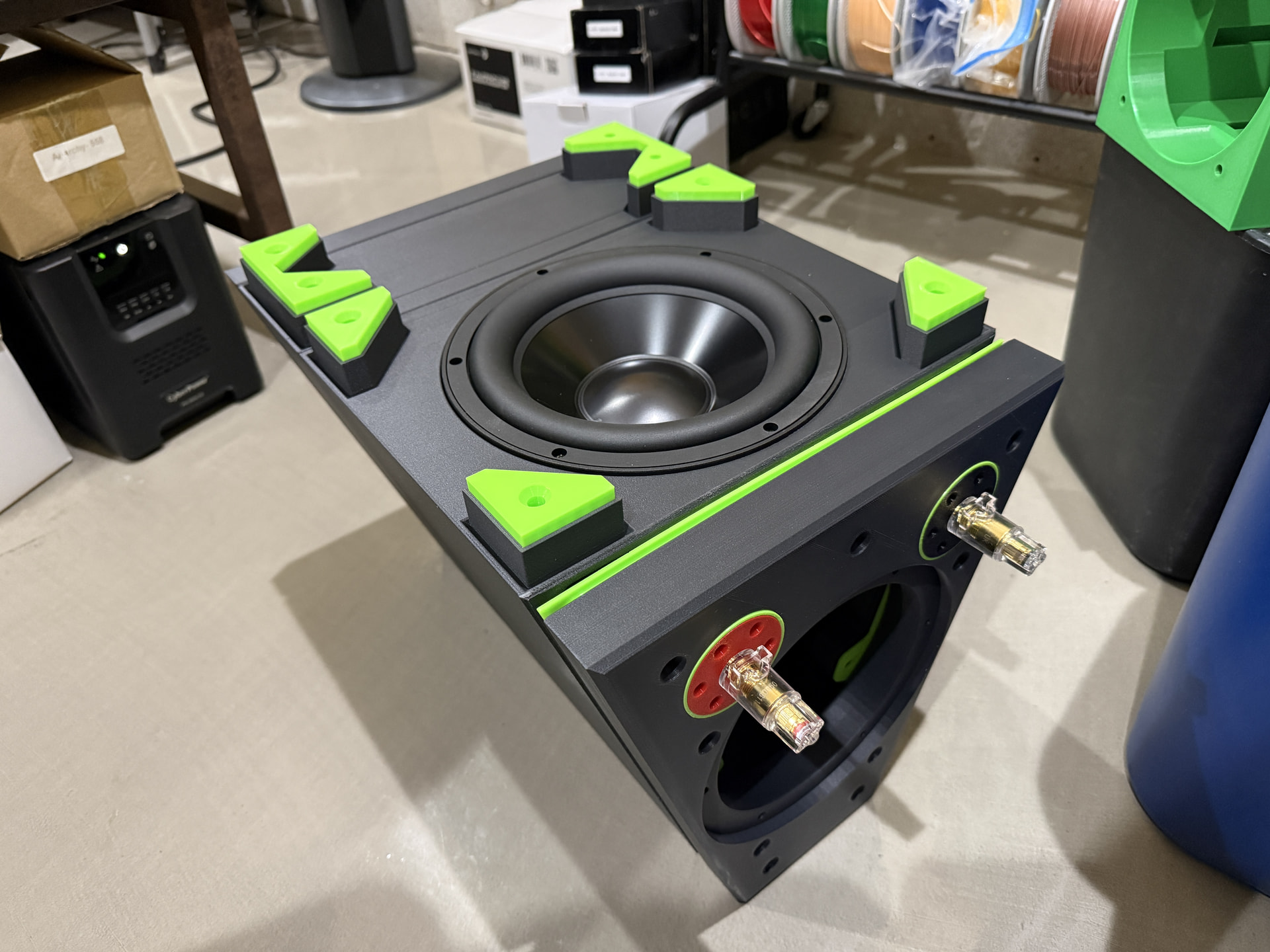
The 3-day print that was the woofer cabinet sides turned out okay. Something is going on with my seals, for some reason they only fit one direction and I’m not sure if it’s the seal or the cabinet. Seal is easy enough to modify but it shouldn’t need to be. Very confusing. Anyway, the cabinet itself needs to be updated a bit so I may have two more very long prints to endure. I’ll probably still use this for testing though as I need to get moving on that.
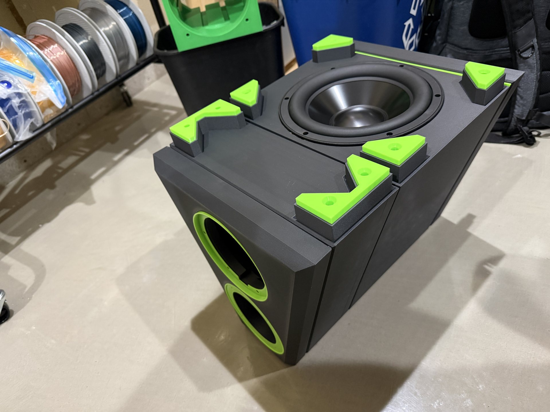
This is not going to be a small speaker. However, with the PR resting there and nothing bolted together, the cabinet feels quite light compared to what I imagine a Baltic birch version of the same would weigh, so that’s nice.
6 Likes
A few unexpected issues:
The unpaired tweeter I pulled from storage appears to be dead, I can’t get anything from it at all. I never tested it when I received it (it was the very last tweeter PE had at the time) so I’m assuming it was DOA.
The bolts I purchased that run from the front of the woofer compartment, through the mid chamber, and into the baffle are too short for the full thing. However, they are sufficient to hold the baffle to the mid cabinet. Those things are 5" long, so I guess I’m ordering the 6" versions.
I did make some squiggles with the Satori and they look reasonably promising. Just a quick and dirty measurement to ensure everything was working once I discovered the dead tweeter.
1 Like
I’ve started measuring a bit to get my head wrapped around what I have here.
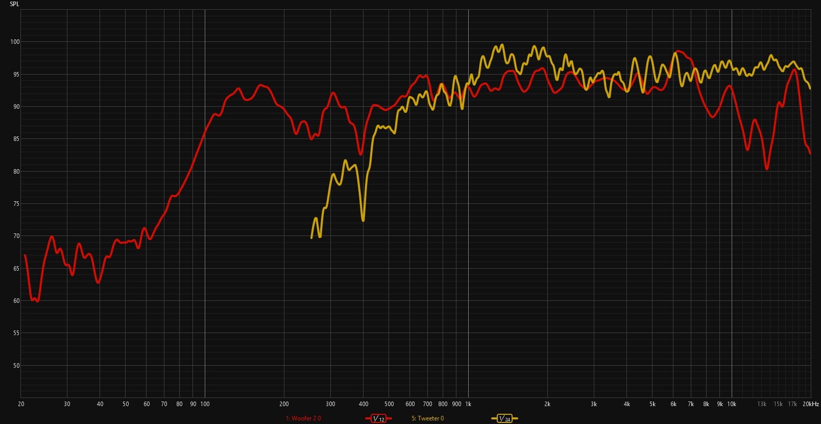
Initial Satori and Peerless combination is shown below. Keep in mind this is a rudimentary setup in a pretty small room - I’m basically just proving my setup is working - and no gating has been applied here either. Clearly a room issue at ~400 Hz, I’m guessing it’s the distance to the concrete floor (which I have no rug or anything placed upon). Probable room issue between 200-300 Hz as well, that would correlate roughly to the distance to the nearest wall. Input voltage was static (but not set specifically at 2.83v), but shows we won’t need to attenuate the tweeter much to get it in line with the mid.
I’m trying to determine how I could maybe get this setup outside.
After this, I got to thinking about how to measure the woofer since it is rear firing. My first thought is to leave the test setup the way it is - about a meter or so away from the speaker, and have the front baffle pointed at the mic. This would emulate how the speaker would actually be listened to, which seems appropriate?
Now, I’m sure the combination of REW and VituixCAD would allow me to measure the woofer directly (woofer pointed at the mic) and handle it via software but I don’t know how to do that being the novice that I am.
Thoughts?
How I would do it.
Andrew actually talks about this a little in this video.
And since we are byilding speakers for us to enjoy in our listenjng spaces I would (and often do) measure a few times in prime listening spots to make sure what I measured at 1 meter is still true at 6-9ft.
2 Likes
Correct. You would measure the woofer just like any other driver using the detailed instructions in Kimmo’s “VituixCAD_Measurement_REW.PDF” file. When you set up the X,Y,Z coordinates, this is all taken care of automatically in software. Be careful, however, when you label the polar angles of the individual measurements. It is easy to get the labels backwards if you don’t think it through. When the mic is pointed directly at the baffle, this is actually a reversed “180 hor” measurement for the rear firing woofer. If you label the measurement that is pointing directly at the baffle as “0 hor”, then the software will think that you mounted the woofer on the front side of the speaker.
2 Likes
Bill - Couldn’t you measure the woofer like it was on the front baffle and use the driver coordinates? Like this:
-
Measure the woofer using the normal angle format (0 degrees when pointing directly at woofer).
-
In the crossover tab, with the woofer driver selected (assuming tweeter is the design axis):
X = 0 (centered on the rear)
Y = distance below tweeter (negative value)
Z = depth of cabinet (positive value)
R = 180 degrees.
^I think this is correct.
Ed, you are correct. My mistake. I forgot about the R value entry when I was typing this. Side mounted woofers would use an R value of 90 degrees and rear mounted would use 180 degrees.
1 Like
Dan , curious what this looks like if you try the above. Maybe a screenshot or two?
Thanks
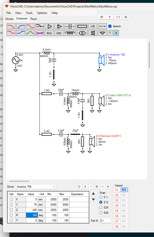
Well I sure can try! See below - don’t mind the crossover, this is just the ‘standard’ 3-way block VituixCAD loads up, no changes have been made at this point (and I still don’t have a woofer response to load in yet, hopefully the bolts I ordered will arrive today so I can begin assembly of that cabinet).
Today is all about modifying the exterior skin in CAD to (hopefully) reduce the shrinkage that is creating some unattractive corner seams. You wouldn’t notice it from afar, and I don’t think it would quite impact the gasket seals, but I’d like to reduce the issue as much as possible.
I appreciate all the support by the way. I’m running out of time!
Edit: The Peerless should be set at 0,0,0 in that screenshot.
Edit again: Is ‘T’ for 'tilt"? Like, if the woofer was downfiring would that be set to 90?
Yes, “T” is for tilt. I think downward facing would be NEGATIVE 90 degrees.
Well I (sort of) figured out why the gaskets aren’t lining up perfectly. Somehow the cabinet is not entirely symmetrical, it’s off by at least 1 mm, maybe more in some areas. I’m unsure where the error began which makes it difficult to fix without remodeling the whole thing in CAD. So I’m at a crossroads - do I remodel the whole thing (probably a full day+ worth of effort) or just live with it as-is?
That’s a hard call to make. We are all overly critical of our own creations, but “normal” people would probably never notice the difference. I deal with that every day here at work. Little things that the client or my boss just doesn’t see, but I can’t send out the door looking like that.
2 Likes
If the error is that small and doesn’t affect performance, you live with it. Then you find the source of the error and ditch your previous CAD work, if that’s the problem, and start anew working at your leisure. It sucks, but if people only knew how many fabrication and assembly errors we’ve all made but recovered from. 3D derivations aren’t immune, apparently.
1 Like
In the interest of my sanity I’ve started development of a new cabinet. There are a few other changes I had wanted to make that would have been very difficult without recreating it anyway, so here we go again.
4 Likes