Thought I would share this. It is interesting and measurable.
This is from the “Transformer and Inductor Design Handbook” by Col. William T. McLyman. He designed transformers for Mariner and other spacecraft. Good news: he did all of the calculus for you. Bad news: it still requires “very” careful reading and formula figuring. The text is available on the web as a free PDF but is a basic scan. The book is much more useful than the scan and highly recommended if you are interested in electromagnetics. I got into this while building high voltage power supplies and Tesla Coils.
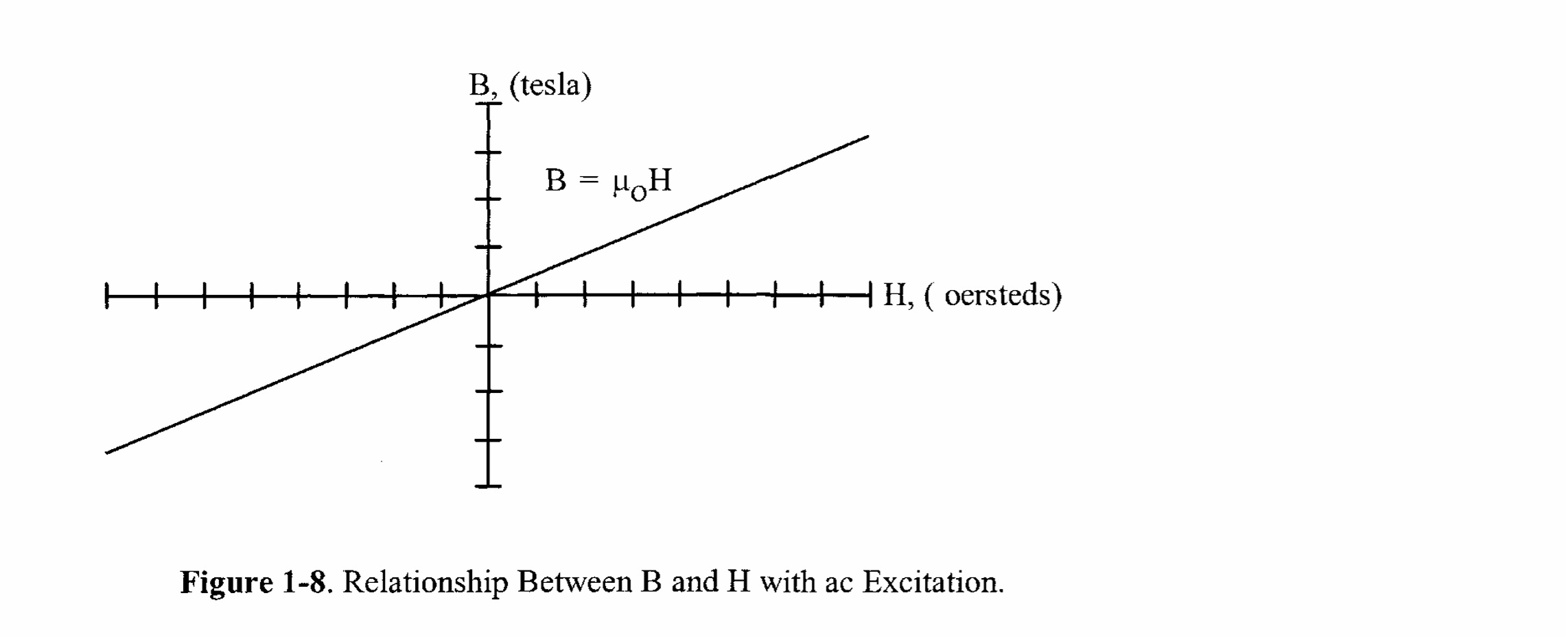
Here are some BH Loops for Solid core materials. First, an air-core inductor has a permeability of 1. In other words, they have a 1:1 ratio of B/H. This is why they’re desirable - they are linear. Limits are power handling and DC resistance.
Here is an Air Core BH loop.
There is no such thing as a perfectly linear solid core inductor, but some are more linear than others. Both non-linearity and Remanent Flux (tendency to “want” to stay magnetized after current is applied) affect all solid core inductors.
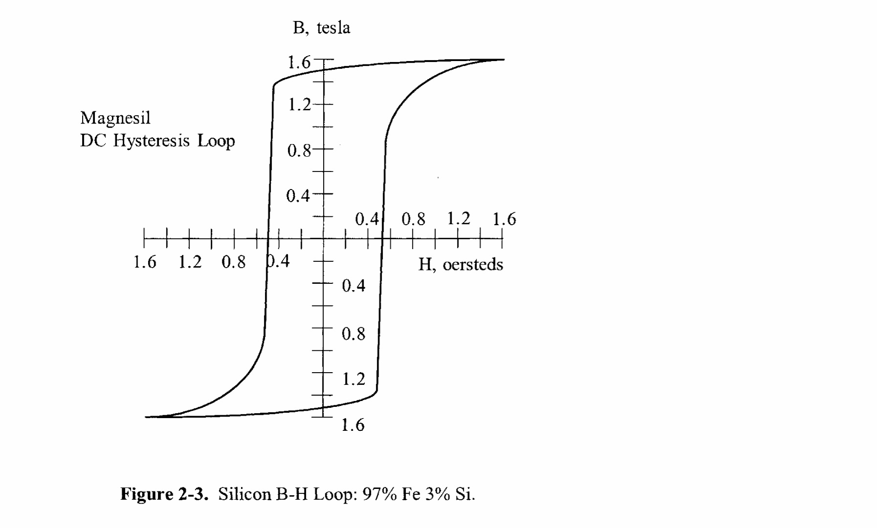
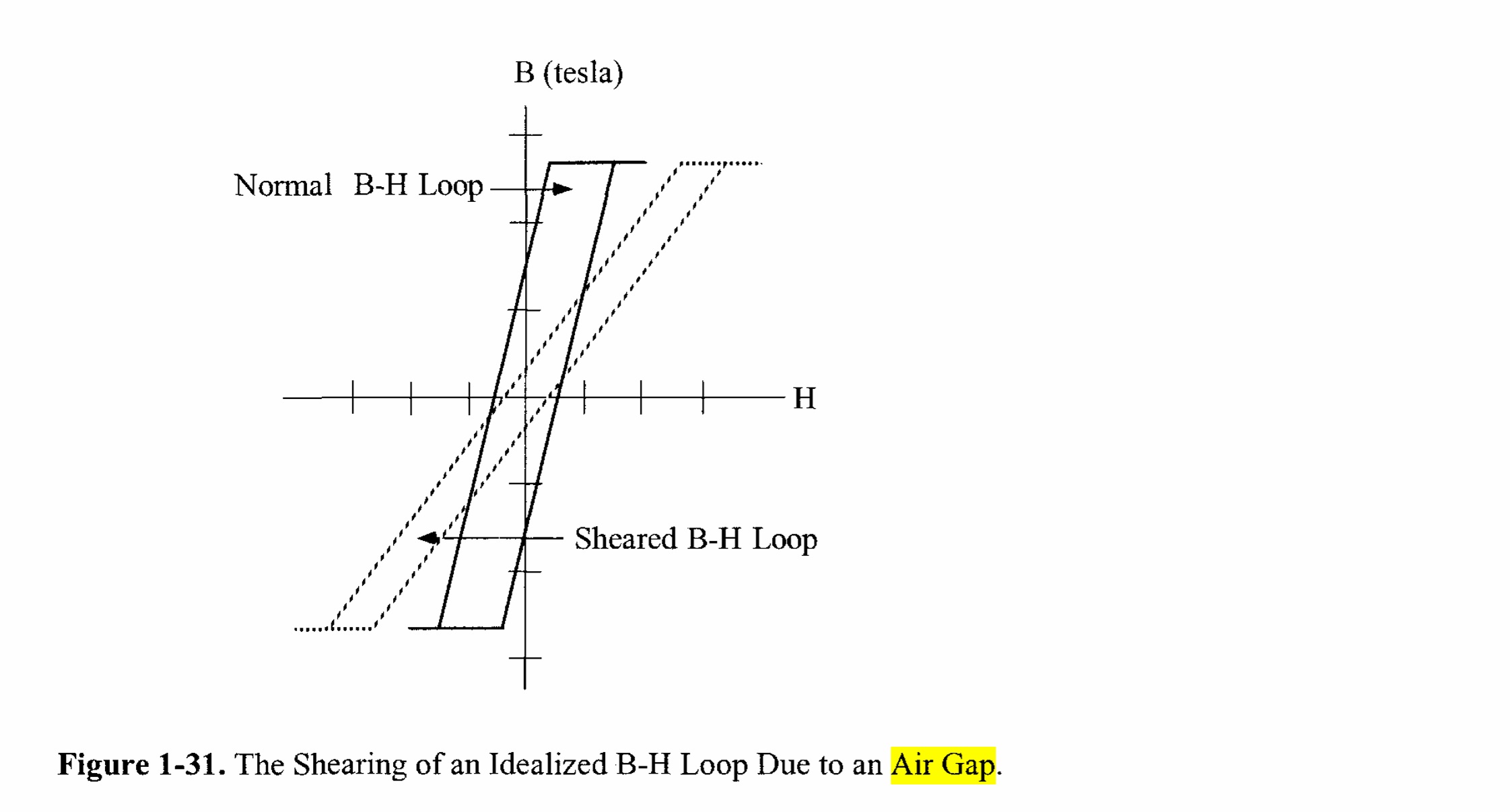
Below is a bar-core (Silicon-Steel) inductor. The pic below doesn’t account for the much-reduced permeability of a bar core. The Air Gap is essentially equal to the length of the core. This shears the curve way to the right and makes the straight portions of the curve more diagonal. It gives more of a linear area at the expense of a little efficiency.
If you push enough current through it, you increase H to the point that it starts to work in the non-linear area of the curve. Distortion. Silicon steel also has a tendency to hold “Remanent” Flux. This is what separates the 2 portions of the loop. It takes time for the core to switch from positive-going to negative-going.
Effect of an Air Gap on a BH Loop
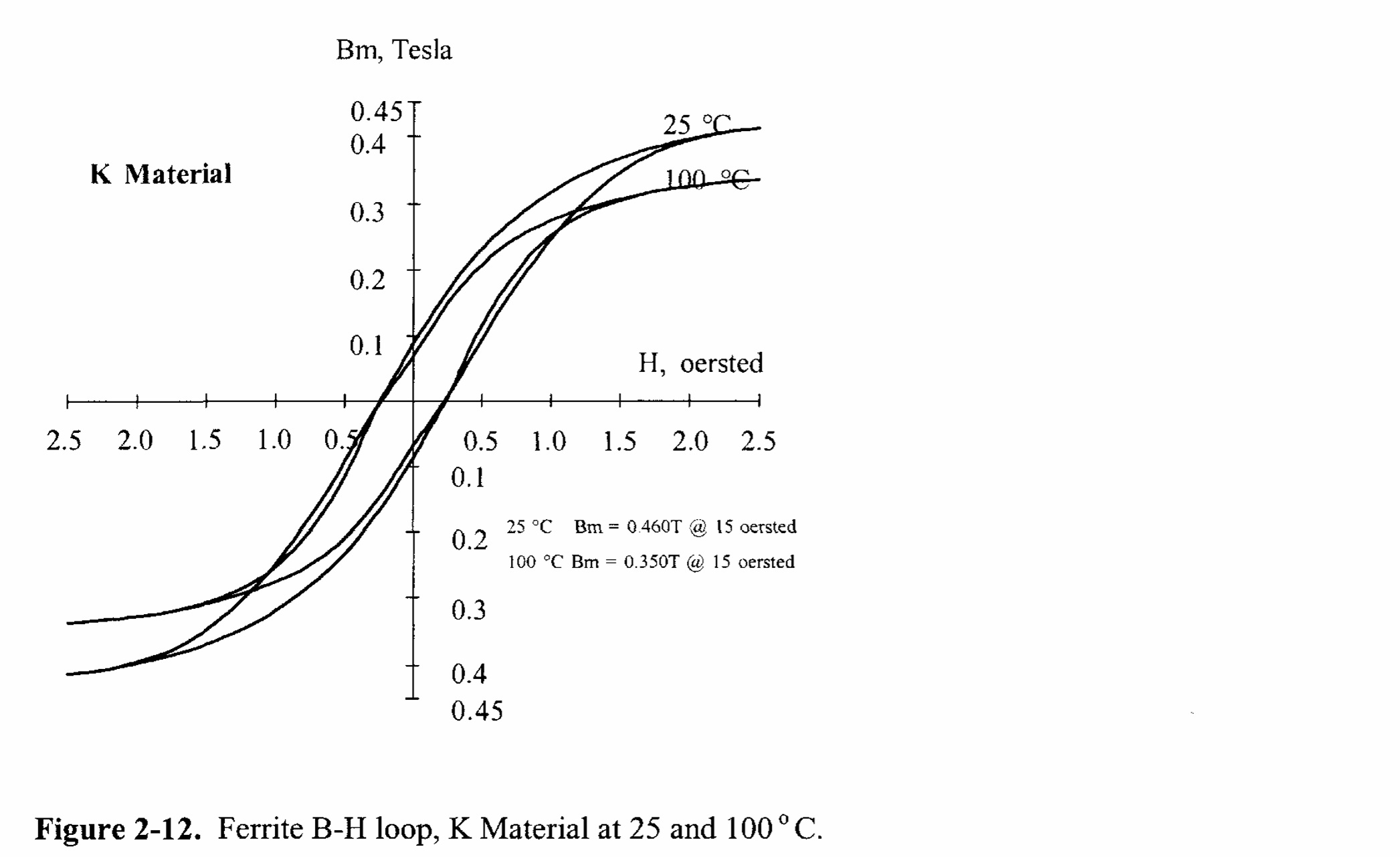
Next is a Ferrite Inductor. These have a very high frequency response at an expense. They can run in the hundreds of Khz but aren’t very linear. They can also be inefficient at low frequencies. Not audio grade IMHO. Good for high voltage / high frequency stuff!
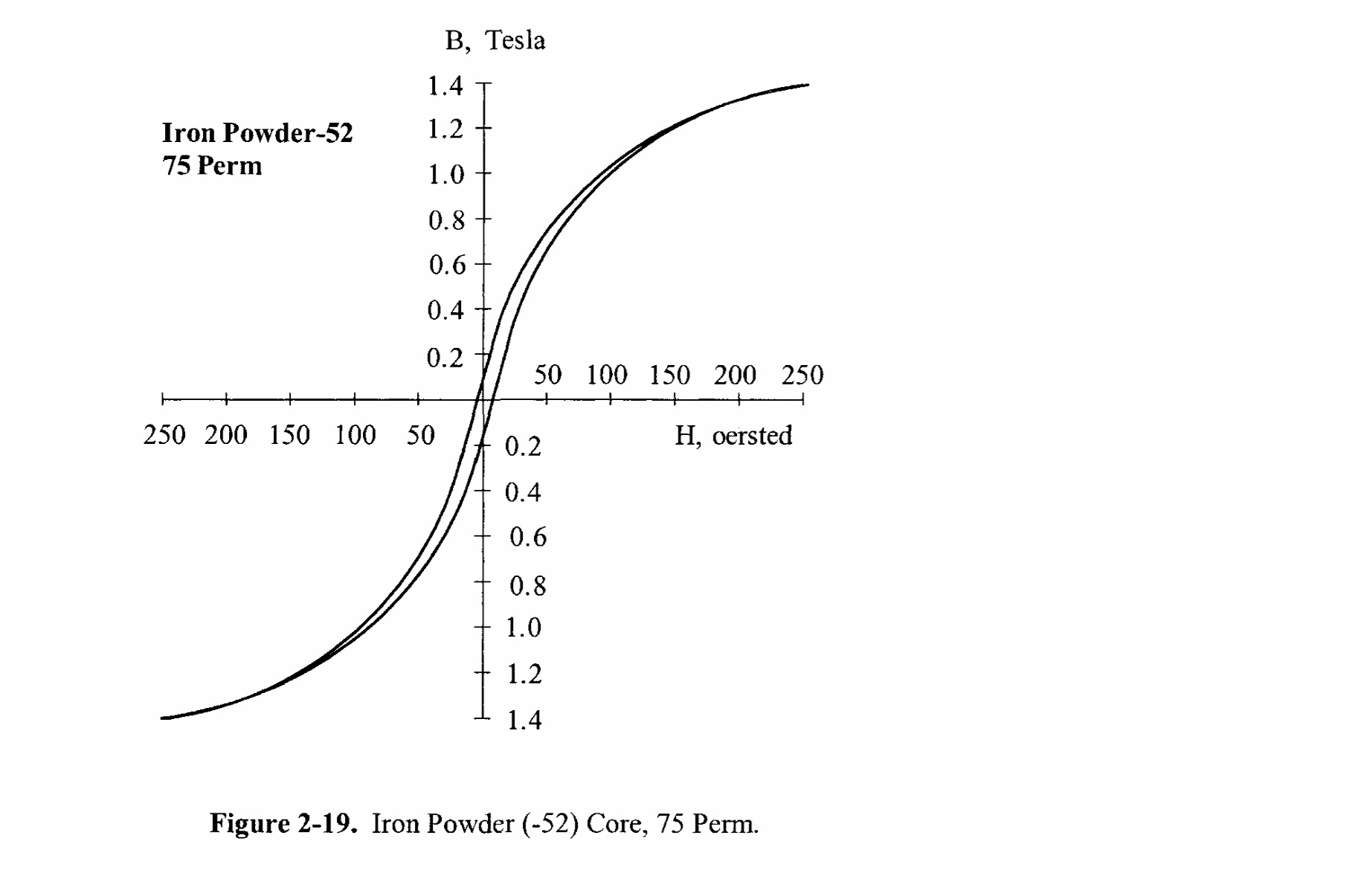
Next is an Iron Powder Core, or P-Core. Again, the BH loop will be shifted to the right and will increase the Linear region. Note the gentle “knee” of the curve into saturation.
Here’s the most interesting one to me. This is a Kool-Mu, or “Sendust” core. It has the least Remanent Flux (almost none) and is quite linear. It also has the same gentle saturation characteristic of the powder core. Again, the curve will be rotated to the right by the large Air Gap.

Based on all of the above, I would choose either a Bar-Core or P-Core. A Kool-Mu Powder core, properly designed, would be a nice option too.
Cheers / Robert