Ok, VituixCad idiot braving another post where he will be labeled an idiot.
Since one of the goals in the VC process is a certain “tilt” to the off axis power response, and that is very dependent on the baffle and driver layout, how can you determine if your proposed design will work in the end?
Seem like you would need to take the manufacturers infinite (or IEC) baffle measurements, apply a baffle diffraction program transform, design a possible crossover, then finally you can see what the power response is.
Can that all be accomplished in VC, or do I need separate programs?
Is that about right?
Seems like a lot of modeling up front and the payoff is less work later, and no “turkey” speakers.
Is that about right?
You are not alone. I have been working on this problem for several years now and cannot find a good solution. But I keep looking. Best I have come up with so far is to build a prototype, mount and measure the drivers individually. Then look over the actual directivity profiles in VC and take my best guess as to what to do. I simply find it impossible to model everything up front to avoid mistakes. And I have made alot of mistakes.
1 Like
Personally, I don’t think mfg or IEC baffle measurements with a baffle diffraction program will get you close enough. Too many variables. I think you need to build a prototype and measure. Then use VC to look at the balloon response.
I think even without mfg curves for specific drivers, you could model the baffle, driver positions, and driver’s sizes and get useful results on things to avoid. This could narrow down the prototype you need/are willing to build.
For example, you could see the challenges of a two-way with 10” woofer and 1” tweeter on a rectangular baffle with no edge treatments.
I’ll try to work up an example tonight or over the weekend if no one beats me to it.
1 Like
One other thing I would add…although just semantics. There are no “goals” in VituixCAD any more than a goal in Jeff Bagby’s PCD is to design LR2 filters vs LR4 filters. VituixCAD is just simulation software.
However, it does explicitly account for off-axis behavior (if you input the off axis measurements). The goal of a certain “tilt” comes from other research by Toole, Olive, and others. These “tilts,” or target slopes, can apply to the Listening Window, Predicted In-room Response, Sound Power Response, Directivity Index, etc.
Attached below are notes that the author of VituixCAD put together to help interpret some of the curves for speaker reviews, but these are not goals of the author or VC, but more of a literature review. But it does summarize the appropriateness of some target curves, like the tilt of the power response.
Speaker Review Feedback.pdf (750.5 KB)
3 Likes
This is actually a very good question. The answer is not simple simulation, but a combination of studying existing designs and experience in understanding the many acoustic aspects.
If I were to ask you, after you decide on your goals for on-axis and listening window flatness, PIR slope, SP slope, etc. How much error or deviation from that goal are you willing to accept? I’m guessing that many don’t know exactly what it will sound like until they hear it, so how do you decide on how good is good enough from looking at the charts? If you can’t interpret the chart then its not a useful chart. Is the goal a “good speaker” or a “great speaker” or a “perfect speaker”? So the question isn’t really “will it work” as any speaker that makes sound effectively “works” but rather “will it meet my expectations”?
As far a overall impact of design elements, there are many aspects that can be “simulated” to aid in learning, but some is also best to be experienced in the real world. Are you willing to building multiple baffles to compare the results? Are you willing to redesign with a different driver? It’s all a balance of how much work and cost you want to put in to chase that acoustic dragon.
For simulation, it’s easy to view the difference / impact of a wide baffle vs thin baffle, the difference between driver sizes, even the difference between driver separation, crossover slope and crossover frequency. Other aspects can get a bit complicated - what about waveguides, horns, ribbons? what a bout dipole vs monopole? The list goes on.
Some experience can be gained from studying existing speakers, and especially from studying your own. There’s plenty of “spinorama” data out there, with some knowledge of types of drivers, baffle size and shape, and some knowledge or assumptions of crossover implementations, a lot can be learned from studying existing designs. For example, Kimmo recently posted this chart along with some of his own opinions of the merits of the speaker designs.
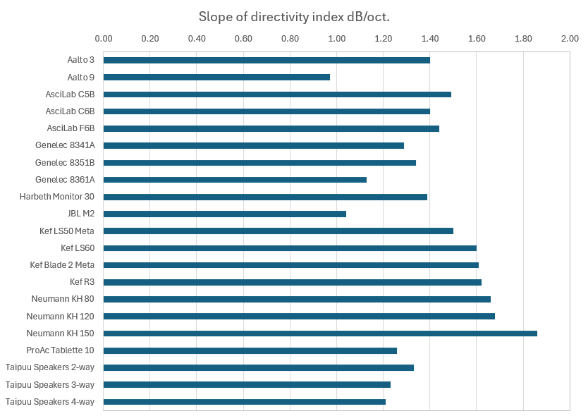
source: VituixCAD | Page 238 | diyAudio
2 Likes
Thanks Reet - I’ll have to dig into the VC big manual. I know that I have built some great sounding speakers (Specifically, off axis “blooms” in certain frequency ranges) So now I want to avoid building several box/baffles before I am ready to “build final”
Thanks for the Notes. To me, semantics are always important. Understand about the tilts and rolloff/octave, but my concern is mainly to have a smooth power response over the whole FR from bottom to top.
1 Like
Sigh, that’s what it looks like. Build a prototype.
What am I doing wrong? I am attempting a 3 1/2 way and V Cad will not recognize my fourth driver which is my low woof. I think that I have tried everything. It is visible in driver layout. It is visible on the XO schematic. It loads the circuit but is does not show up on Either the SPL panel or the Impedance panel.
You’ll need to show your work, or send me your project files. VituixCAD includes a nice project archiver tool, as long as you have 7zip installed. File Menu→ Archive project. It expects 7zip to be installed in C:\Program Files\7-Zip\7z.exe, change that in the options if you need.
Thank you. I appreciate any help. I will attempt to figure out your words with the help of my wife. She is my IT Specialist. I sometimes feel like a genius for marrying my wife, but often times not.
1 Like
That is a failing of mine
Download 7zip here:
Install it, then restart VituixCAD and the archive project button should be available to you. It will create a zip file that includes your project file and associated driver response and impedance files. The zip file will be saved in the same folder as your project file.
Fixed it !
Here is the silly thing that I did that caused the problem for me. One of my crossover variants did not have a driver#4, the low woofer, or BSC woofer because I combined the two drivers and created some frd files with a filter on the low woofer included. VCad did not like that one of my crossover variants was missing a driver.
@raddon - answering you here rather than in Eric’s thread.
For crossover design work, you measure the raw drivers at 1 meter. With 8 foot ceilings, if you are able to center at 4 feet, your farfield measurement will be meaningful down to somewhere between 215 and 400Hz. If you merge with your nearfield in that range, that is quite typical.
When simulating, you set the listening distance in the Options, but 2 or more meters is normal. The only time you need to measure further than 1 meter is if you are trying to validate your simulation vs the actual measurement. You have two options: (A) Measure at 2 meters, in which case your farfield is only going to be valid somewhere between 300-600Hz with 8 foot ceilings. For a two way, this probably gives you enough information to see if the sim is matching reality. Or (B) Set the listening distance in the options to 1 meter and measure the actual speaker at 1 meter, and compare simulation vs actual.
2 Likes
This isn’t a tip or trick, but a VCAD Merger question that has nagged me for some time. My question concerns the Merger “Force to Gradient” option. I generally understand how it works, but am not sure when I should use it. From the VCAD help file:
“Force to Gradient’ checkbox and ‘Monopole portion’ text box enable forcing ideal gradient directivity to near field LF responses if directivity of far field HF responses is too unreliable at LF due to window function or measurement conditions, and directivity at LF can be predicted without measurements.
Monopole portion values for known gradient radiators: Omni 100% (DI 0 dB), Cardioid 50% (DI 4.8 dB), Super-cardioid 37% (DI 5.7 dB), Hyper cardioid 25% (DI 6.0 dB), Dipole 0% (DI 4.8 dB). Directivity of far field HF responses is used at LF when ‘Force to Gradient’ is unchecked.
Highest frequency using ideal gradient pattern is adjusted with ‘below Hz’ text box. Directivity is blended within ideal gradient range and transition frequency. Narrowest blending range is one octave.”
That explains the general operation, but I’m left with these questions:
-
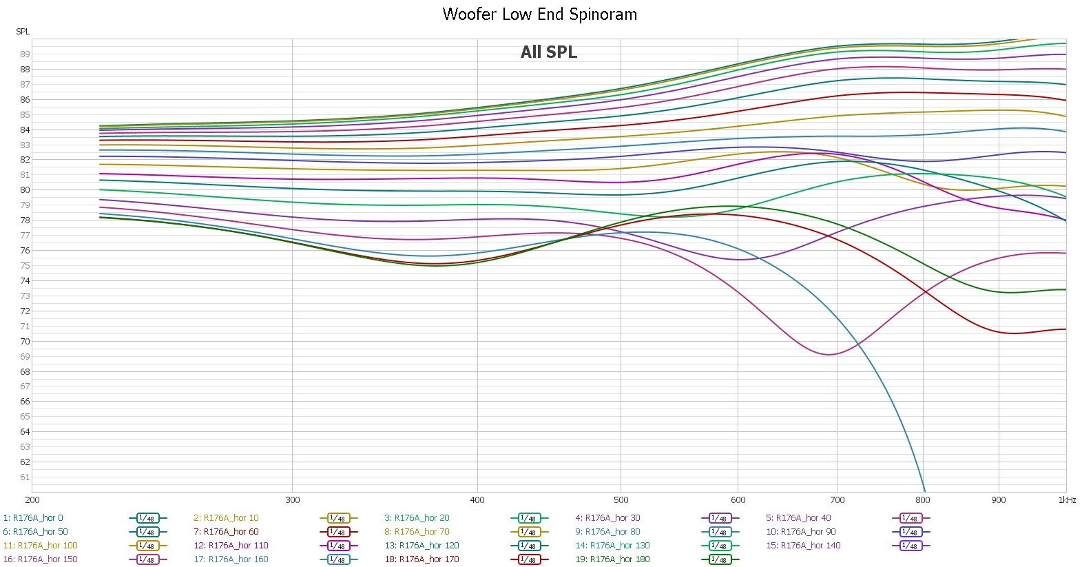
How can I tell if the directivity of my far field HF responses is too unreliable at LF? In my test setup I have to window at about 4 msec (250 Hz) to avoid reflections. Is my window so short that it qualifies as unreliable at LF (see the picture of the expanded low end of one of my woofer spinorama responses)?
-
What determines if the directivity at LF can be predicted without measurements? My builds typically have standard, circular drivers on flat baffles so I assume I’m good.
-
Do I select the “Omni” option at 100% when using standard, circular drivers on flat baffles?
-
What determines the highest frequency to be used?
I suppose I could use the after the fact method. In that scenario I wouldn’t initially use the Force to Gradient option. Then I would look at the power response and directivity polar map to look for irregularities at the lower frequencies. If problems are found I would then repeat the merger with Force to Gradient selected. But in my concrete–sequential mind I feel I should be able to pre-determine if I need to use Force to Gradient.
I did find some additional information on Force to Gradient from kimmosto (VCAD author) over at htguide VCAD forum: LINK. It discusses some of the settings kimmosto uses. YMMV. I believe @A4eaudio has some experience using it too. Maybe he’ll chime in.
1 Like
I’ll post some links to the discussion that led to Kimmosto’s post. Probably tomorrow, as I am travelin..
Ed,
I don’t have specific answers to your questions, but I think the following will help a little. My issue with force to gradient, which led to Kimmo’s post was as follows…
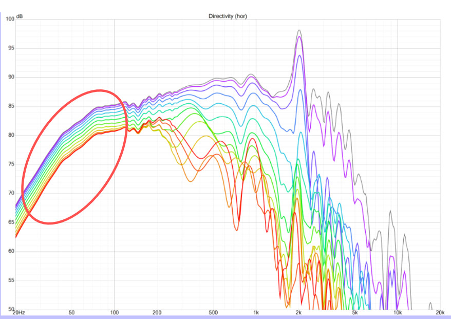
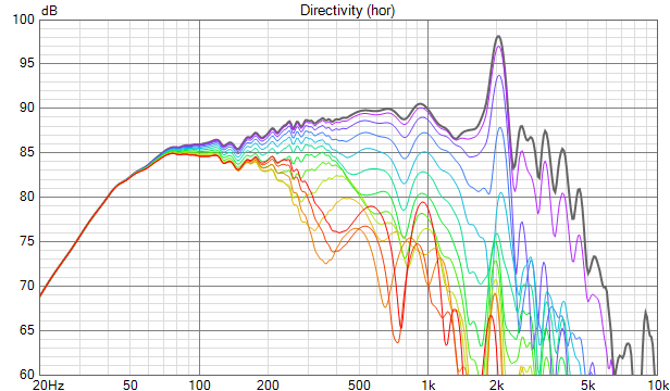
I posted merged measurements of the woofer HERE - See PIC 1 below. This is a group-project of sorts, so there are several people looking at the data and helping out. One user (hifijim) noticed how the polar line graph data was NOT converging together at very low frequencies, whereas we would expect the woofer to be acting omni-directional very low. There is a good conversation that follows that post for a few pages.
PIC #1:
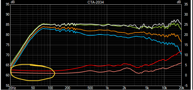
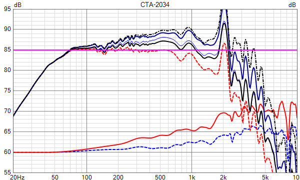
@reet posted on HTGuide and showed another way we could see the issue was that the Directivity Index did NOT approach zero - it approached 1dB below 300Hz and then actually rose a bit above 80Hz. PIC 2 below.
PIC #2:
PICS 3 and 4 below show converging polars and DI approaching zero as we would expect. Hifijim’s rule of thumb was to use force to gradient at 40Hz (on woofers and midranges for a 3-way)(see his post #1,382) and this is what PICS 3 and 4 below show. The force to gradient option is sort of a “band aid” for measurement errors and originally Reet did not use it at all, but later in post #1,467 he used force to gradient at 30Hz with 95% monopole portion.
PIC #3:
PIC #4:
Going back to your questions…in this case this issue seemed to be a result of a combination of factors - wide baffle, large woofer, and sealed cabinet. I have not typically used force to gradient and have typically got reasonable results of the polar line graphs converging and DI approaching zero. So I think if you keep on eye on those two illustrations, you’ll have an idea of whether you need to worry about using force to gradient or not.
1 Like