Not really a “Tip” or “Trick” but thought I’d start a VituixCAD thread like the one on the old site.
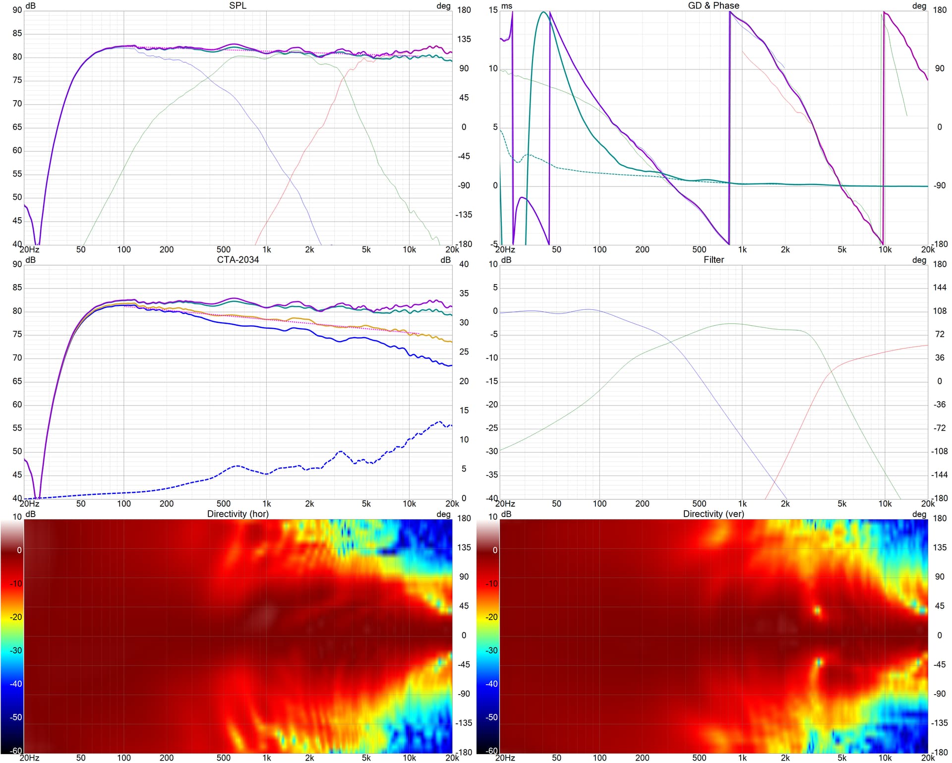
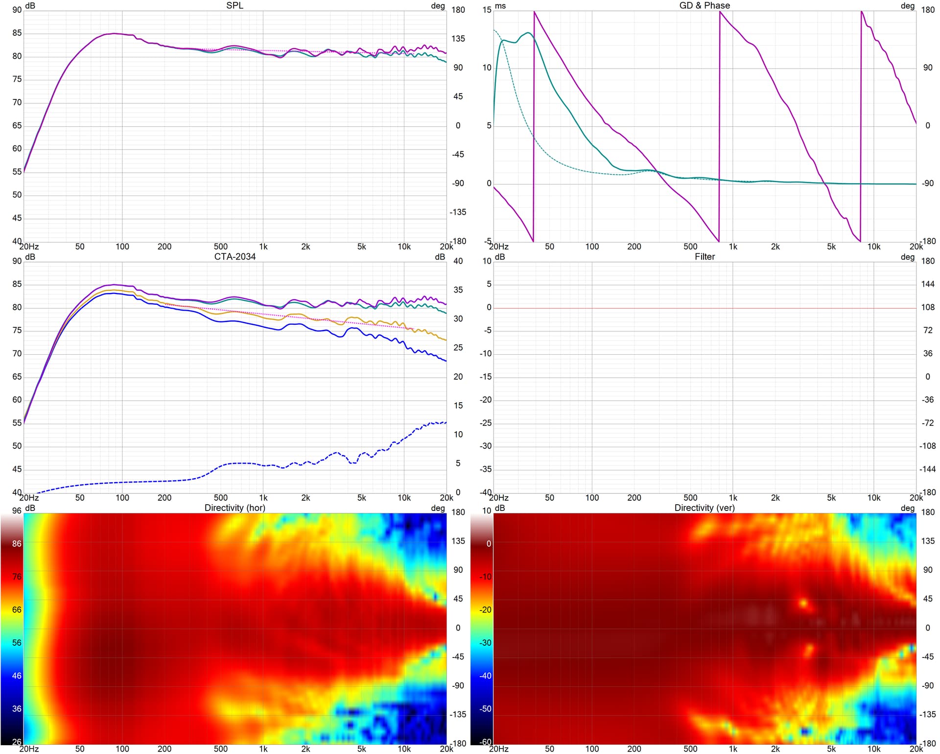
First 6-Pack is simulation. Second 6-Pack is measurements of actual completed speaker.
I have to check measurements and merging to confirm what my SPL below 100-150Hz looks like. My guess is that the “Actual” is accurate and I need to bring the 4dB bump down.
Tip: Toss the USB mic and get a real XLR mic and 2-in USB Audio interface for loudspeaker measurement.
Tip: A “jig” is not necessary to get started measuring with a timing reference in a “dual-channel” fashion. All you need is a patch cable connected from output to input on your audio interface.
Tip: Forget about min-phase and timing guesstimates.
Tip: RTFM and Measurement guide for process of measurement and merging
For those with a USB interface that enables phantom power on both channels with just one switch, is there a risk of damaging the loop-back output circuit?
Recommend checking with TRS connection on a multimeter. For all USB interfaces that include combo XLR and TRS input plugs, I’ve yet to encounter one that provides phantom power on TRS, so you use XLR for mic input, TRS for line input.
Farfield in garage with 10’ ceilings. 4.55ms gating gets me close to 200Hz. Merged with nearfield somewhere in the 225-275Hz region. The VituixCAD merger tool is really quite accurate, using separate diffraction files for nearfield (diffraction simulated at 5-30m), farfield (@1m) and adding delay for the port.
I will measure mic-in-box and probably ground plane to really get a good grasp of what the true low-end is doing.
Dual channel with XLR mic and Motu M2 interface. No need for min phase or acoustic offsets. Note how accurate the sim was…the simulation is using the measured phase of each raw driver at 1m whereas the actual is the real measured phase of the completed speaker at 1.5m.
Talaria studio monitors (yellow speakers from InDIYana, that were white at SDC). I think the new XO is much better, but we’ll see what the consensus is in Detroit.
So the simulation is using measured response at 1 meter with a simulated crossover , and the actual is using measured response at 1.5 meters with a physical crossover?
If they match (as they should), that is what I have always wanted….
Every once in awhile (i.e., often) my actual measured result doesn’t match what the XO simulation software predicts. Always due to some user error on my part.
I usually measure on axis and maybe on or two off-angle samples and if I’m close to the sim then I assume the full Spinorama suite is close enough.
This time I did a full 360 degrees horizontal and vertical in 10 degree increments to compare the actual speaker to the XO software simulation.
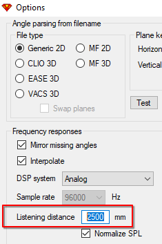
TIP: Change listening distance to measurement distance for comparing final simulated result to measurement of final result. Remember to change it back to 2500mm+ for design work at actual listening distance. In the Options window:
You should design using the approximate listening distance, to compare your measurements with xo in place, you need to match the listening and measurement distance.
No, the listening distance should match listening distance, 2000mm is minimum for CTA-2034, for most speaker beyond 2500mm doesn’t make much difference. 1m design is not great, especially for large speakers. And you’re right, summations can/will be different, hence the aforementioned tip.
You put in the intended listening distance in VituixCAD Options. Per Reet, 2 meters is the minimum. 2.5m is default (?)
To confirm that the actual speaker is consistent with the simulation from the software, measure the actual speaker with xo in place at the same design-distance you put into the Options.
If you measure the final speaker at 1 meter, which may seem logical given that your Raw Driver measurements were at 1 meter, it will NOT match the simulation because VituixCAD has accounted for the wavefronts interactions at the greater distance. When I first began using VituixCAD I made this mistake and thought I had messed up something because my actual measurement was not matching what VituixCAD predicted but once I measured at the correct design-distance I in fact had put everything together just fine. In my example of post #1 I am designing a nearfield monitor so designed with 2m in the Options and measured at 1.5m because I couldn’t do 2m in my garage.
Measuring closer at ~1m should make a bit more sense than trying to gather a good reflection free measurement at 2m distance in-room. Just change listening distance to measurement distance for comparison for validation. That was the tip…