Figured I’d post these up to see how the image loader works.
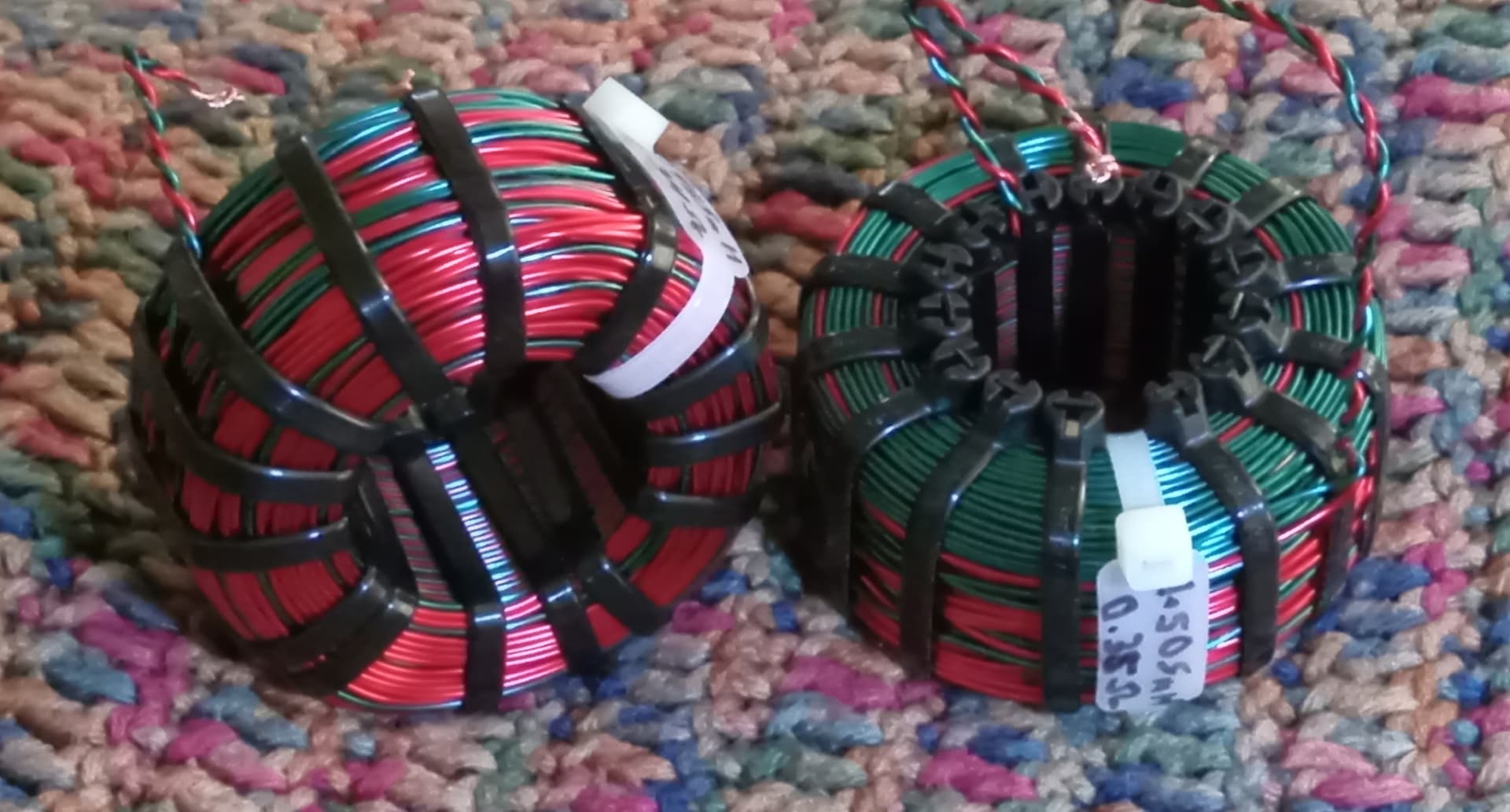
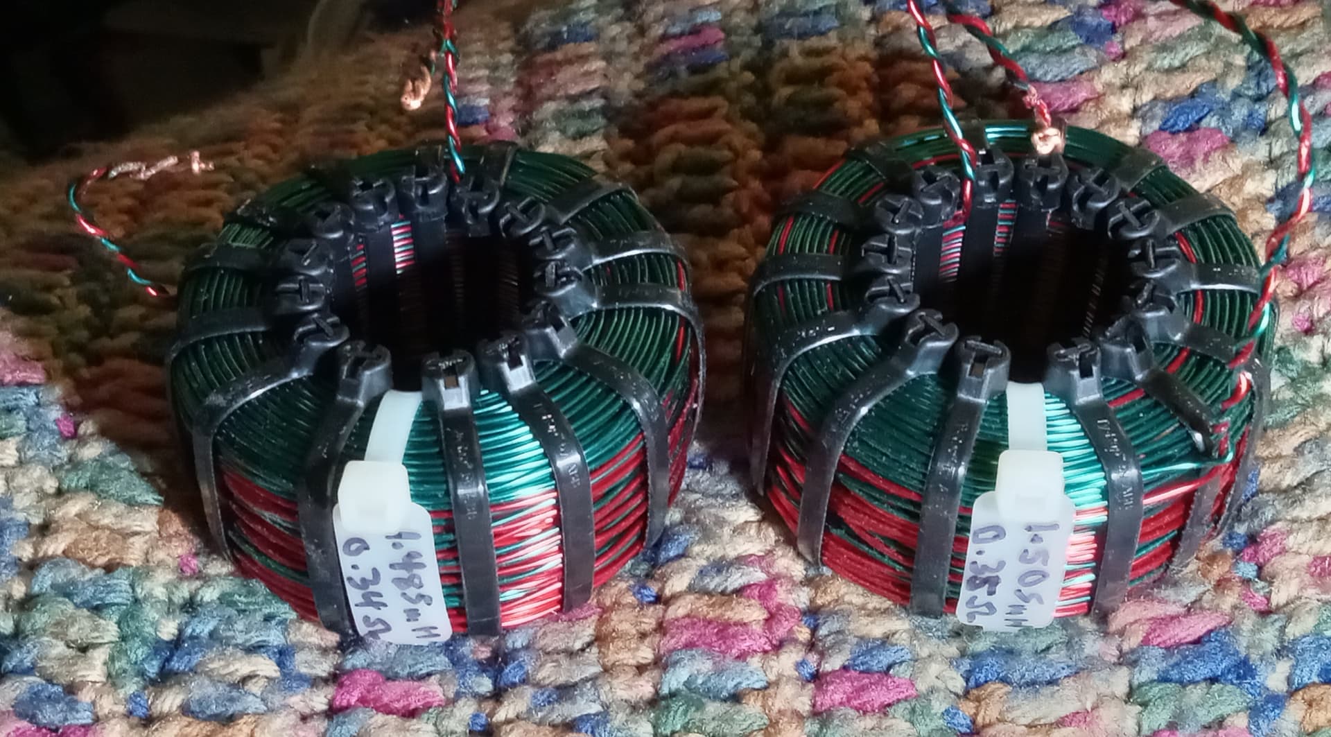
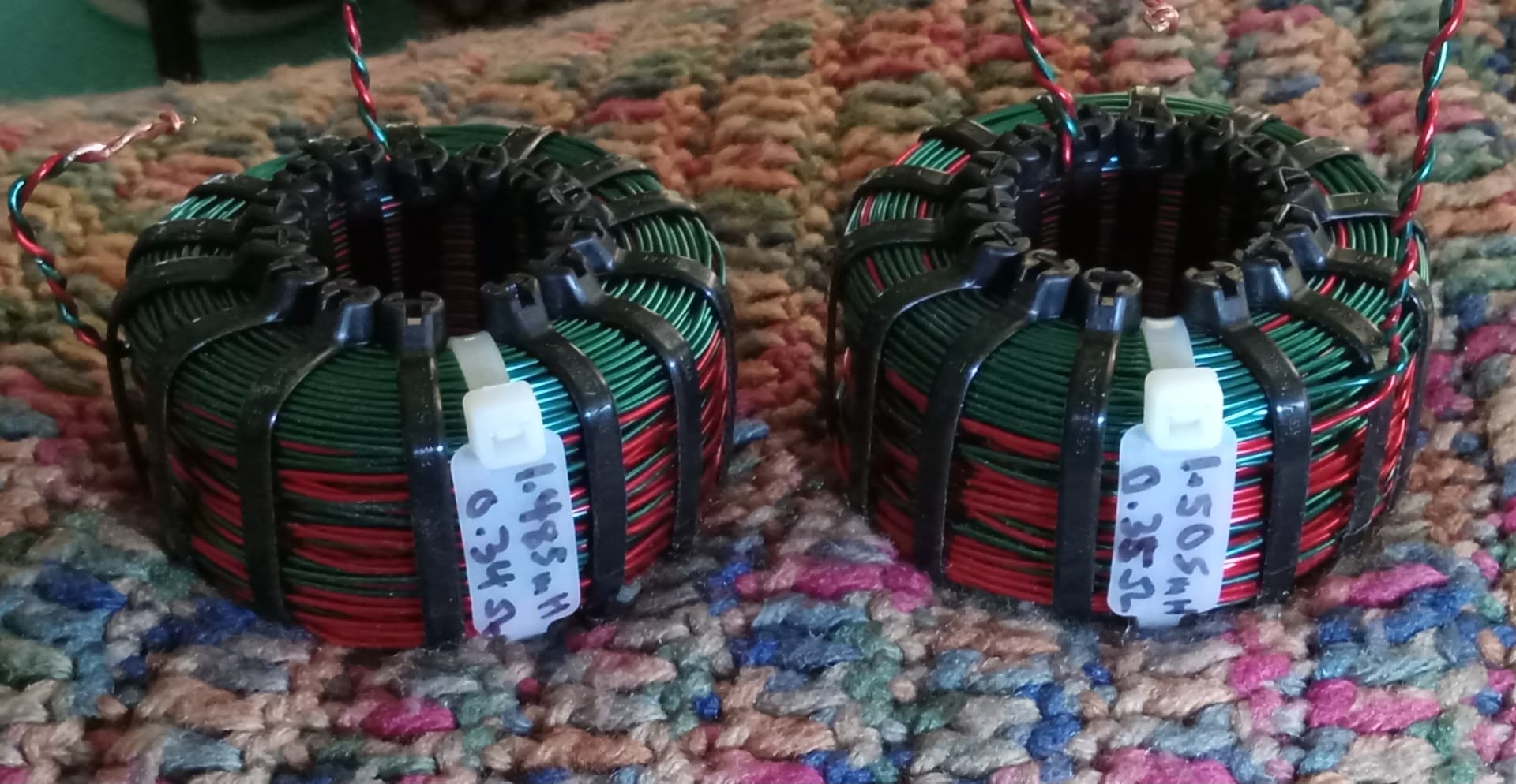
I’ve wanted to do a pair of bifilar coils for a bit, but bever before had 2 spools of the same gauge. Since I had a spool of “blue (dry-oil)” [looks teal in color] and another of red, both 18awg, I thought why not?
However, I learned some things too. I was shooting for a 0.75mH coil on both, targeting a lower DCR than with single wound 18awg. The DCR is comparable to that of a 14awg coil, so that was a win, especially since they were twice the value expected.
Turns out (pun intended), that paralleling coils on a xover board is not the same thing as winding 2 interleaved coils against the same bobbin. I wound and measured for 1.5mH on one of the 2, thinking paralleling would halve the dual values to my target of 0.75mH. Since it is the number of turns to make inductance, no matter the gauge, just paralleling 2 strands does nothing except halve DCR and double the cross-sectional area of the copper strand over that of a single.
Yes, I should have known this already, my hunch was wrong.
It makes me wonder if then using 2 coils in parallel and placed close, would the inductive coupling allow them to act as my bifilar coils do? Maybe not to their extent not being interleaved, but I may have to play with a set and see.
It’s one thing to know best practices, and another to find out for yourself.
I had to google “bifilar” and look at your coils several times to understand. It looks like the teal and red wires are wound parallel to each other as you wound the coils. Then the teal and red wires are twisted together, but only where they enter or exit the coil. The reason the top of each coil looks all teal (instead of alternating teal and red) is because there is another red wire running parallel just below it. Looks cool!
I have admired your work for many years, and love your experiment here ! I also really like the idea of Bifilar coils. If the insulation is reliable/sufficient, there should be terrific signal transfer from 1 winding to the other winding. It feels like safety is the primary reason for interleaved windings - with an intentional layer of film between the windings.
It feels like Tom S might have some history with failed bifilar coils or the potential for this.
Sadly, it’s beyond my scope of expertise. I did have some strange Italian transformers I picked up years ago that were advertised as such, but you never really know when dealing via eBay.
Where do you guys buy the wire? Every time I have looked at wire, it wasn’t cheap enough for me to want to wind my own coils. I would only save ~10-20% of the cost of bought coils.