Ah, I have the version with the backup. Nevermind.
That shouldn’t make much difference. The chamber I created with my mounting procedure is probably very close to the back cup version.
I’m extremely interested to hear these this event. Last interesting planar I heard was Scott Sehlin’s “Matrix” and that was forever ago.
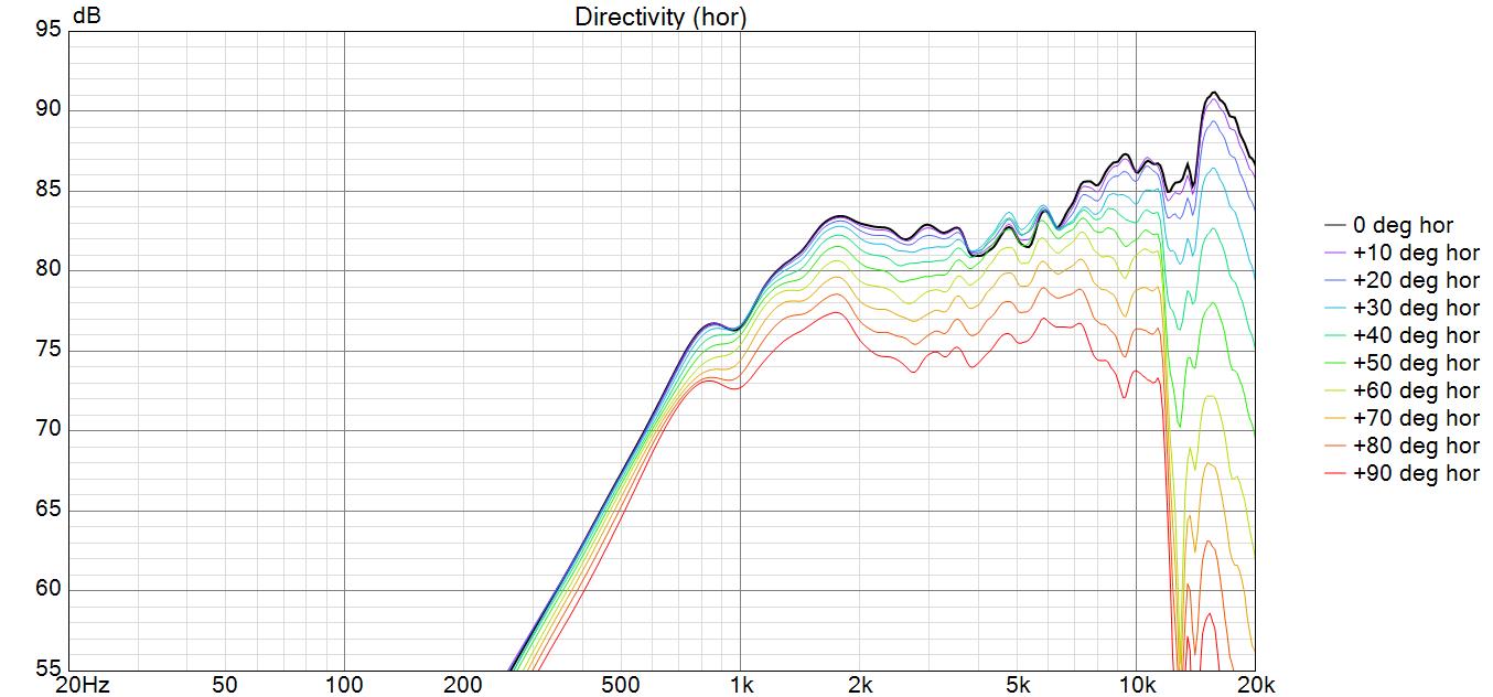
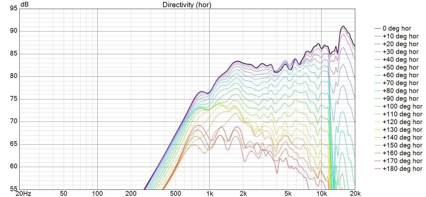
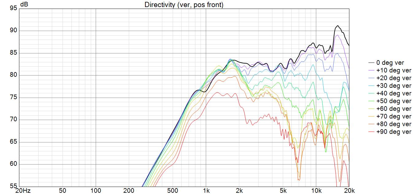
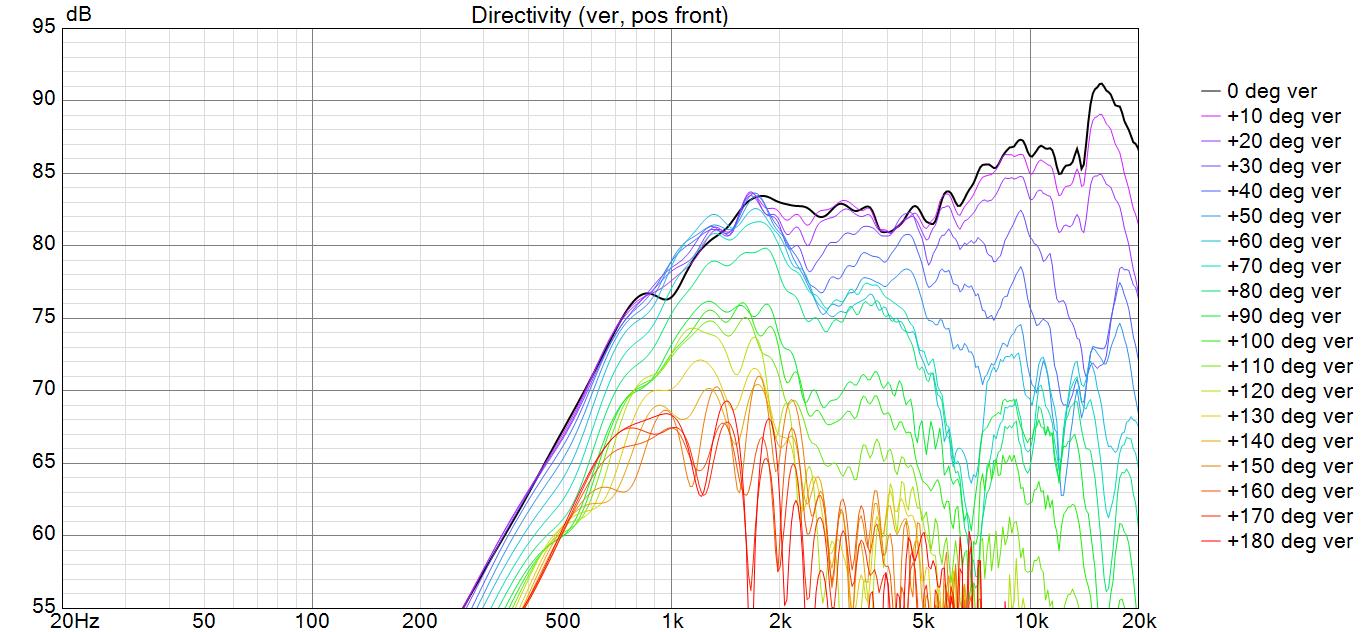
Before I post the PT2522 graphs, let me make a few comments to avoid confusion:
- All measurements were made 1 meter on tweeter axis.
- Overall baffle size was 6.5" by 42.5" with 3/8" radius roundovers. This baffle shape will affect both the measured baffle step AND high frequency diffraction ripple. Do not compare these measurements to the mfg spec sheet curves, which were made on a different baffle.
- My graphs are exported at a 25dB/decade aspect ratio. This is substantially different from the mfg spec sheet aspect ratio.
- These are the PT2522 units that came without back cup, not the PT2522C versions sold with back cup. However, my custom sealed rear chamber looks about the same size as the back cup used on the PT2522C units.
Here are the graphs. I also included a zip file of the Frd’s, so you can load the files into VCAD and play around with the power response and directivity curves.
PT2522 measurements.zip (172.2 KB)
Here is my graph, its the full crossover, the response is different. Edit: here is my Tweeter FRD file with back cup. I did do up to 30 degree measurements and I got the same results.
tweeter.zma (11.3 KB)
tweeter.frd (15.1 KB)
1 Like
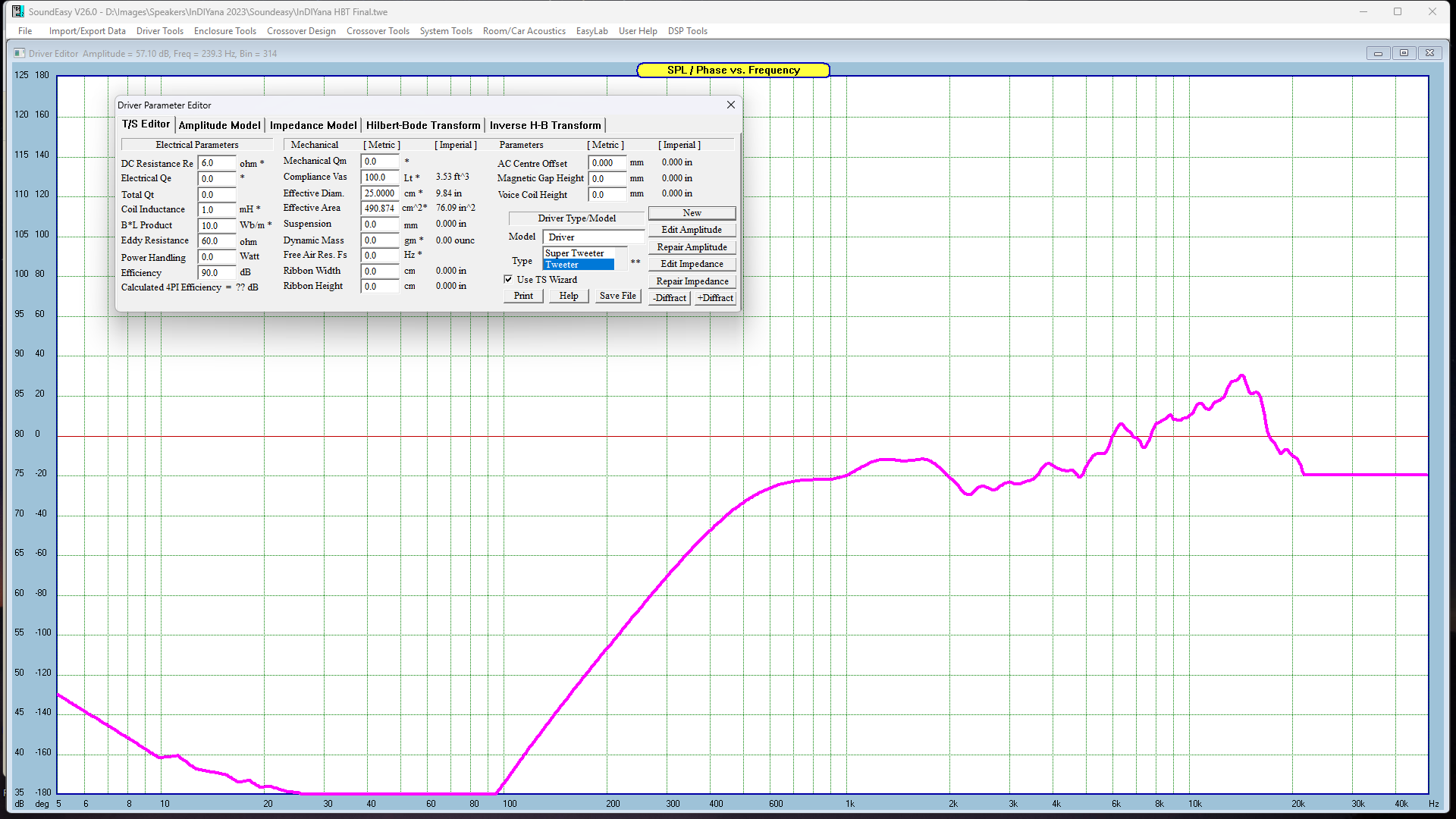
This is the open back version with a large rear enclosure. The rear enclosure is big enough that the response is the same as the response I got without a rear enclosure measured on a test baffle. It looks very similar to the closed back version but goes lower.
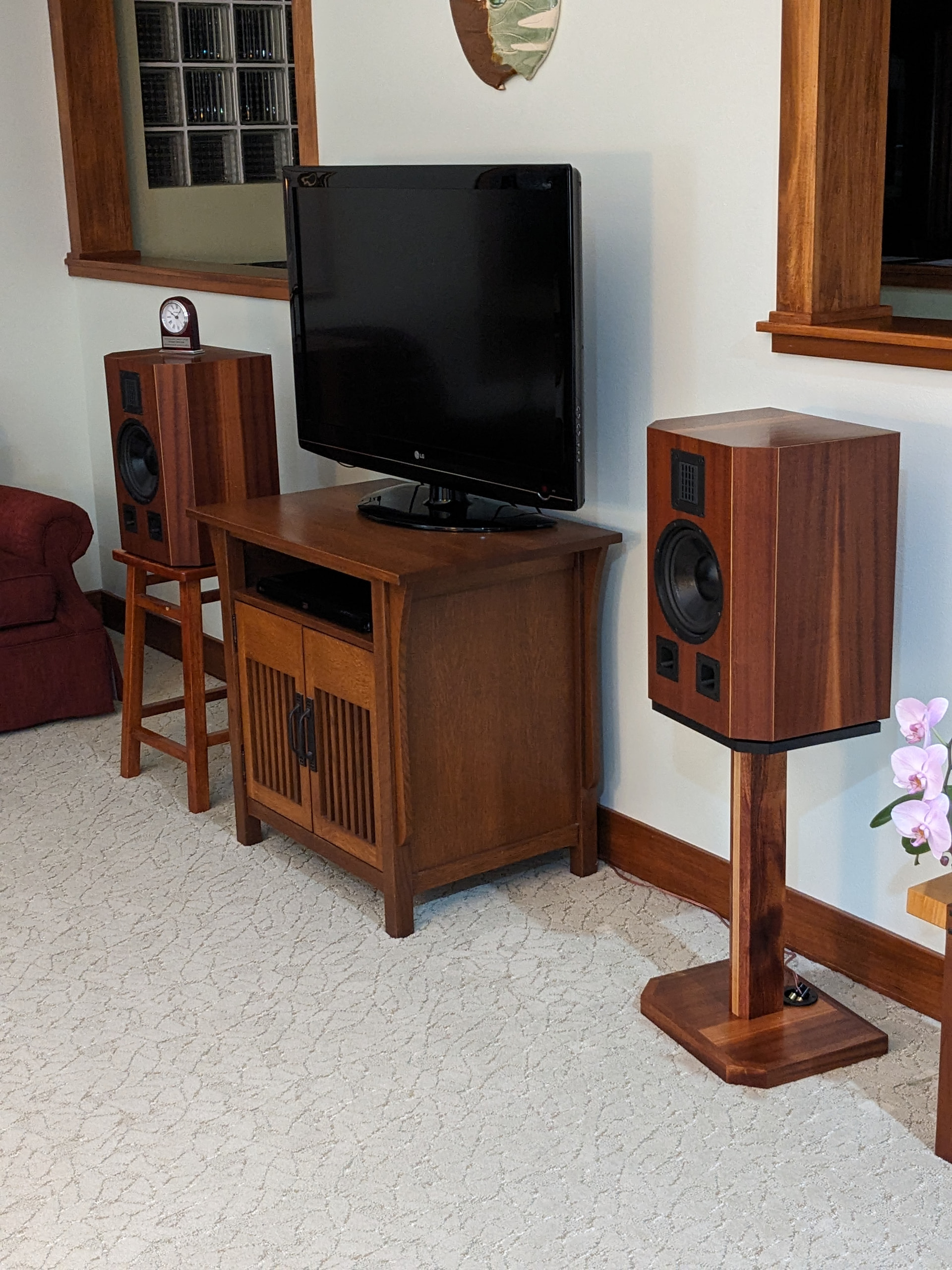
This is the FR in the cabinet below.
2 Likes
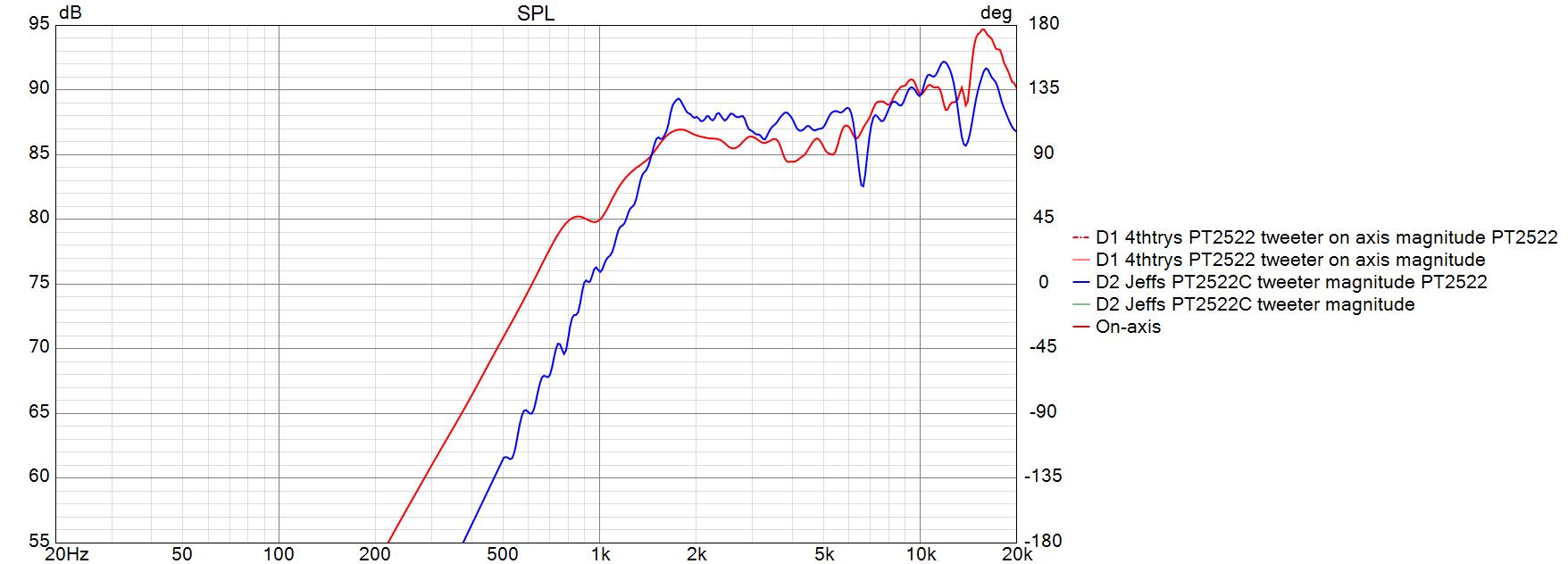
Here is an overlay of Jeff and my on-axis frds for comparison, exported at 25dB/decade. I scaled my measurement by 3.5dB as a guesstimate to account for the difference in our amplifier volume control settings. Jeff’s frd file does not contain data below 500Hz, which accounts for the different roll off rate. My measurements were take full spectrum with no protection capacitor in series with the tweeter. Given the differences in baffle boards, these measurements seem to be in substantial agreement. Others may disagree. Ron’s measurement also appears to be in substantial agreement with my measurements, given the way that baffle shape differences can affect measurements.
1 Like
@Stearns250 , maybe I missed it, but what were your baffle board dimensions and round overs for these measurements?
I believe it was 11” with 1” roundovers. Edit: i just realized I forgot to thank you Bill. So thank you for the comparison its much appreciated.
1 Like
@Stearns250 , I need to correct myself about my comment about the different roll offs of our tweeters. I took my frd file and deleted everything below 500Hz and discovered that this makes very little difference in the shape of my tweeter’s roll off. So the difference in low frequency performance of our two tweeters must be due to the PT2522C version’s back cup being smaller than the custom chamber that I created for my tweeter.
I see that you are using REW to limit the measurement sweep to 500Hz and above, so this looks like a very effective method to protect the tweeter from accidental overload during the measurement process. In the past, I have tried to use OmniMic’s special midrange or tweeter measurements sweeps, but this has not worked for me due to the increase in noise at low frequencies. So if I needed to protect the tweeter, I used a protection cap of about 30 to 50uF in series with the tweeter.
I have a pair of the new GRS true ribbons that I would like to measure. So I am thinking about switching over from Soundeasy to REW to take the measurements, and then limiting the sweep to 500Hz and above like you did here. Or maybe I should limit the sweep to 1kHz and above just to be safe. Don’t want to damage my true ribbon drivers.
@4thtry Not to keep highjacking your build thread, but once upon a time, I did some back cup tests with the PT6818.
https://i.imgur.com/xY8Dh7g.png
https://i.imgur.com/f0rZ6pv.jpg
https://i.imgur.com/WLhnP2J.png
The cyan trace was no rear chamber, and just firing into a 8L enclosure. The other traces are the ones you’d expect.
Anyway, I’ve had thoughts about doing the same for the PT2522-4. I’m not sure Jeff and I could retrofit them into his enclosure. At least, not the way I designed the PT6818 back cups. Maybe I’ll start another thread and get out of your hair. LOL
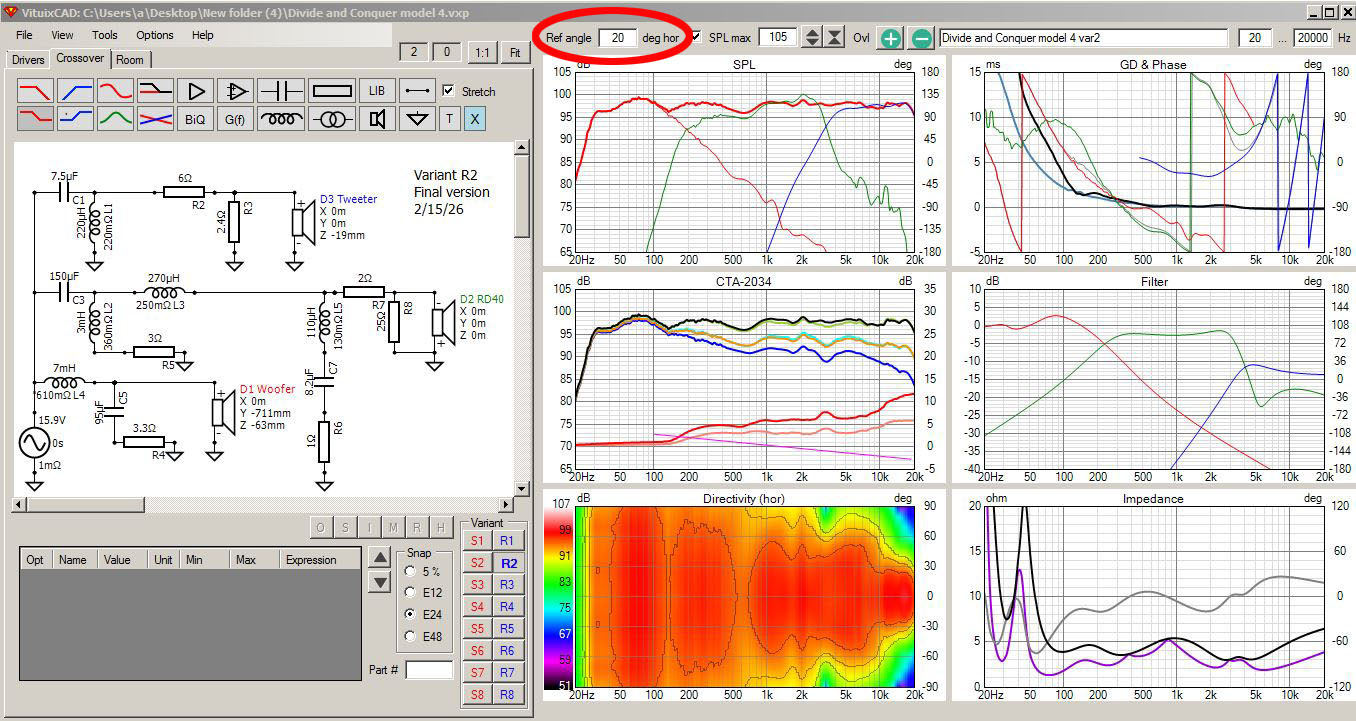
In VCAD, how did you change the design axis to 20 degrees horizontal?
No problem. Keep hi-jacking away. I am enjoying the discussion. Technically, I don’t think you are hi-jacking, as this all relates to how the relative size of my custom back cup affects the shape of the response roll off. Based on your study, it looks like the relative size of the back cup has a significant impact on how the response peaks up and then ultimately rolls off. I initially did not think that this small change in size would make that much of a difference.
1 Like
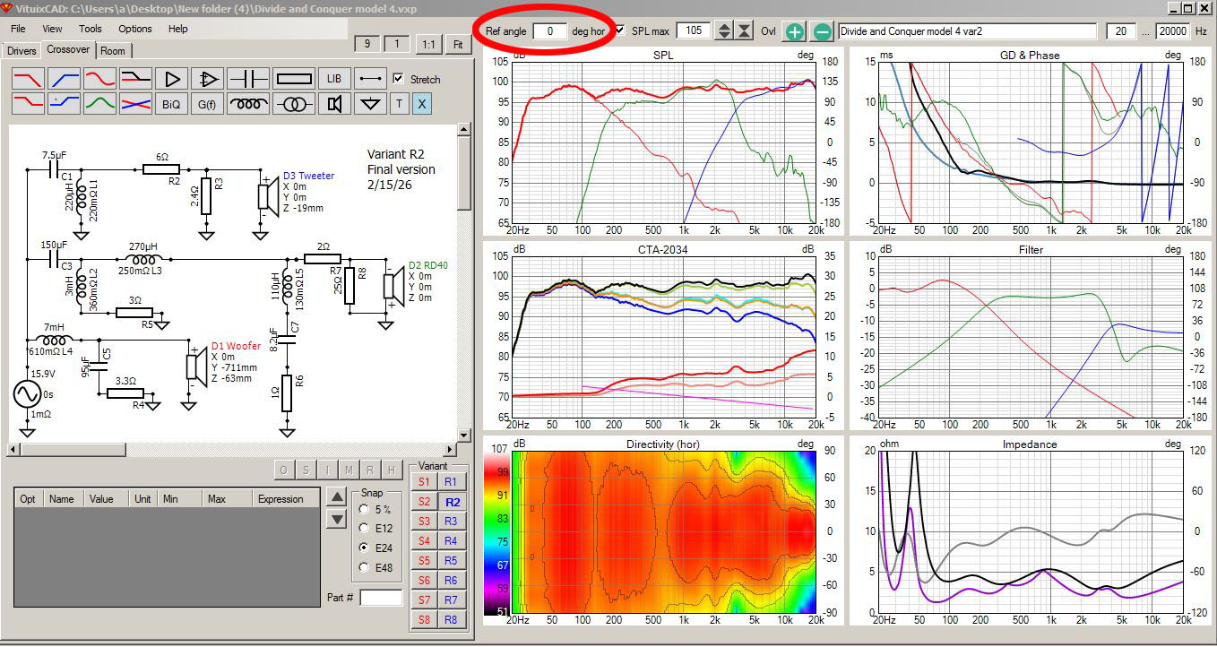
Look at the top of the main window where it says “ref angle”.
2 Likes
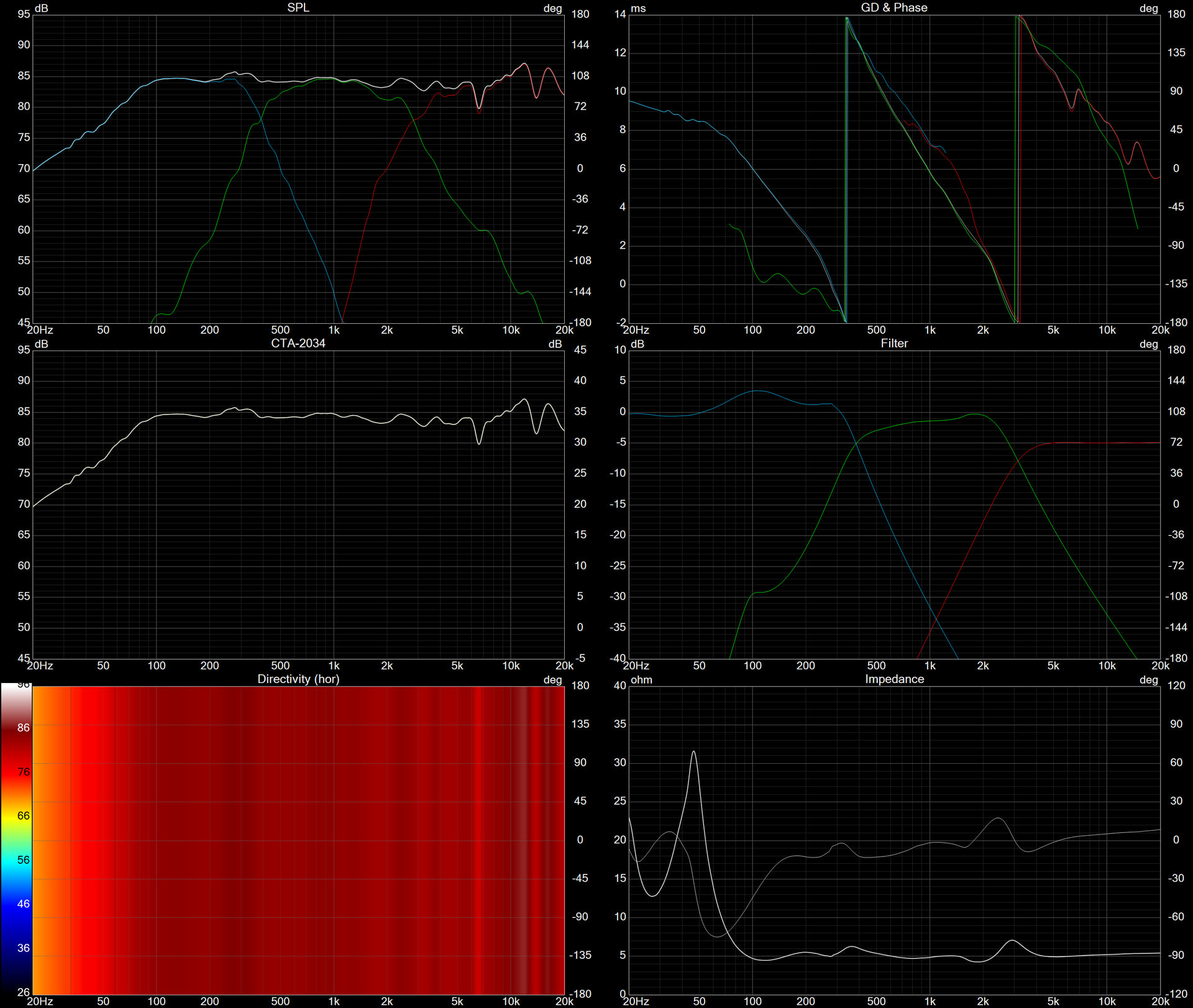
Here are two graphs showing how changing the design axis from 0 degrees to 20 degrees horizontal affects the model. Notice the difference in frequency response verses power response above 10kHz. This tweeter is a little wonky above 10kHz, so I applied some smoothing on the tweeter curves so that I could see the overall trend line a little bit better.
So you will not be toeing them in?
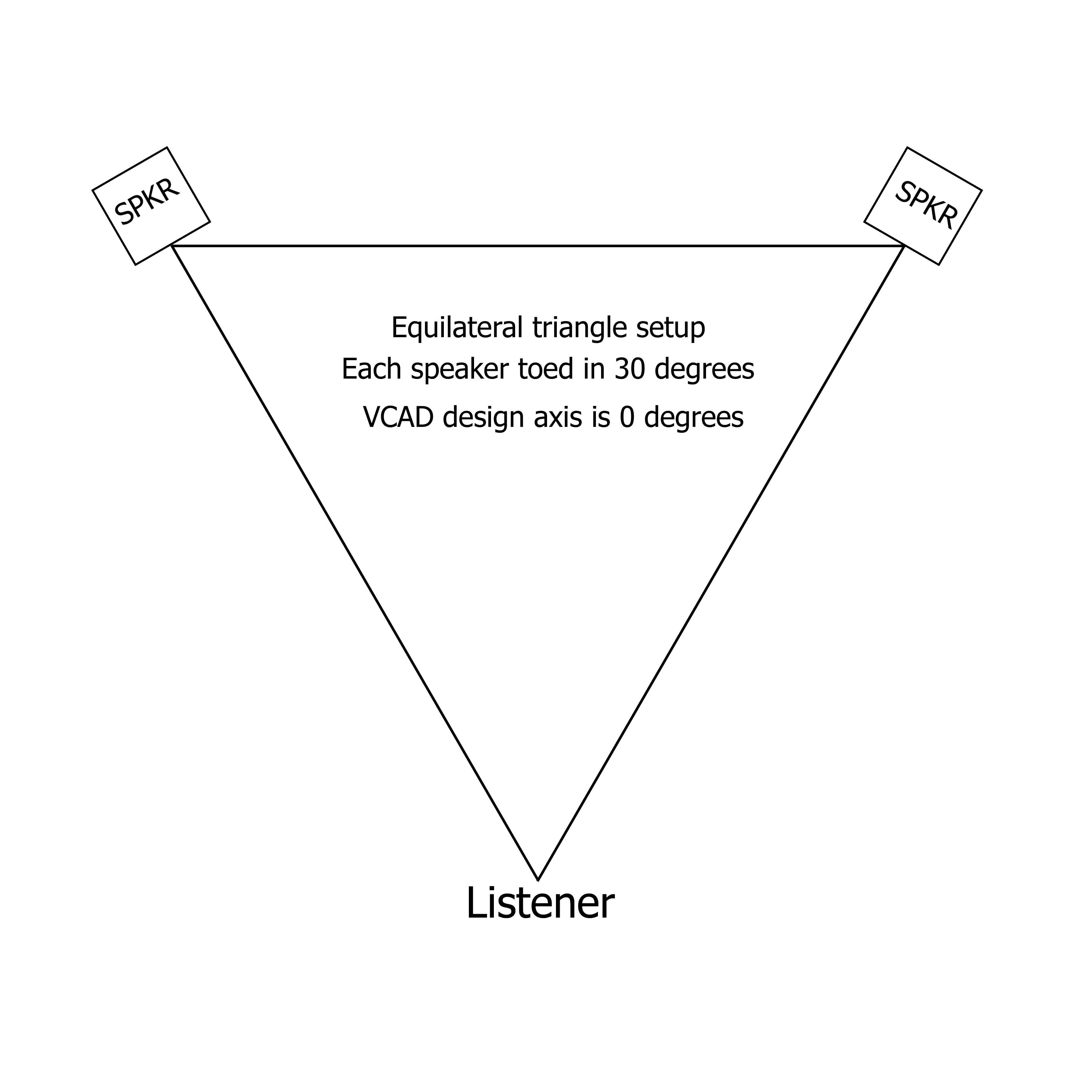
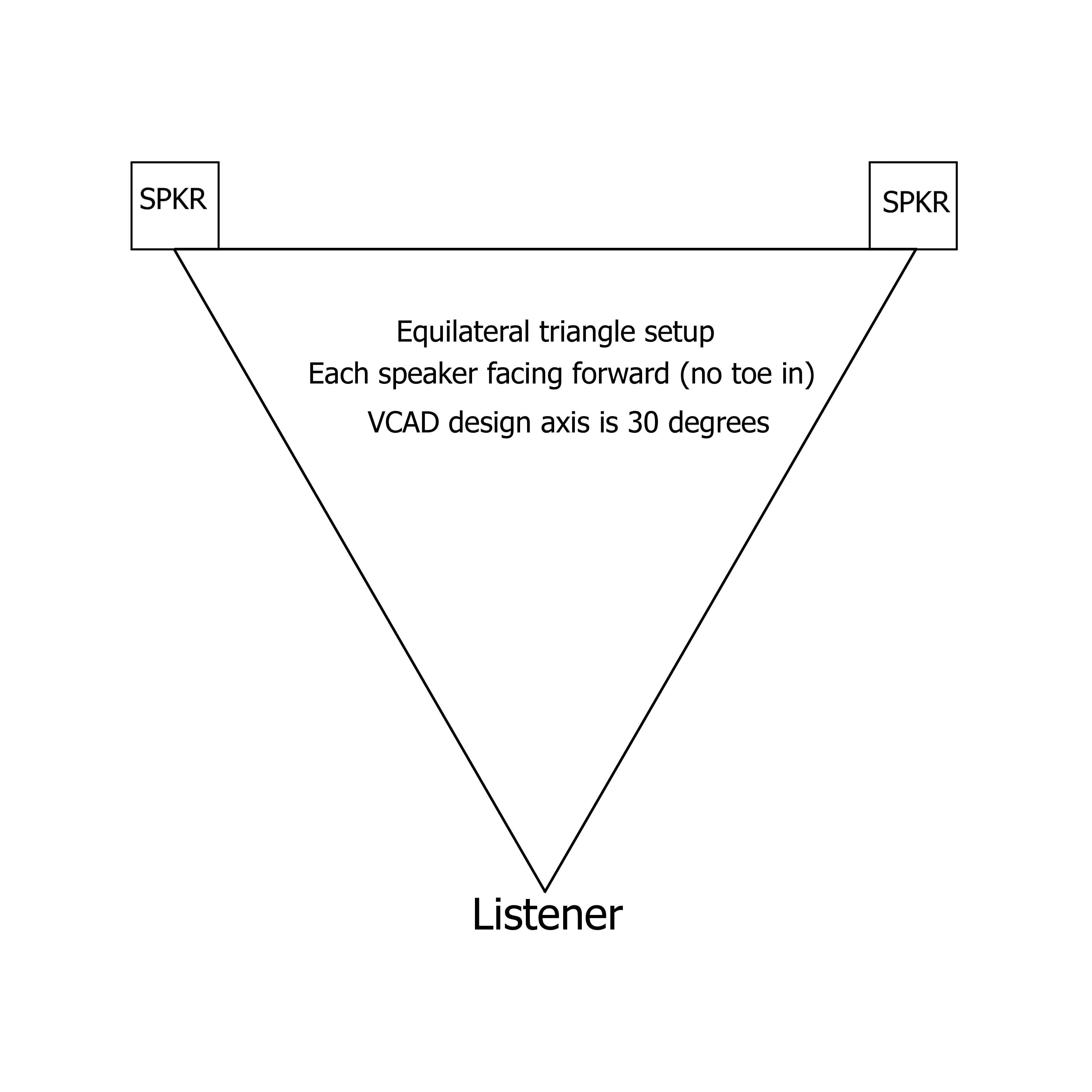
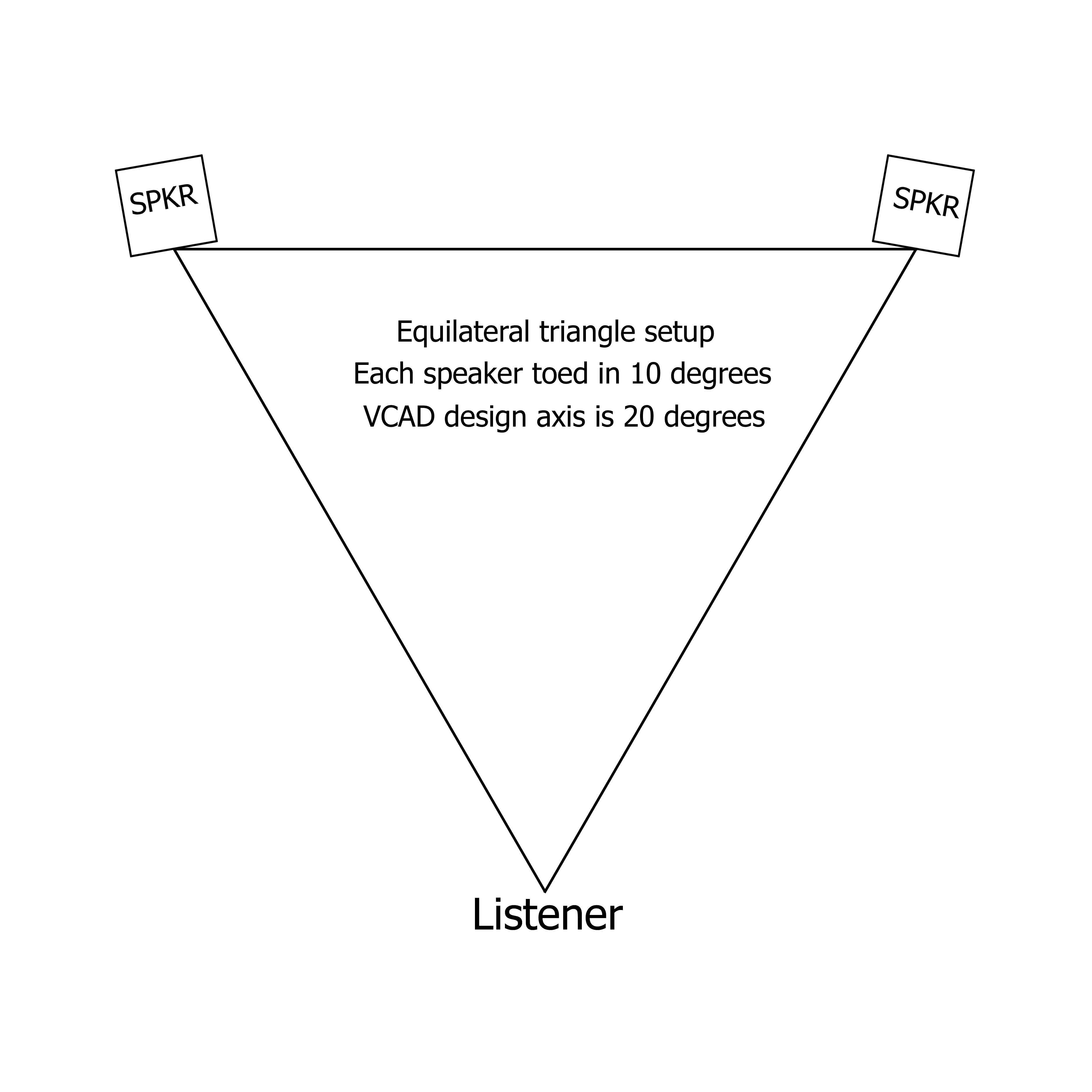
I’ll be toeing each speaker in by 10 degrees, which matches the 20 degree horizontal design axis in the VCAD model. This is assuming an equilateral triangle setup. A full 30 degree toe in would match the 0 degree horizontal design axis in the VCAD model. See my photoshop illustrations below.
2 Likes
To clarify, the 10 degree toe in is what I will be using at home. When I get to Indy, I’ll probably set them up with no toe in. This will put the sweet spot somewhere in the 2nd or 3rd row of seating. When I get to the SDC in August, I’ll probably toe them in about 10 degrees. This will place the center judge in the sweet spot, because the speakers are generally 10 feet apart and the judging table is generally 10 feet back. The left judge would then be about 15 degrees off axis to the left speaker and 25 degrees off axis to the right speaker. And the right judge would be about 25 degrees off axis to the left speaker and 15 degrees off axis to the right speaker.
1 Like
All this talk lately about jumbo sized inductors being used to lower the upper (or single) woofer impedance peak. I didn’t want to be left out, so I modelled a notch using 36mH/300uF/6 ohms. Looking around for cheap inductors, I found a PE buy out sale on 12mH p-cores for $5 each, so I ordered six of them. Connected in series, this will give me two gigantic 36mH inductors with a DCR of only 2.4 ohms. Here is how it changes my model:
Without 36mH notch filter:
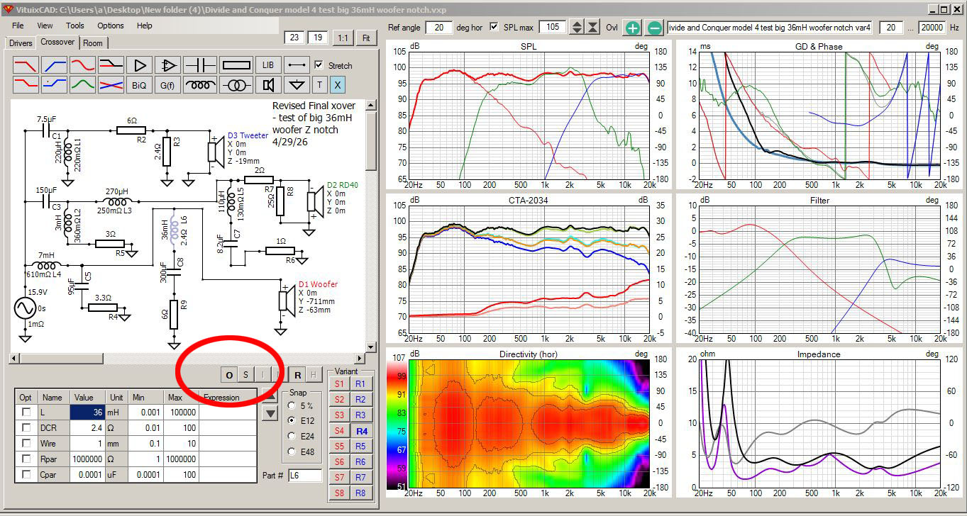
With 36mH notch filter:
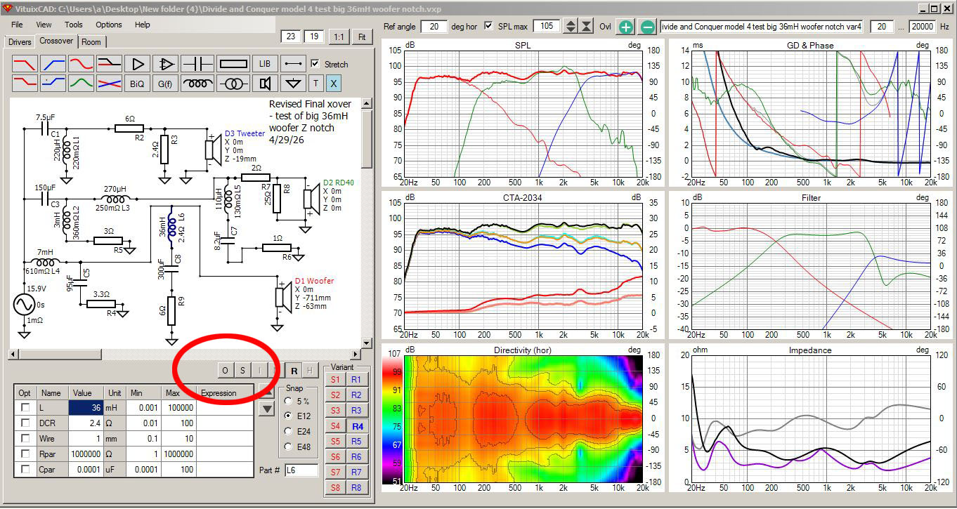
If my reading of the other threads is correct, this should result in tighter bass without the boomy type sound created by the 80Hz bulge. Less strain on the power amplifier as well. When I get and install the inductors next week, I’ll let you know if I can hear a difference.
2 Likes