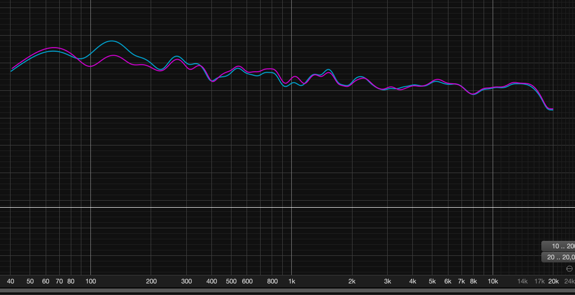
Self pushing 2 7” woofers low xover humping where ended up with a 9mH-100uf-5.6ohm series (shunt) notch, sounds much better with for me though still my overall build think I’m finally done, or enough to fit within challenge params for now. Quick measure of my with (purple) and without (cyan) - port output not merged in this response
1 Like
Ya, your 130Hz hump verses my 80Hz hump makes a huge difference in the value of inductor! My speaker currently sounds a little boomy in the 80Hz region, so hopefully this will help.
It will and it does. Neat little trick to have in the book of xover sorcery. Just be careful of wattage through the resistor.
Good tip! I see you are using two 4 ohm 50W resistors in series, mounted on an aluminum heat sink, on your build. That should definitely do the trick!
Next week, when I get my notch filter parts, I’ll be sure to run wires out the ports and test my notch filter externally using music with heavy bass tracks. I’ll check to see just how hot the resistor is getting when playing music at moderate to loud levels. I’ll also fine tune the resistor value to get just the right amount of bass boost at 80Hz. Modelling is one thing, but listening will be the final judge.
2 Likes
One member had some issues with saturation occurring at relatively low power using those P-Core buyout coils. That was in direct path of driver, though. In a shunt might not matter much.
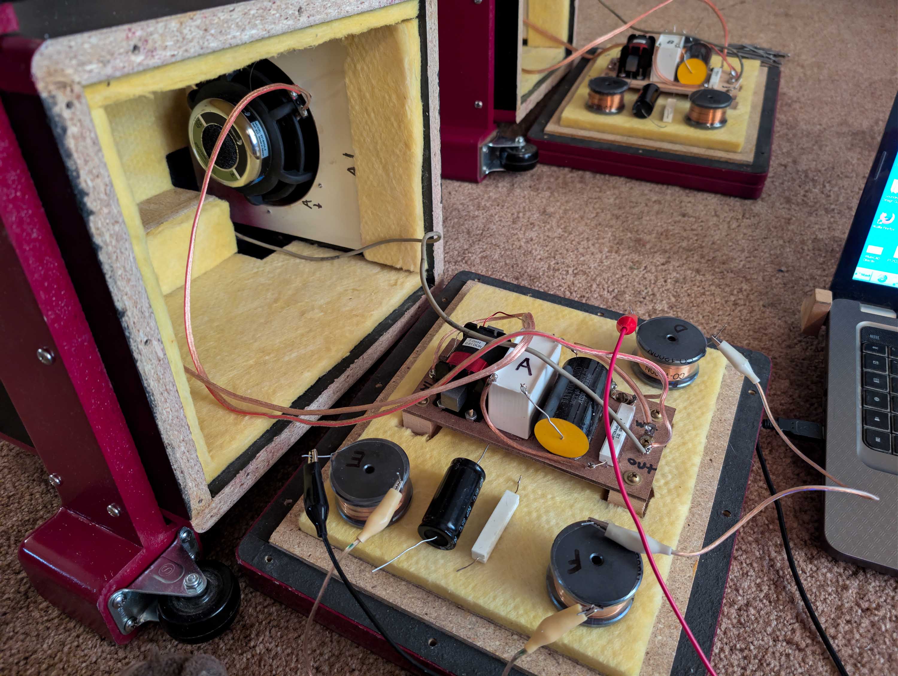
I’m all set up to do an A/B comparison with wires coming out the two ports. The 12mH p-cores are scheduled to arrive on Monday, so when they get here I can quickly clip them in circuit and start listening, measuring, and switching back and forth. I’ll start out by using junk box 10W resistors in series with PE buyout 300uF NPE caps in series with the inductors. Everything shunted across the woofer voice coils:
- I’ll switch back and forth to see if I can hear saturation distortion.
- I’ll set up OmniMic and see if I can measure a distortion difference from 50 to 200Hz.
- I’ll test to see how hot the resistor is getting.
- I’ll tweak the value of the resistor to get the amount of bass “just right” to my ears.
Should be a fun experiment.
3 Likes
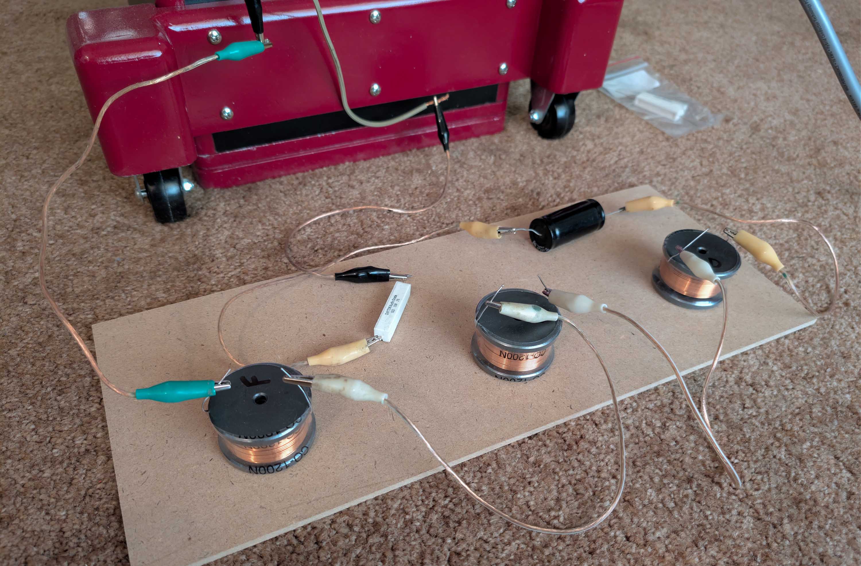
In the above photo, you will notice that I spaced each of the three 12mH inductors about 6 inches apart. This was necessary to keep the value at 36mH. If I move them closer, say 1 inch apart each, the value drops to about 32mH. If I set them right next to each other, the value drops to about 30mH. Turning the center inductor 90 degrees has an interesting effect, boosting the total inductance to 41mH with the three inductors sitting next to each other. But with the center inductor turned 90 degrees, I only have to space each of the three inductors by about 3 inches to reach my target value ot 36mH. Interesting how the magnetic fields couple together at various angles.
2 Likes
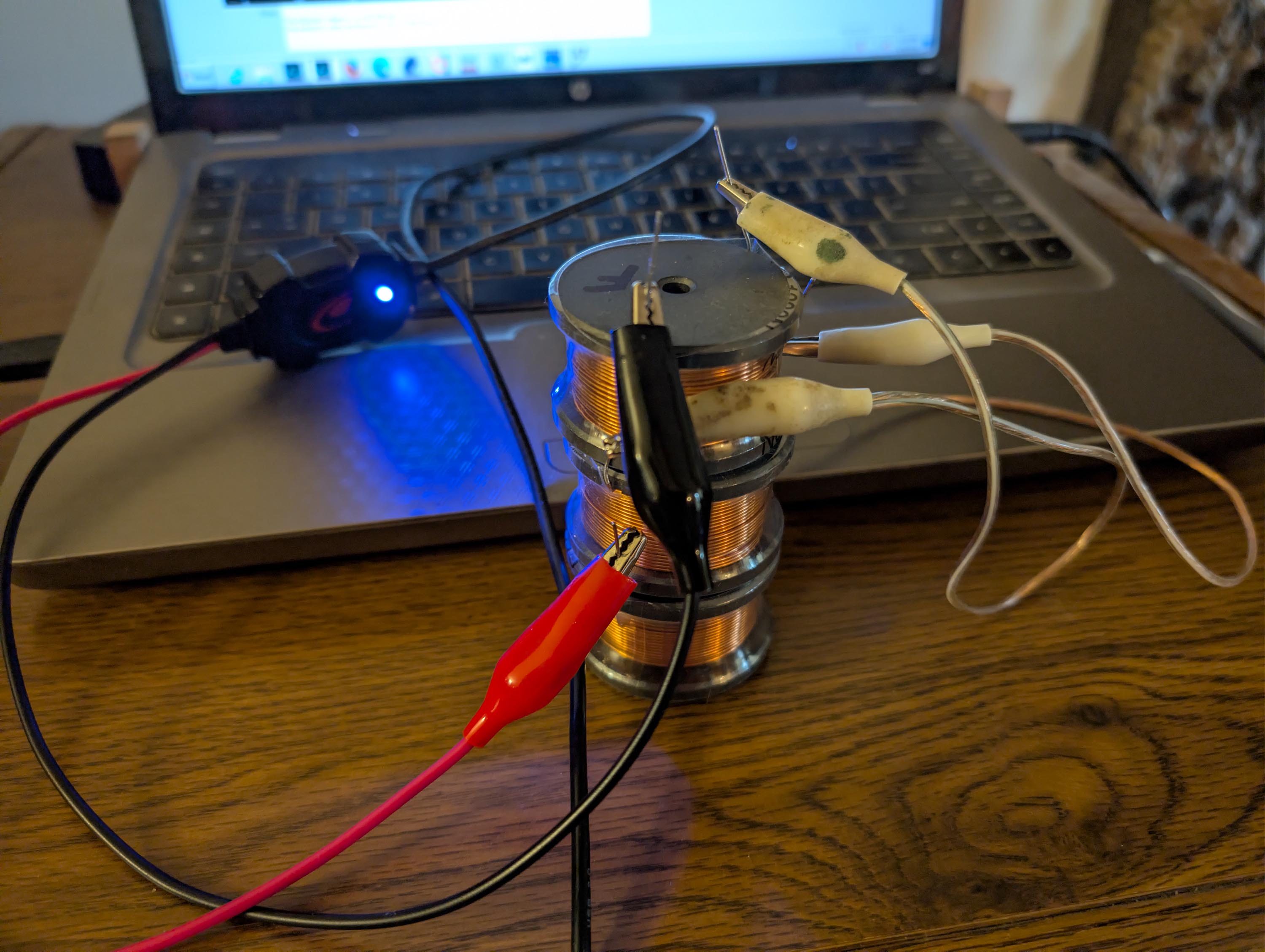
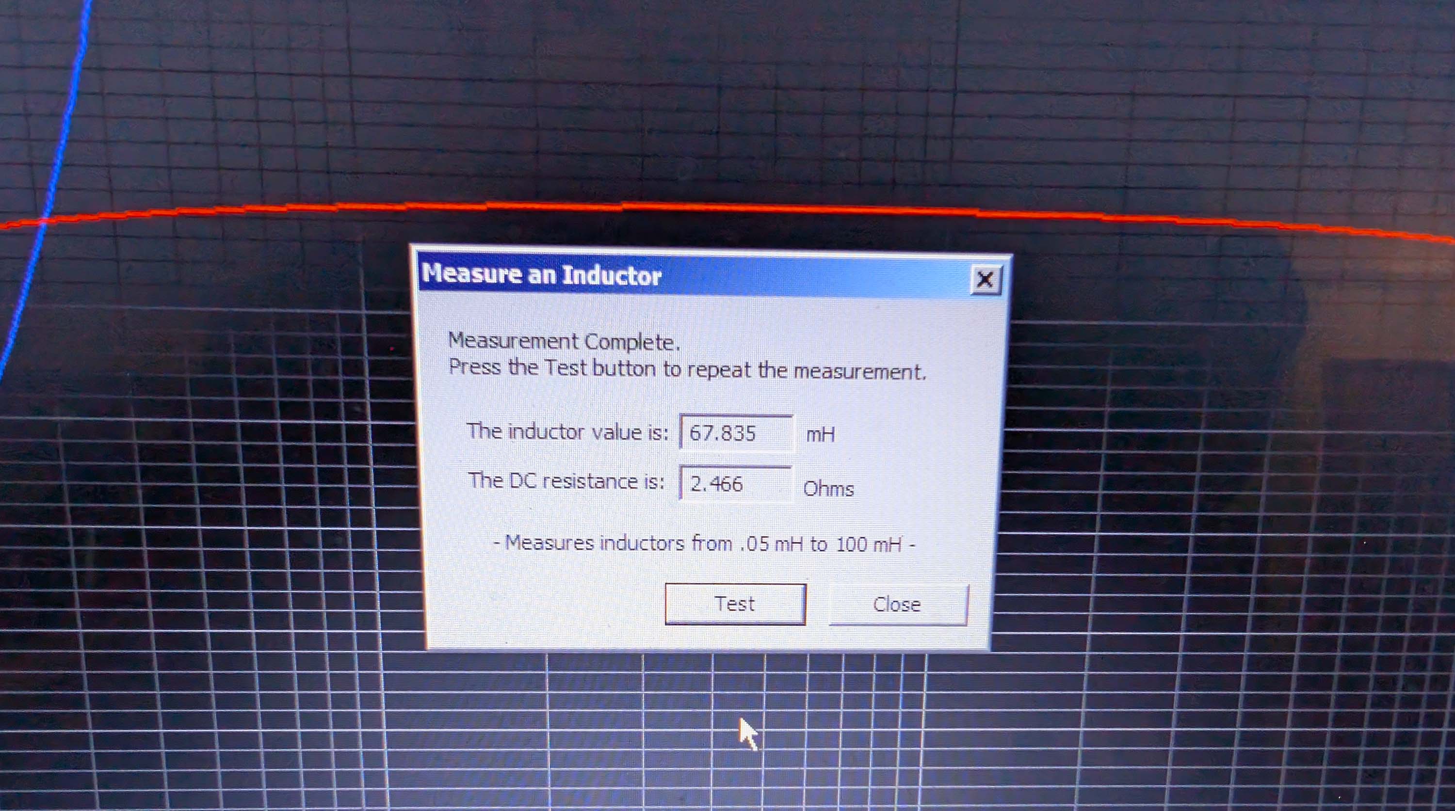
I also tried stacking the three inductors, one on top of each other. Same series connection used. This boosted the total inductance from 36mH all the way up to 67mH! Can you believe that?
3 Likes
Good info, Bill. Keep it coming.
2 Likes
What does 2 stacked get you?
I didn’t write it down, but as I recall, I think the two stack (with one inductor off to the side, but also connected in series), measured 47mH.
I wondered if you could get by with just 2 instead of 3.
I just measured just two inductors stacked (third inductor disconnected). The pair measured 34.8mH with 1.6 ohm DCR. So yes, two stacked would probably work. There has to be some type of price to pay, however. I wonder if two stacked could handle as much power before saturation?
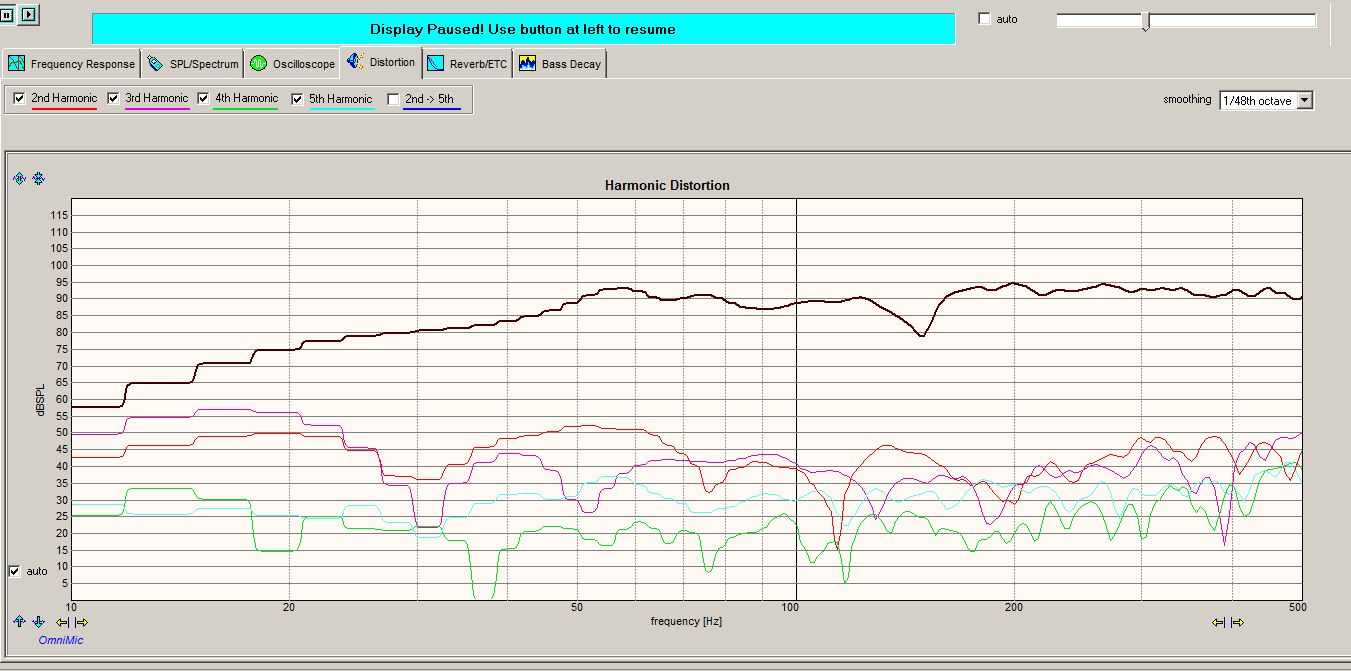
I ran harmonic distortion tests, with and without the woofer notch filter.
With 36mH/300uF/10 ohm notch filter:
Without 36mH/300uF/10 ohm notch filter:
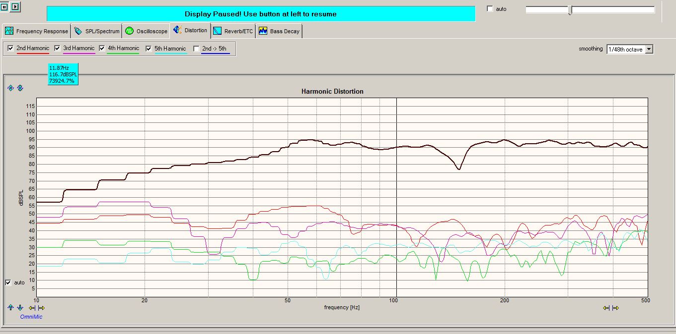
My conclusions, so far:
- The notch filter actually reduces harmonic distortion slightly in the 50 to 300Hz region.
- Using a 6 ohm resistor reduced the 80Hz bulge a little too much, making the speaker sound somewhat thin and anemic. A 10 ohm resistor sounded about right, cutting the bulge by about 2dB or so. It still sounds punchy in the 50 to 100Hz region, but not boomy. Just the way I like it. The HD graph above is with the 10 ohm resistor installed.
- The 150Hz dip on the graphs is the microphone tip to woofer to floor measurement bounce. Ignore it.
- After playing moderately loud music for about 30 minutes or so, the 10 ohm, 10W resistor got warm to the touch, but not hot. I think it will be OK.
- After playing moderately loud music for about 30 minutes or so, my 100wpc amplifier heat sinks were very hot (cooking). This is not an easy amplifier load.
2 Likes
Right on, good info.
2 Likes
Testing the layout. This inductor arrangement gives me the 35.77mH total. That should be fine. The 12mH p-core on the left front is about 3.5" away from the 7mH iron core, but I think this should be OK because the windings are turned 90 degrees and oriented toward the end of the iron core laminations. Please double check and correct me if I am wrong.
2 Likes
Holy big inductor Batman!
1 Like
That was me, many moons ago. It was one of the 3.5 mH coils on a Dayton RS-180 I believe. They do seem to work OK as a shunt.