Pretty sure @Eggguy is asking how you glue the raw particle board edge to the melamine surface when gluing your panels together ![]()
1 Like
Without knowing specifically how it is being done here, Titebong makes a specific glue for glueing to a melamine surface. Also another brand, Roo Glue comes to mind.
OK, I think I get it now. I misread because I did not actually glue the melamine to the raw particle board edges. I cut dados along all glue surface edges (see post #95 above), so I was gluing particle board to particle board.
On previous builds, I didn’t have my dedicated dado blade table saw set up yet, so I made simple butt joints by gluing particle board edges to melamine. But I always roughed up the melamine surface with 60 grit sandpaper beforehand to get a better bond. But this never seemed like a good solution; hence my conversion over to dado type joinery. I use Tite Bond II for all the joints.
1 Like
When I install the ports later on, however, I will need to glue the particle board to the melamine coating. That must be what @Eggguy was asking about. I should have cut dados for the ports as well, but I didn’t. So after I trim the ports to length with measurements, I will need to glue them permanently in place with either Tite Bond II or 100% silicone sealant.
After much thought and consideration, decided to rename my speaker “Divide and Conquer” as suggested by @DrewsBrews Thanks, Drew! Seems to be a better fit to the overall concept. RD40’s divided in two to conquer directivity!
Split Personality would work too, but I think that this name implies that the speaker would have a different sound on different days or in different rooms. ![]() Since the goal is to get the speaker to sound roughly the same in different sized rooms or on different days, I think Divide and Conquer is the better choice.
Since the goal is to get the speaker to sound roughly the same in different sized rooms or on different days, I think Divide and Conquer is the better choice.
3 Likes
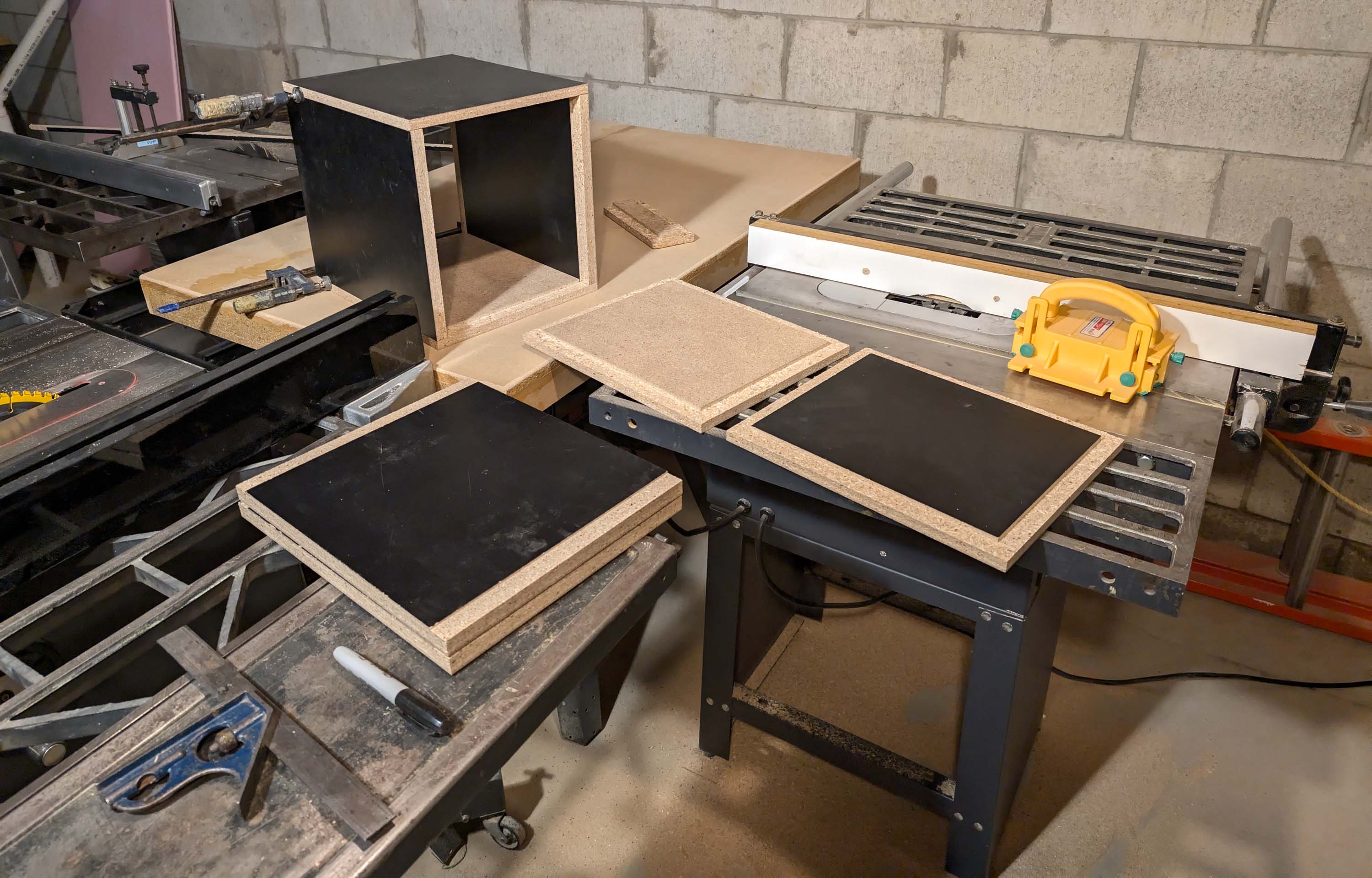
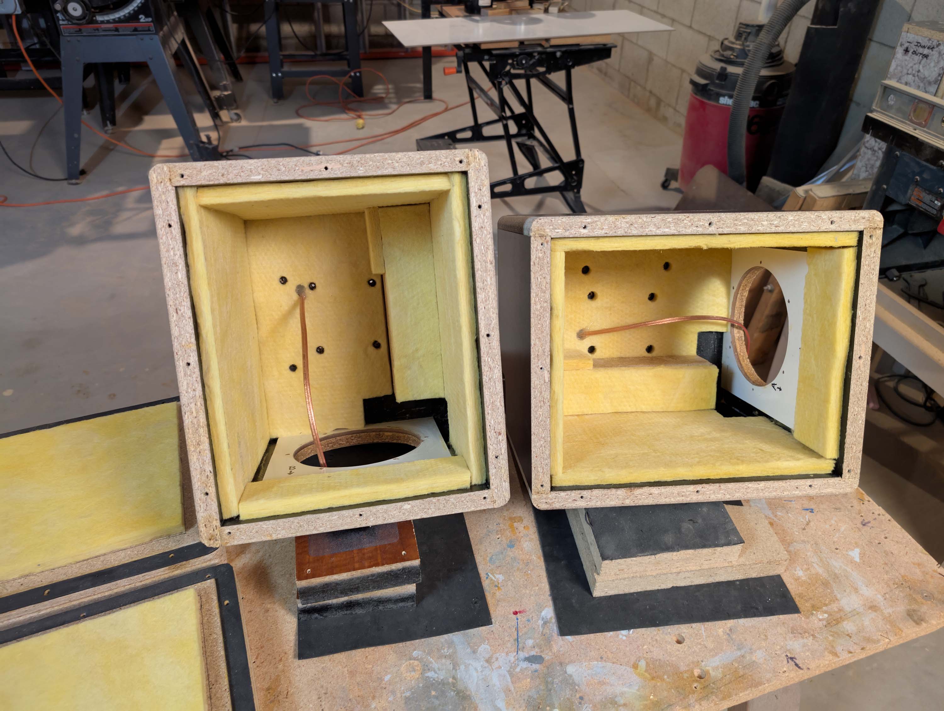
Bass bin progress report:
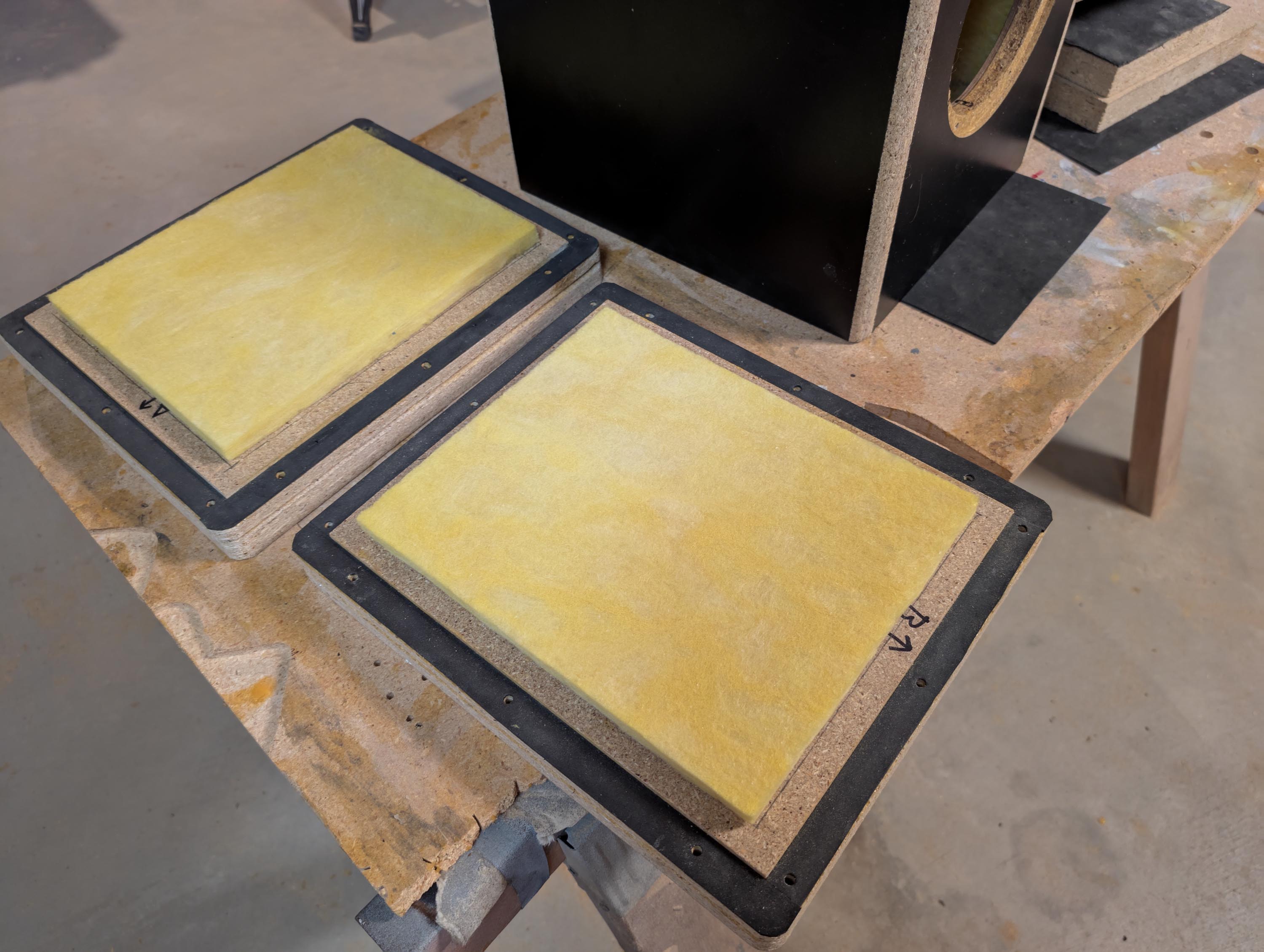
1/2" fiberglass from Menards:
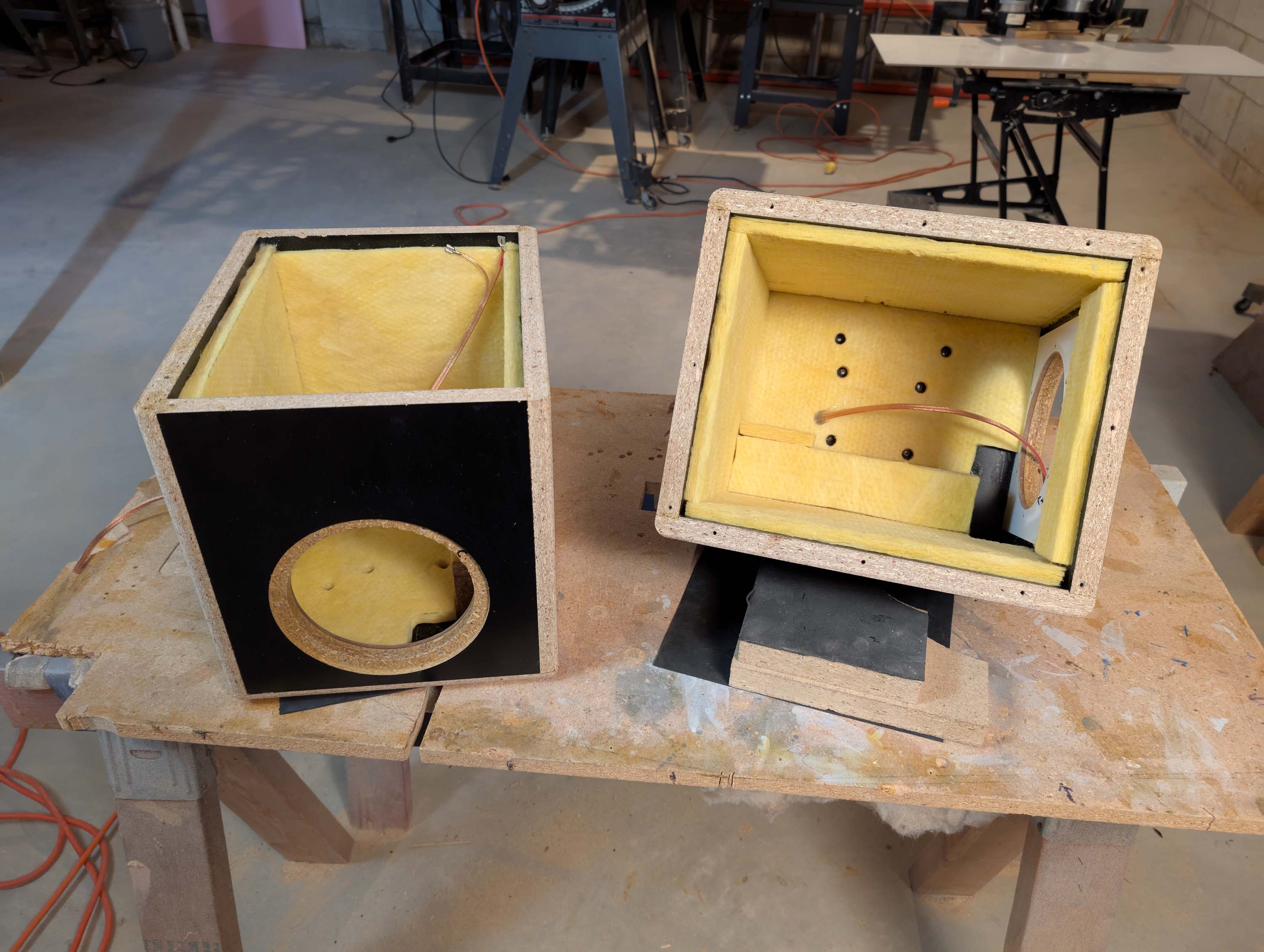
Removable bottom panels done:
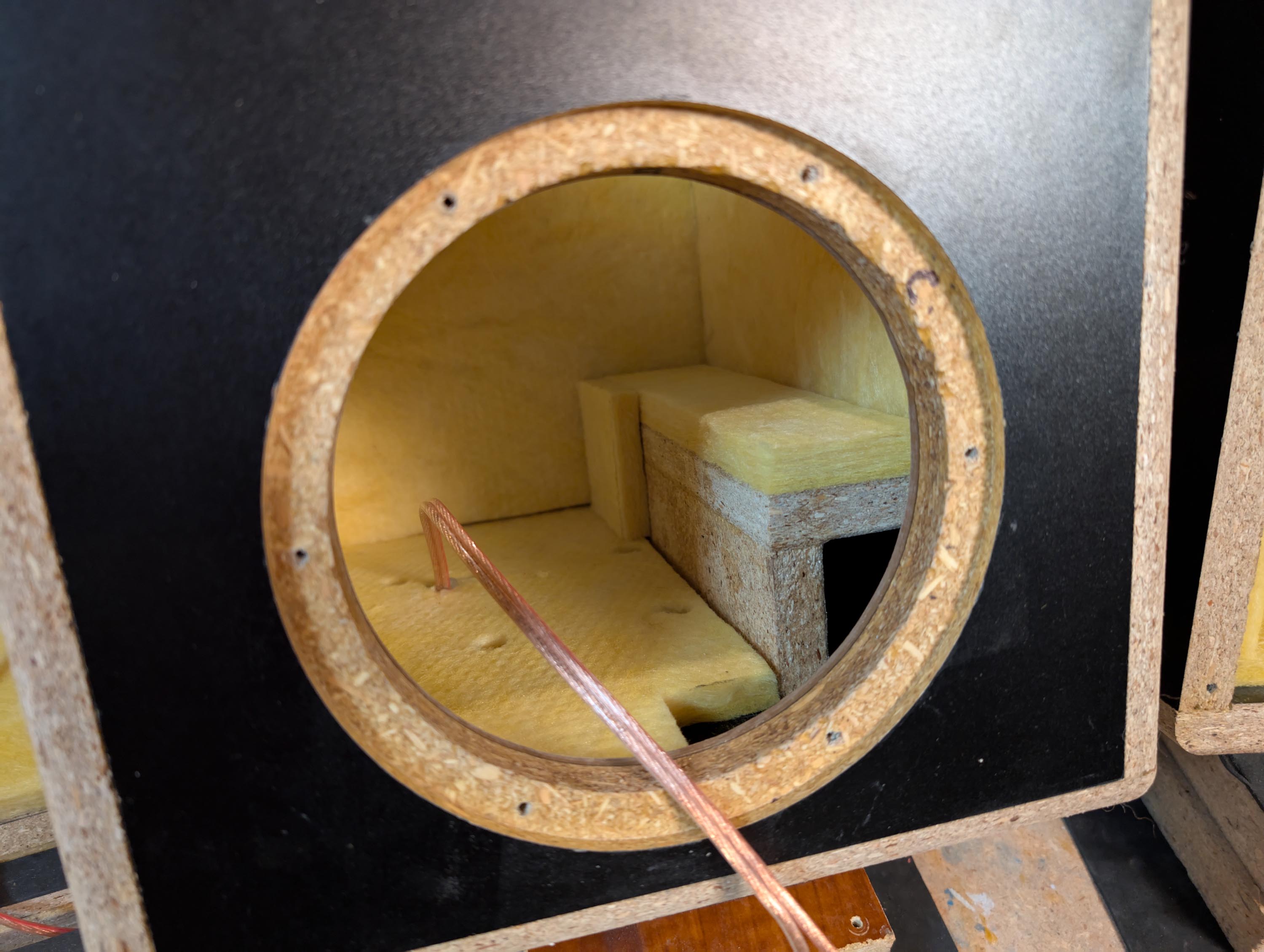
Ports done:
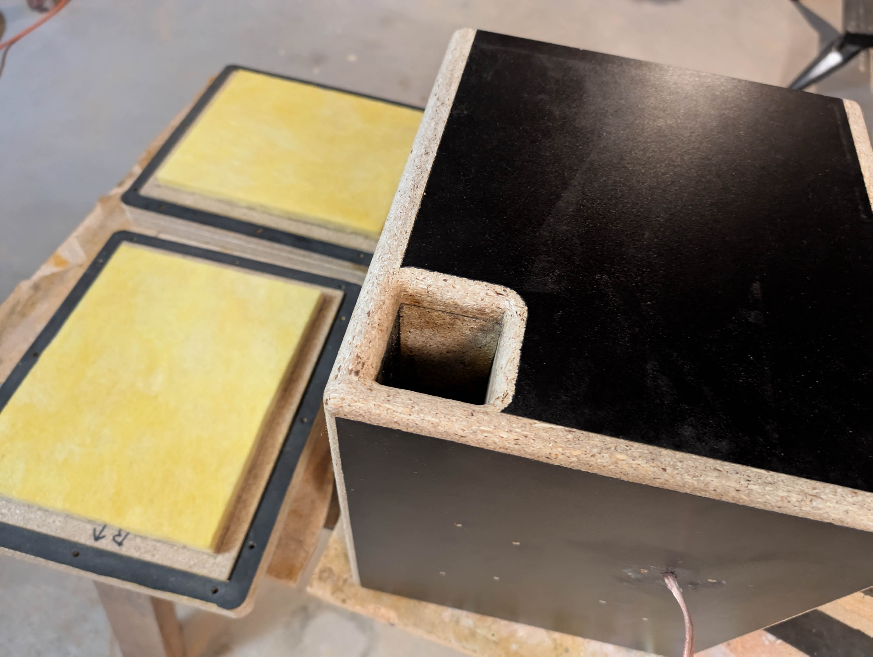
Holes in fiberglass for screws and wires sealed with 100% silicone(check):
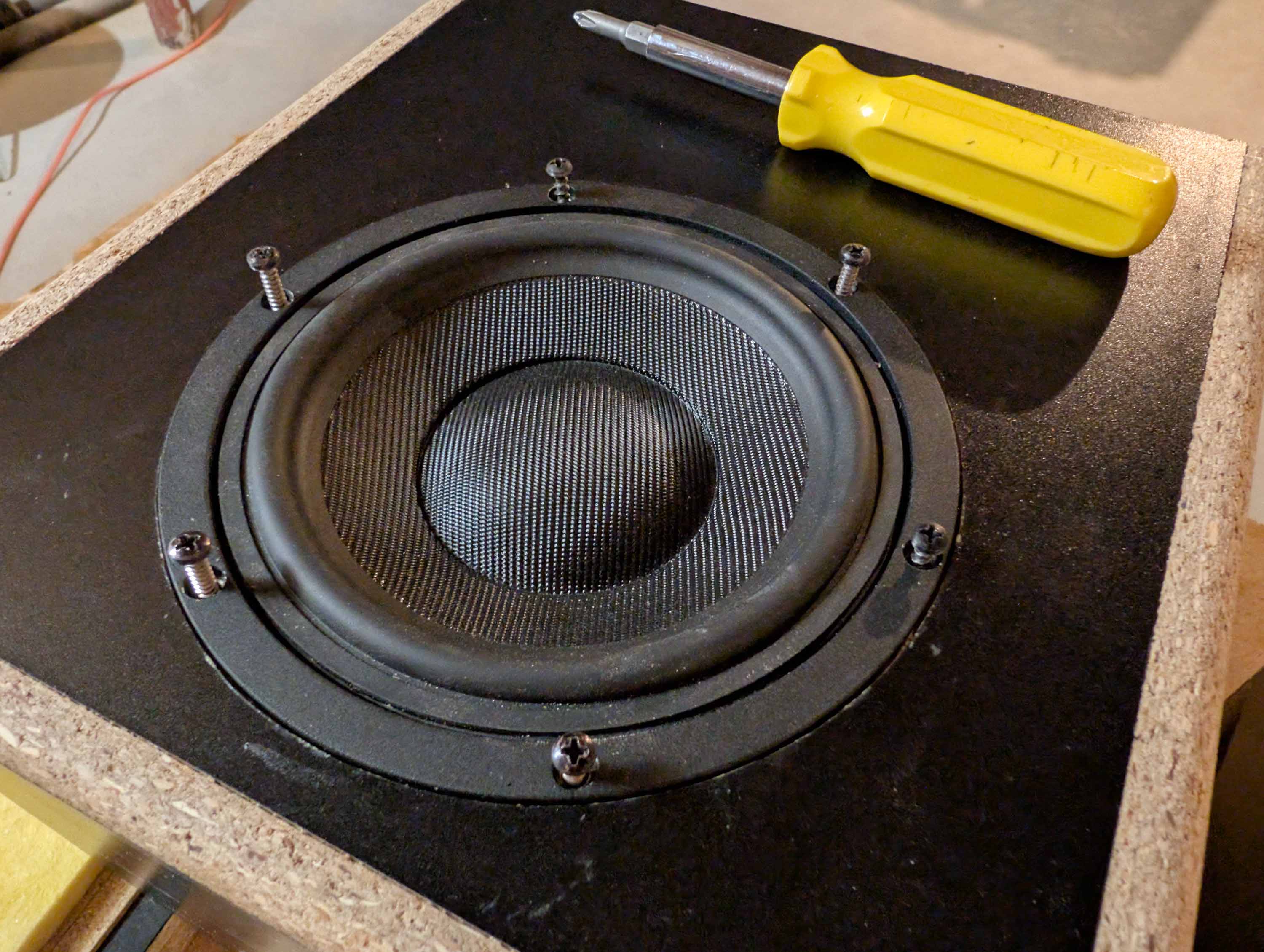
Mounting driver:
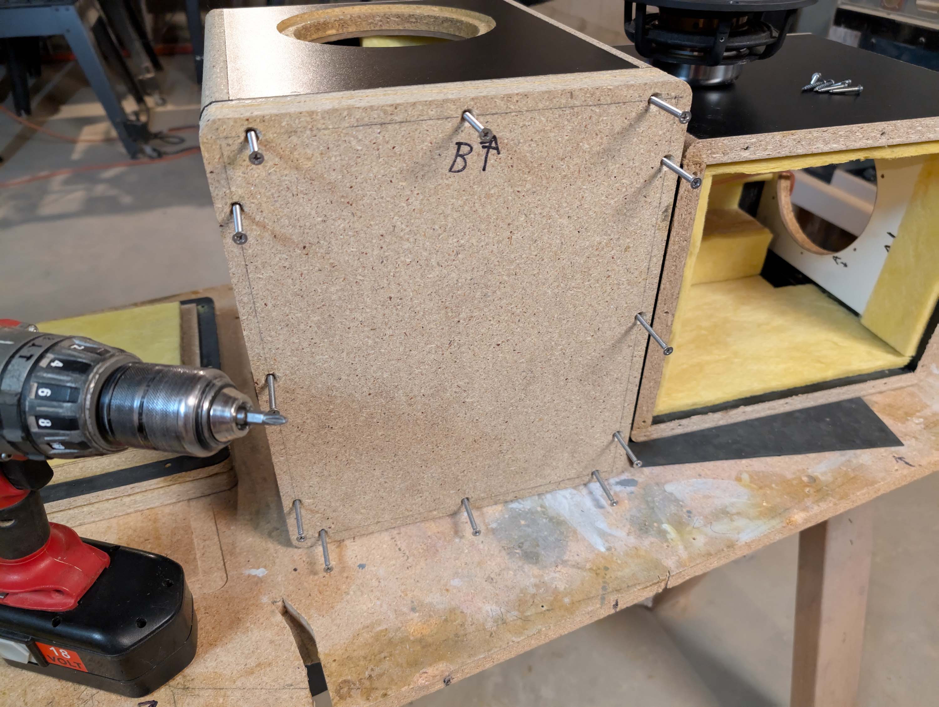
Mounting 1.5" thick bottom panel with twelve 3" long screws:
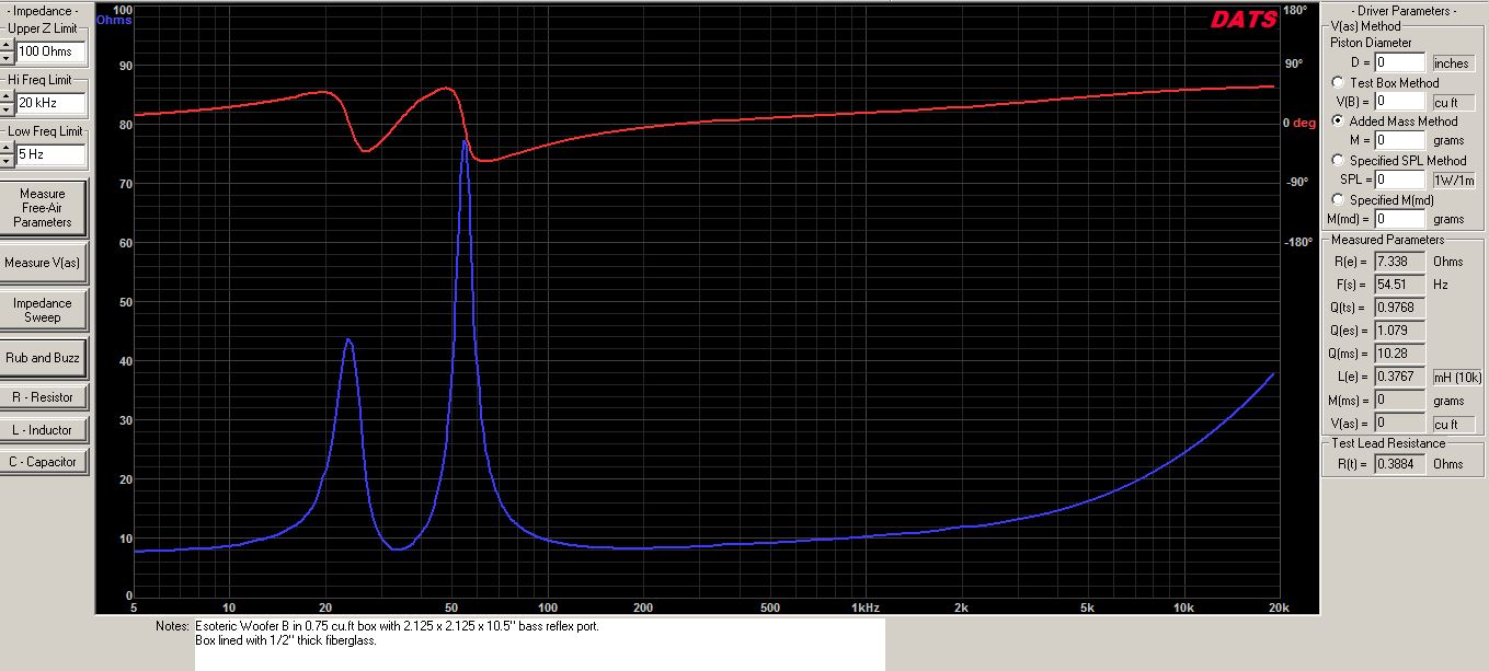
Impedance curve, no xover:
VCAD diffraction model:

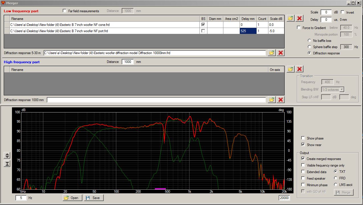
VCAD cone+port+diffraction model merger screen:
3 Likes
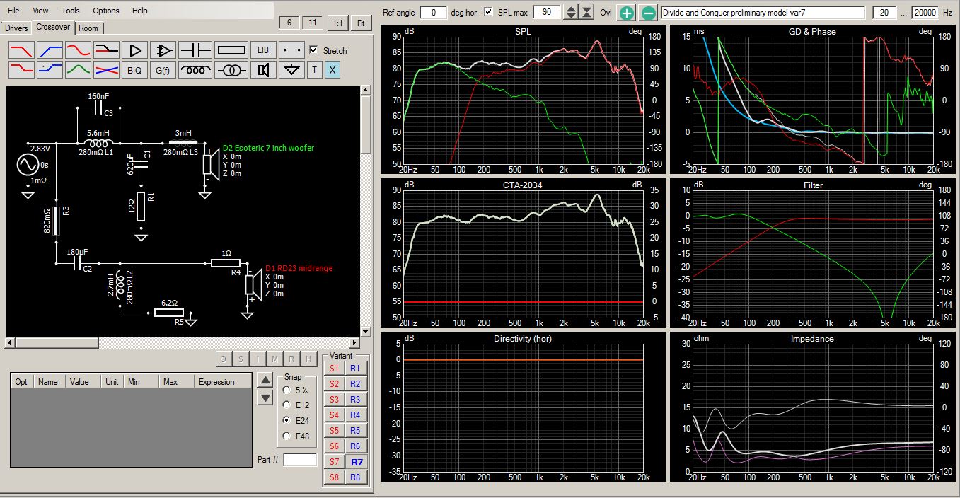
Today I took some quick on-axis measurements to check out the lower crossover point. Too lazy to set up my turntable to take the full spin measurements. Maybe I’ll do that tomorrow. I get a good reverse null at 165Hz. Might strain the RD40’s a little bit with the shallow roll off. Minimum impedance of 4 ohms at 400Hz looks OK. The woofer box has a nasty resonance coming out the port at approx 450Hz, but that small resonance seems to get completely lost in the overall scheme of things. Ignore everything above 1kHz in the graph; that mess will be pounded flat when I take more measurements and add in the tweeter.
1 Like
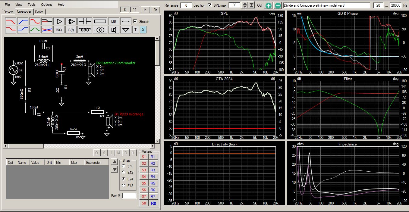
Why the woofer zobel with such high values? It looks like it would drop the impedance around 50-100 Hz range. Im sure you have a good reason for it.
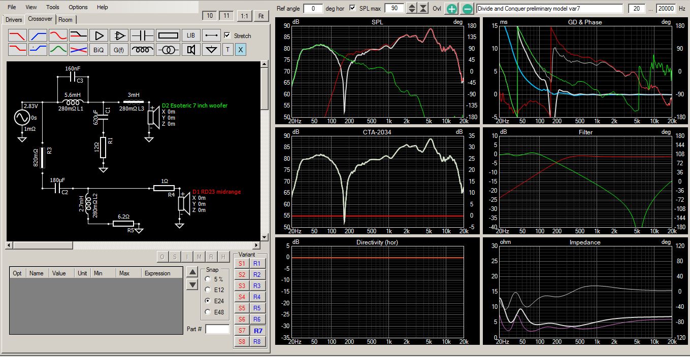
Here is what the model looks like with the woofer “zobel” removed. As you can see, it is actually a combo zobel/bass shaping contour network. It brings down the dual resonance peaks, but it also helps to roll off the woofer a little faster than just using the 5.6mH inductor alone. When I tried to use a standard 2nd order low pass filter in this position, the impedance droped below 2 ohms around 100Hz or so. So I had to look for another solution.
Also, removing the zobel moves the crossover up from 165 to about 200Hz. I want to keep the xover as low as possible because of the 4 octaves rule. 200Hz would push my upper xover to 3200Hz instead of 2500Hz.
So I was right. You do have a good reason.
1 Like
@Ani , I just completed a full set of spin measurements for this project. 180 degree horizontal and vertical spins for all drivers. My measurements on the RD40’s, however, were made with the foam blockers and tweeter in place. Since I am all set up for measurements, would you like me to run up a set of 0 to 90 degree horizontal polars on the RD40’s alone with the tweeter and foam blockers removed? They are very easy to remove for testing. The enclosure measures 6.5" W x 43" tall x 8" deep and is completely sealed and stuffed with Acousta-stuf and one layer of 1.5" convoluted foam.
Hi Bill, if you can do that will be really helpful. I am interested i nthe raw data. unfortunately i am not cuurently setup to measure the RD40 on my own.
My enclusure will more or less mirror yours, so i should be able to use most of the data you are gathering.
Ani, attached is a zip file with the raw FRD data files. 0 to 90 degrees, 1 meter on-axis, in 15 degree increments, using the stock RD40’s without my foam blocker or tweeter modifications. Also included is an impedance zma file of the RD40 mounted in my completely stuffed and sealed cabinet, in case you need that too. Also included is a near field (NF) measurement taken at a mic distance of 1/4," in case you want to experiment with merging the near field and far field curves. Enjoy!
Unmodified RD40 FRDs.zip (531.0 KB)
1 Like
Thanks, Bill. I’ll study it in detail.
Did you get a chance to listen yet?
No listening yet. I still have quite a bit of work to do in VituixCAD before I get to that point (ie., set up diffraction models for mid and woofs, then merge NF/FF/diffraction data for mids and woofs, then pound the squigglies flat on the CAD 6 pack screen, etc.) Probably be at least a week or so before I get to the listening point. Nice thing, though, is that VituixCAD lets me convolute and export my crossover for digital playback. So I can listen before ordering parts.
1 Like
One of the most difficult tasks in creating a complete VCAD model is setting up the diffraction and merger screens. So over the next day or two I will be posting detailed screen captures showing how (and why) I am setting these up for this particular speaker system. I’ve done about 10 or so of these setups on previous builds, so I have the basics down. But I am by no means an expert. Let me know if I make any mistakes along the way.
Thanks Bill I am struggling to make the switch over to Vcad. This will help a lot!
First off, I created a total of six diffraction models to cover the woofers and RD40 midrange drivers. When doing the spin measurements, I took two sets of midrange measurements: one set WITH the foam blockers installed and one set WITHOUT the foam blockers installed. The models that I have labeled RD40 do NOT include the upper and lower foam blockers installed. The models that I have labeled RD23 include the upper and lower foam blockers. I am calling these the RD23’s because they are shorter and have a slightly different diffraction signature. I made these extra measurements because I wanted to see/hear how the foam blockers were changing the overall response and modeling.
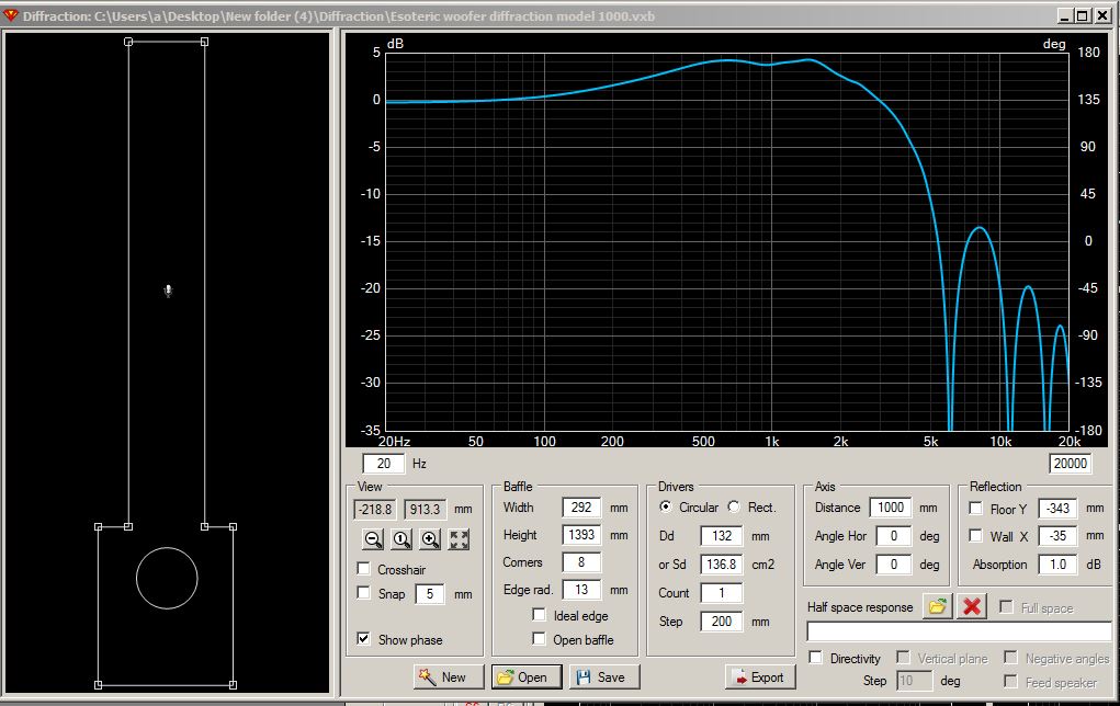
Below: Woofer diffraction model at 1000mm distance. This 1000mm model is needed to make a small correction to the far field (FF) 1 meter woofer measurements:
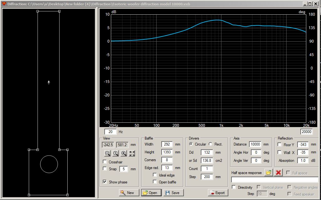
Below: Woofer diffraction model at 10000mm distance. This additional 10000mm model is needed to apply the full 6dB of BSC to the near field (NF) woofer measurements.
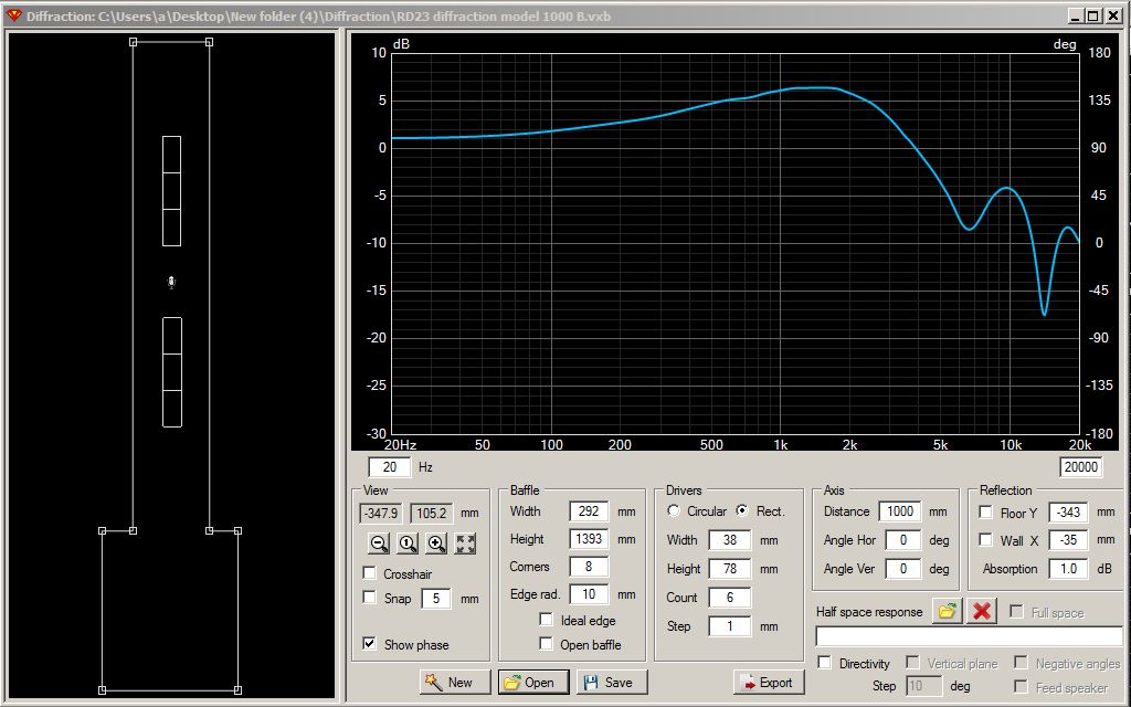
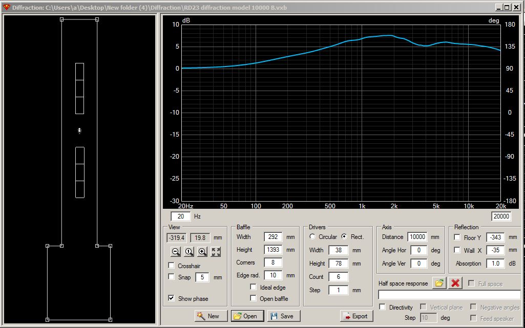
Below: RD23 midrange diffraction model at 1000mm distance:
Below: RD23 midrange diffraction model at 10000mm distance:
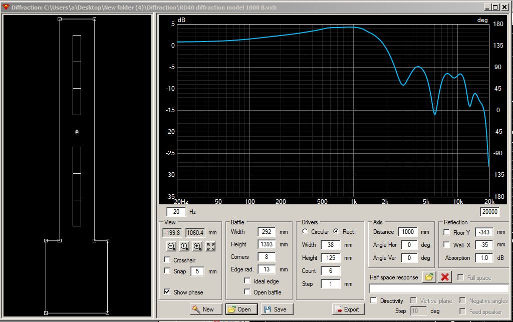
Below: RD40 midrange diffraction model at 1000mm distance:
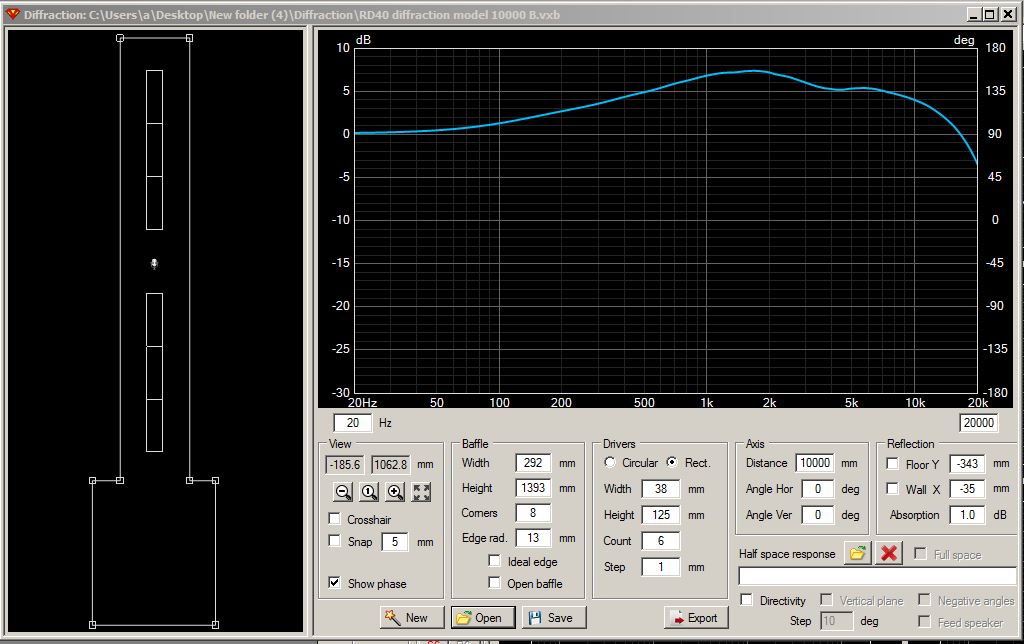
Below: RD40 midrange diffraction model at 10000mm distance:
I used the above six diffraction models to export six BSC FRD correction files. I’m now in the process of loading these correction files into the merger tool for final processing. When done, I’ll post the merger tool screenshots.
Mic should be placed in front of the driver for this process. Correct placement for mid/tweeter, not so much for woofer. You may struggle using that 1m diffraction for its intended purpose when it rolls off the top end significantly like that.
For the big RD40, “correct” placement of mic in the middle is also indicating destructive interference >1kHz at 1m distance. Since the effective radiating surface is so large, you will likely not gather good data with 1m measurement in this way. Longer measurement distance or measuring each driver individually may be required.
1 Like