Wouldn’t theic be on tweeter axis?
The center of the bi- sected ribbon is also the tweeter axis. Is Bill taking something else as the mic placement?
Wouldn’t theic be on tweeter axis?
The center of the bi- sected ribbon is also the tweeter axis. Is Bill taking something else as the mic placement?
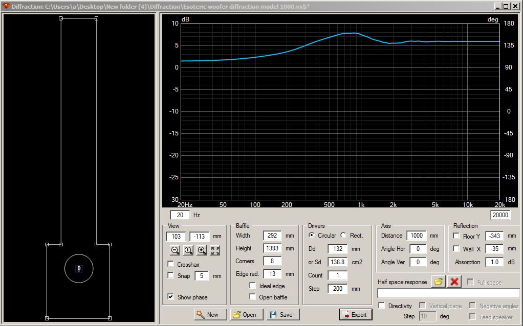
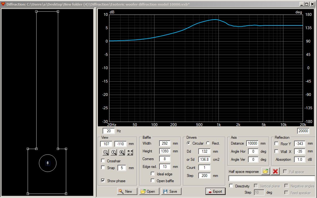
Thanks, reet! Attached are the two revised woofer diffraction models, with the mic moved to the correct position. Response above 1kHz now looks much smoother for the 1 meter distance.
Yes, but only for the RD40 measurement. For the woofer diffraction model, the mic needs to be placed on-axis to the woofer, as indicated by reet.
If you enter the RD60 as a single driver instead of 6 you will not encounter the destructive interference. YMMV for actual 1m measurement.
For mic location - Mic should be placed how you measured it, so it should be on-axis with the driver.
Ya, I think I am probably misinterpreting the following note that I found at the end or the “Diffraction Tool” section of the user manual, which caused me to break it out as 6 drivers. Probably better to enter it as a single driver.
“2. Long planar radiator should be constructed by stacking multiple small rectangular drivers with Step = Height.”
In any event, for the actual 1 meter horizontal measurements, I could try putting a pillow over either the top or bottom sections of the RD40’s and then try to re-measure them as individual upper and lower driver sections. This should get rid of most of the destructive interference. Each upper and lower driver section is about 9.5 inches long.
But then I would have to figure out how to do the vertical spin. I would need to put together some type of temporary outrigger platform to hold the speaker in position as I rotated the entire enclosure on-axis to one of the two driver sections. Not an easy task.
You will have to ask Kimmo about it.
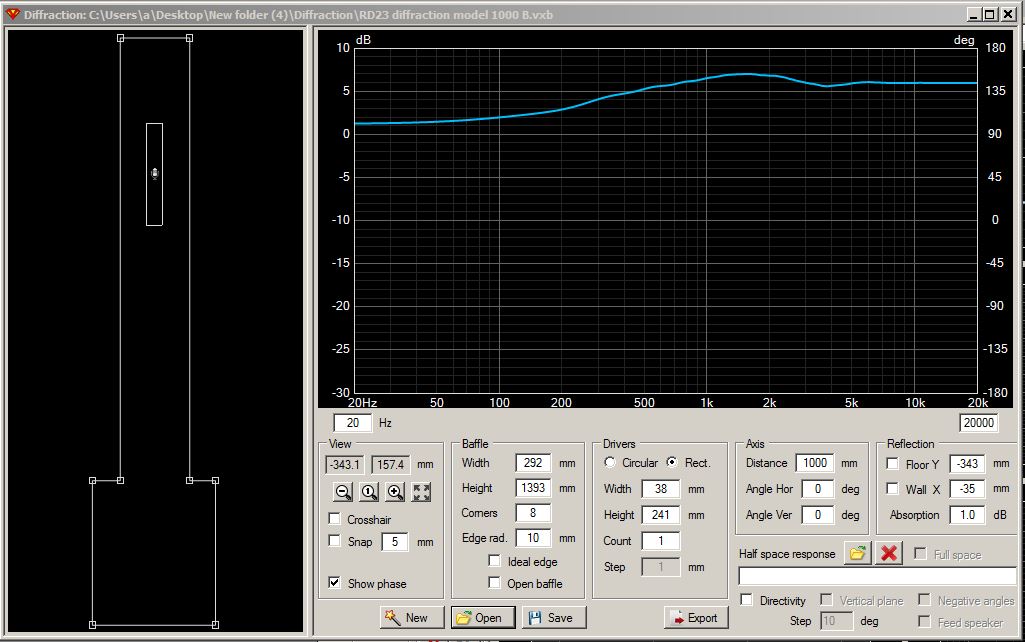
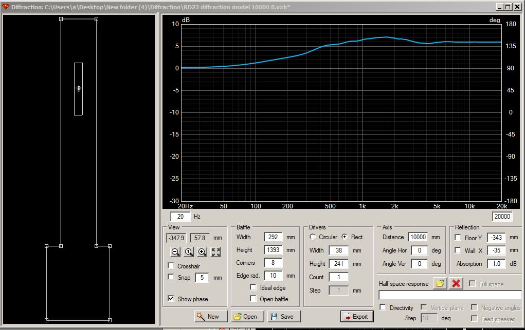
Here are the revised RD23 diffraction models, using a single truncated RD40 driver instead of 6 individual drivers. Looks much better now. Also, I did some testing and discovered an easy way to re-do my FRD measurements to significantly reduce the destructive interference problem at 1 meter. The RD 40 cabinet will balance sideways at the center point of either the upper or lower 9.5" long sections using a single 12" bar clamp. And I can block off the upper or lower sections, one at a time, using the same Frost King air conditioner weatherseal that I used to originally truncate the drivers. Just add another 9.5" of weatherseal material and seal it in position with masking tape. No need to use a pillow. So I’ll redo the measurements tomorrow and then start creating the merger models.
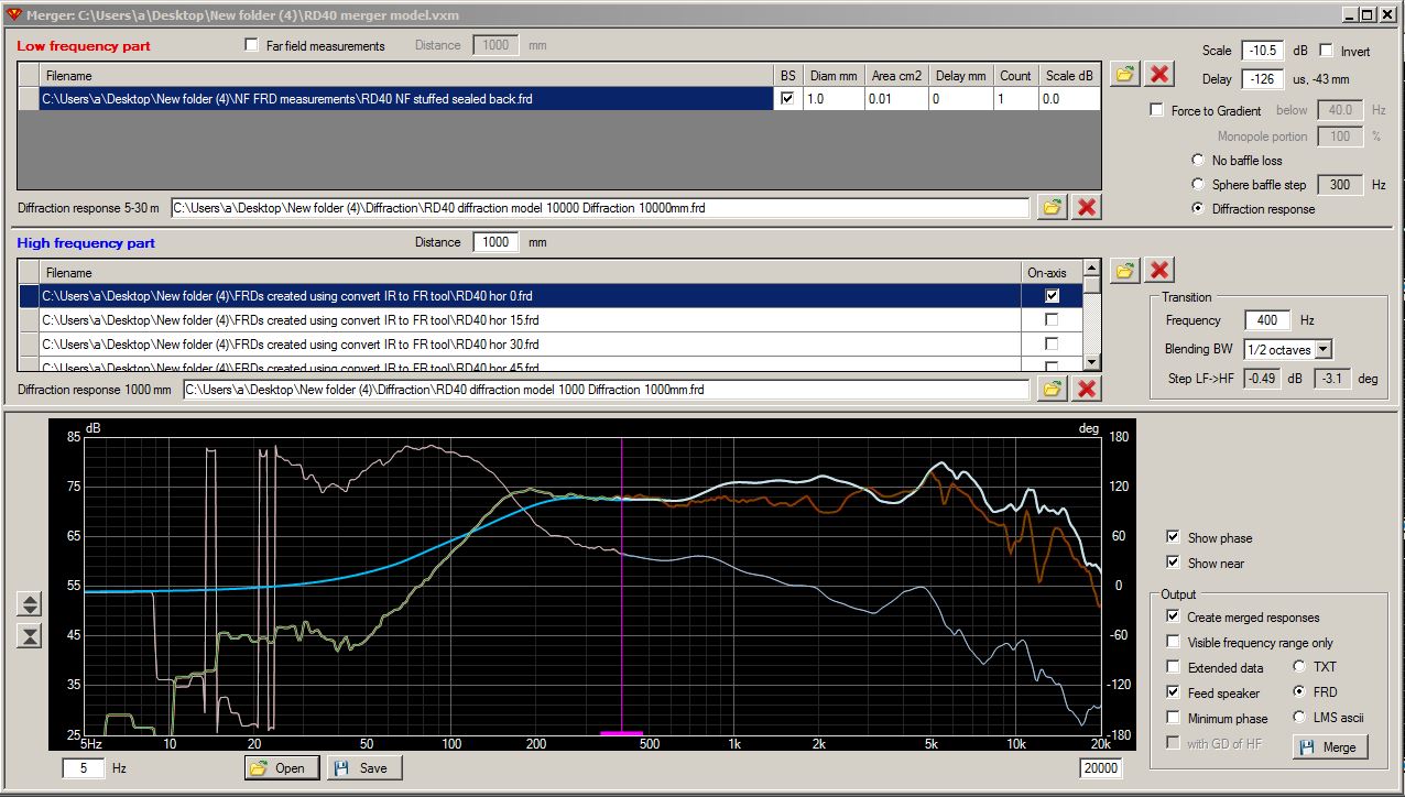
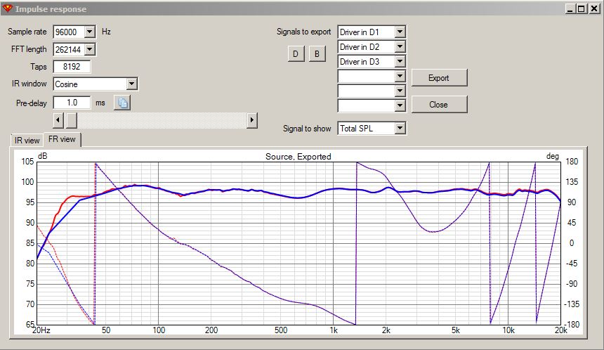
Here is the merger tool model for my RD40 measurements, with the tweeters mounted in the center but WITHOUT foam blockers at the top or bottom of the drivers. The model merges a diffraction corrected near field (NF) RD40 measurement with a set of diffraction corrected far field (FF) RD40 spin measurements.
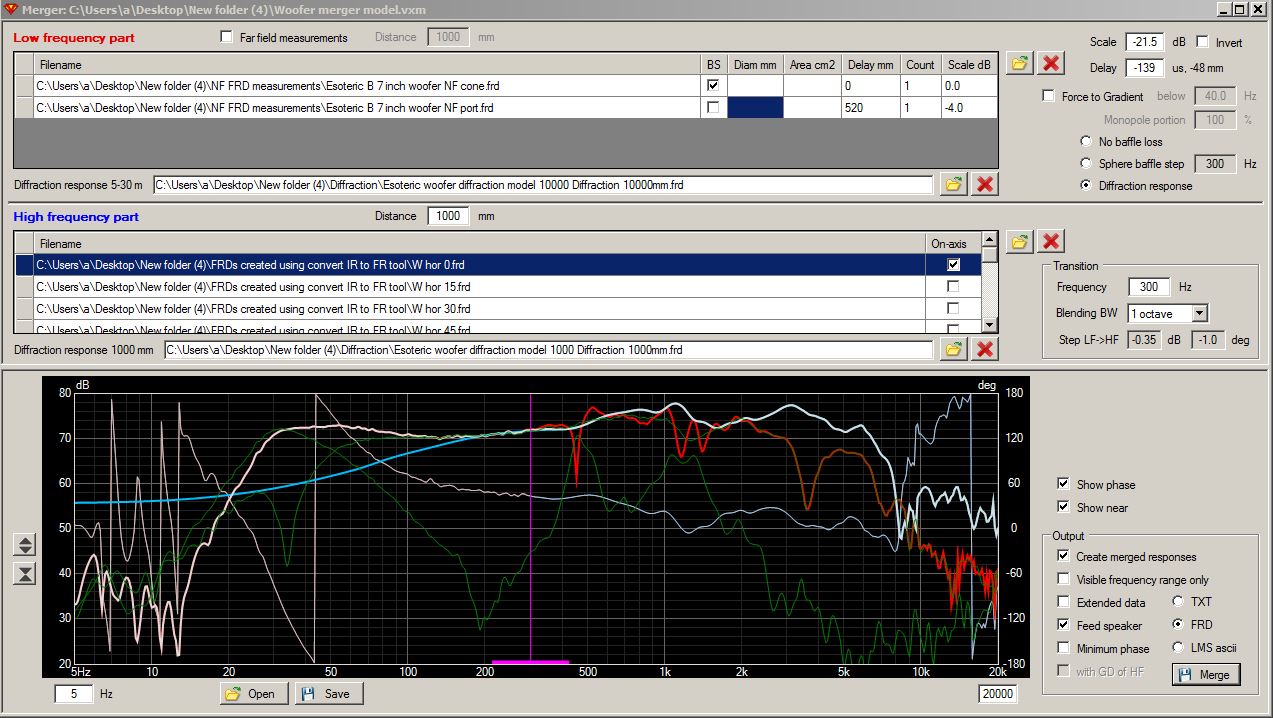
And here is the merger tool model for my Esoteric 7" woofer measurements. The model merges diffraction corrected near field (NF) cone and port measurements with a set of diffraction corrected far field (FF) woofer spin measurements.
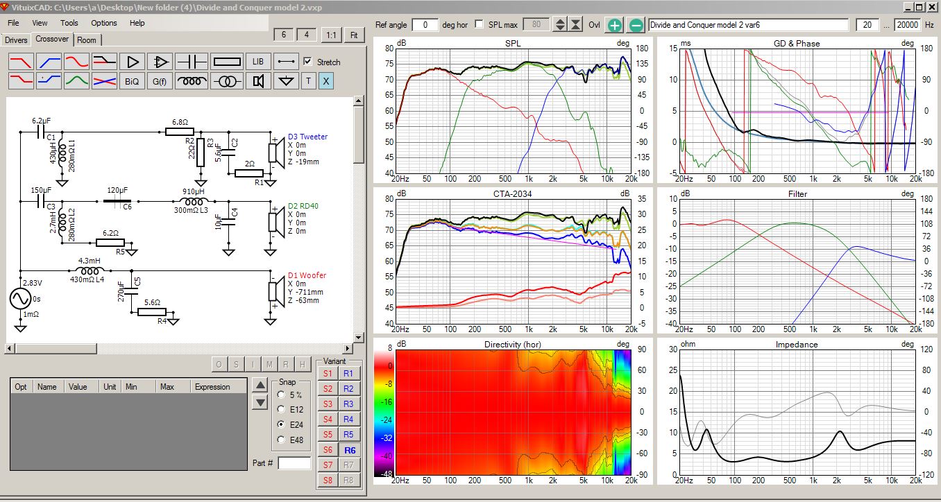
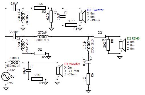
And here is my first attempt at a crossover, using data generated from the above two merger models and the unadjusted tweeter frds:
6 pack with horizontal heat map:
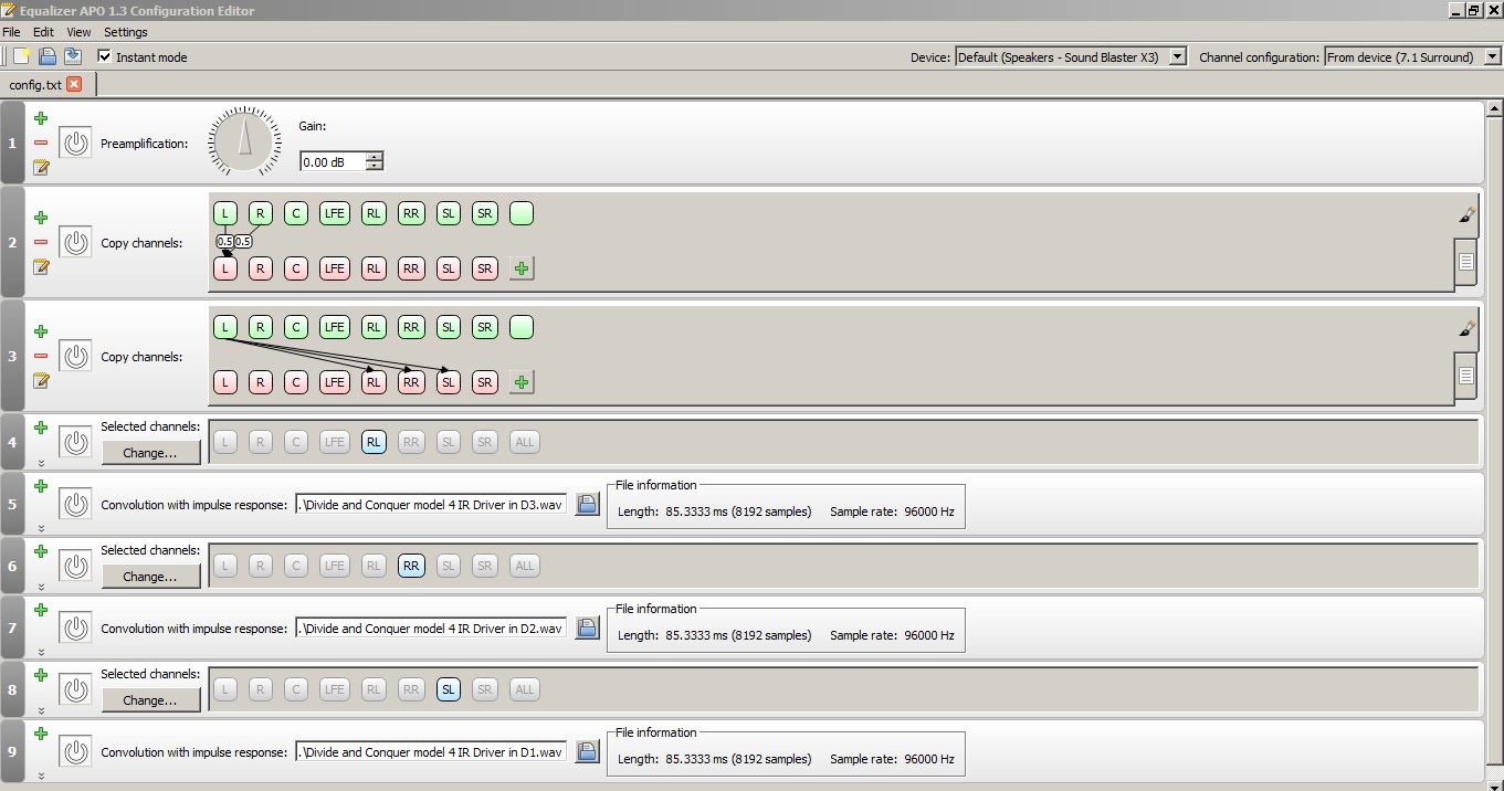
I’ve been listening to the exported digital version of the above xover for a while now and I’d like to share my listening impressions so far.
So, back to the drawing board. I think I’ll attack the weak bass problem by moving the woofer crossover a bit higher. Currently at 165Hz. And I’ll attack the treble glare problem with a notch filter.
I made several xover revisions and it is sounding really good now. 18 parts. Very good tonal balance from top to bottom. Razor sharp detail thoughout the mids and highs without sounding harsh. The midrange, which previously sounded shouty, now blends well and does not call attention to itself. I’m very happy with this new version, so I think I’ll start putting together a parts order. Here are a few details on the revision. Let me know what you think.
I pulled down the midrange by about 1 to 2dB with an L-pad (R7/R8). I also moved the lower xover up from 165Hz to 200Hz, which helped things along as well. Now the bass from 30 to 200Hz blends very well with the midrange. Bass is punchy and full, not somewhat thin like it was before.
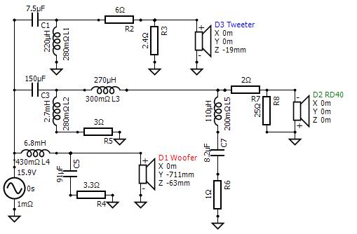
I moved the upper crossover up from 2500Hz to 3300Hz and then added a 5.6kHz notch filter (L5/C7/R6) on the RD40 to suppress this driver’s nasty self-resonance problem.
I adjusted components to flatten and lower the bulging on-axis response in the 900 to 2kHz region. Sounds much smoother now without the shouty, honky type quality.
I also adjusted the tweeter parts to smooth things out and to match the new lower midrange level. Moving the xover higher helped to flatten the on-axis dip at 5-7kHz, while, at the same time, keeping the power response from bulging too high and creating a conflict. There is a blip in the directivity index at the new xover frequency, but I don’t seem to be able to hear this in listening tests.
The revised crossover meets the Indy 4 octave rule for 3 ways. 200Hz x 16 = 3200Hz. So I’m good to go for the competition.
I should note that I have now completely abandoned the idea of placing upper or lower foam blockers on the RD40’s. I set up a model and attempted to design an xover with the foam blocker version, but it simply would not work. What happened is that the foam blockers dropped the RD40’s sensitivity by about 2 to 3dB at lower frequencies, but then boosted the frequency response at higher frequencies. With the foam blockers in place, the overall sensitivity dropped so low in the 200 to 500Hz region that it became necessary to put a padding resistor on the Esoteric 7" woofer to match output levels. I didn’t want to do that, so the foam blockers had to go!
Even when using a higher 3300Hz crossover without the foam blockers in place, the difference in sound from a seated to a standing position is not very much at all. In fact, the difference is less than the previous xover that used the 2400Hz xover. I think this has something to with installing the 5.6kHz notch filter, but I am not sure.
Is C2 really required? 15uF seems larger and lower than xover point there.
Yes, C2 is carefully adjusted to shape the tweeter’s roll off knee, in combination with the values selected for R1 and C1/L1. If I attempt to lower the value of C2, an on-axis bump up at the crossover point starts to develop.
Grumpy Roemer would be pleased to see your Zobel! Just joking, or am I? lol
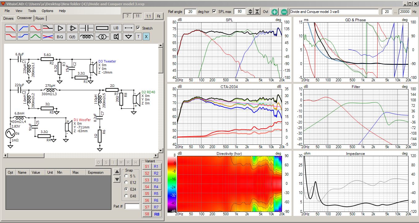
Ya, I guess both of you are correct. The 15uF zobel is not really needed at all. Thanks for pointing that out. Now down to 16 parts on my order. And the vertical directivity at the xover looks a little bit better now as well!
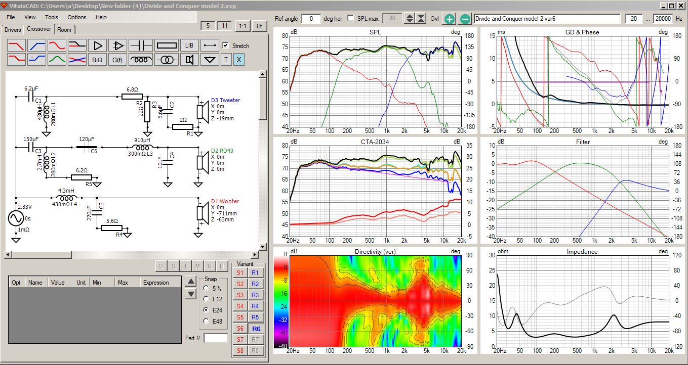
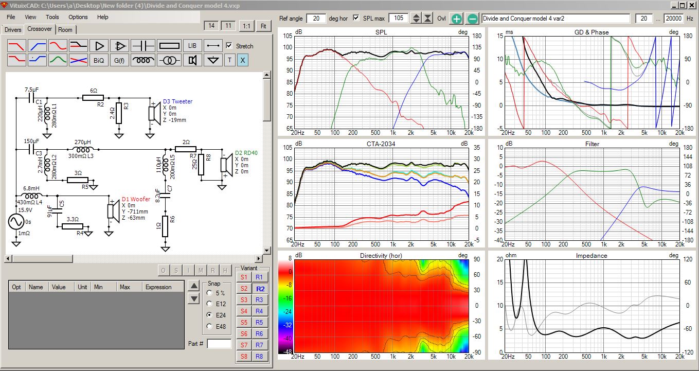
Revised 6 pack:
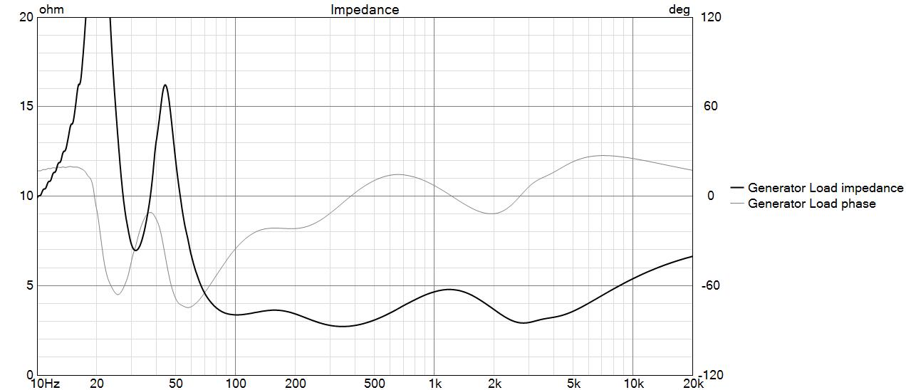
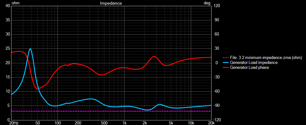
Dipping to 2.5 ohms in a few places there, Bill. The Crown won’t care, but 4 ohm stable amps might.
Bill has that big Heathkit arc-welder amp - no problem!
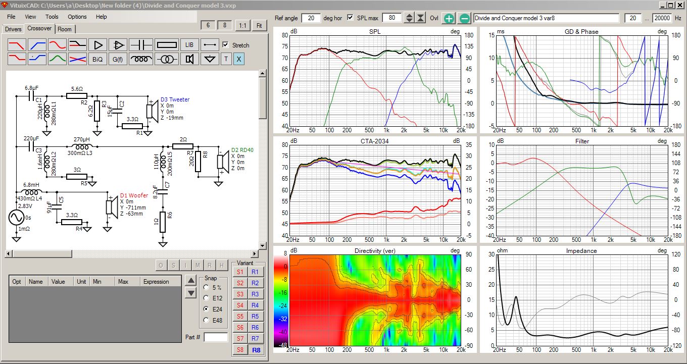
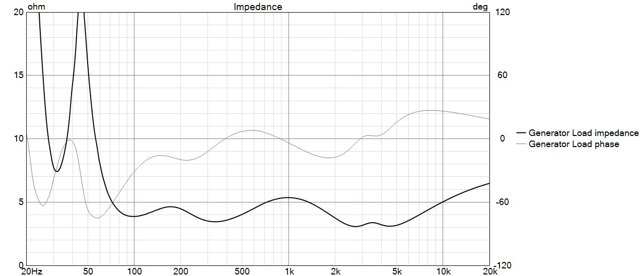
Another day, another revision. In my latest model, I got the minimum impedance at 350Hz up to 3.4 ohms (previously 2.7 ohms). Xover is still at 200Hz with roughly the same slopes. I shifted to a smaller cap and a bigger inductor. Minimum impedance at 2-5kHz is now up to 3.1 ohms (previously 2.7 ohms). My amplifier will be much happier now! Listened to the revised xover and it sounds just as good. Think I am ready to order parts.
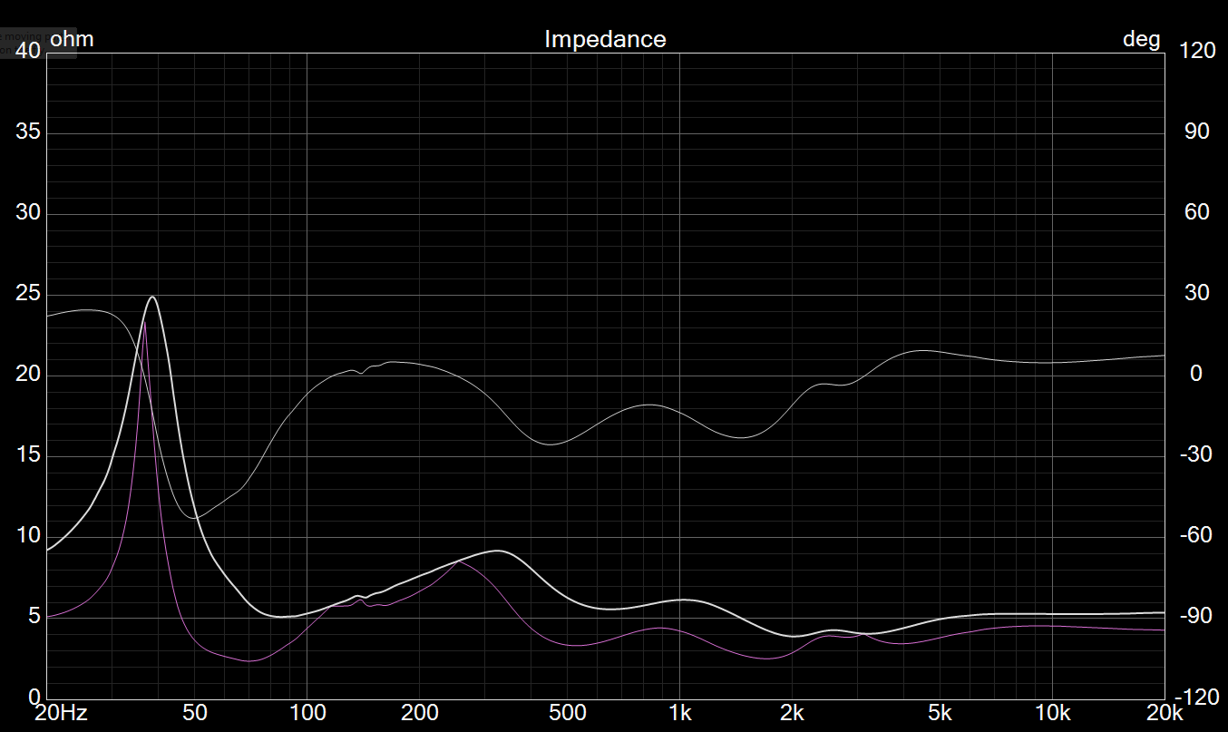
I know that you can just zoom in and look carefully to see what the impedance is doing, but if I am trying to make sure not to cross some threshold, this is what I do…
Easier method is to simply “add new driver” to your project, it defaults to 8 ohm flat. Connect the driver in the crossover, then adjust scaling in driver tab to adjust flat impedance to whatever threshold you want, then right click and “save as overlay”, then remove driver from the project. Also, make sure to define the minimum impedance you’d like to achieve in the Optimizer. For my own speakers, I usually try to stay above 3.5 ohm if I can help it.
However, minimum impedance is more complex than a flat line minimum threshold. Those phasey things matter too so EPDR view can help with that.
For an example, the following speaker has a minimum impedance of 3.9 ohm at 2kHz, however minimum EPDR occurs at 70Hz. Also consider the low frequency portion has vastly higher current demand due to spectrum of audio falling at least 3dB/octave.