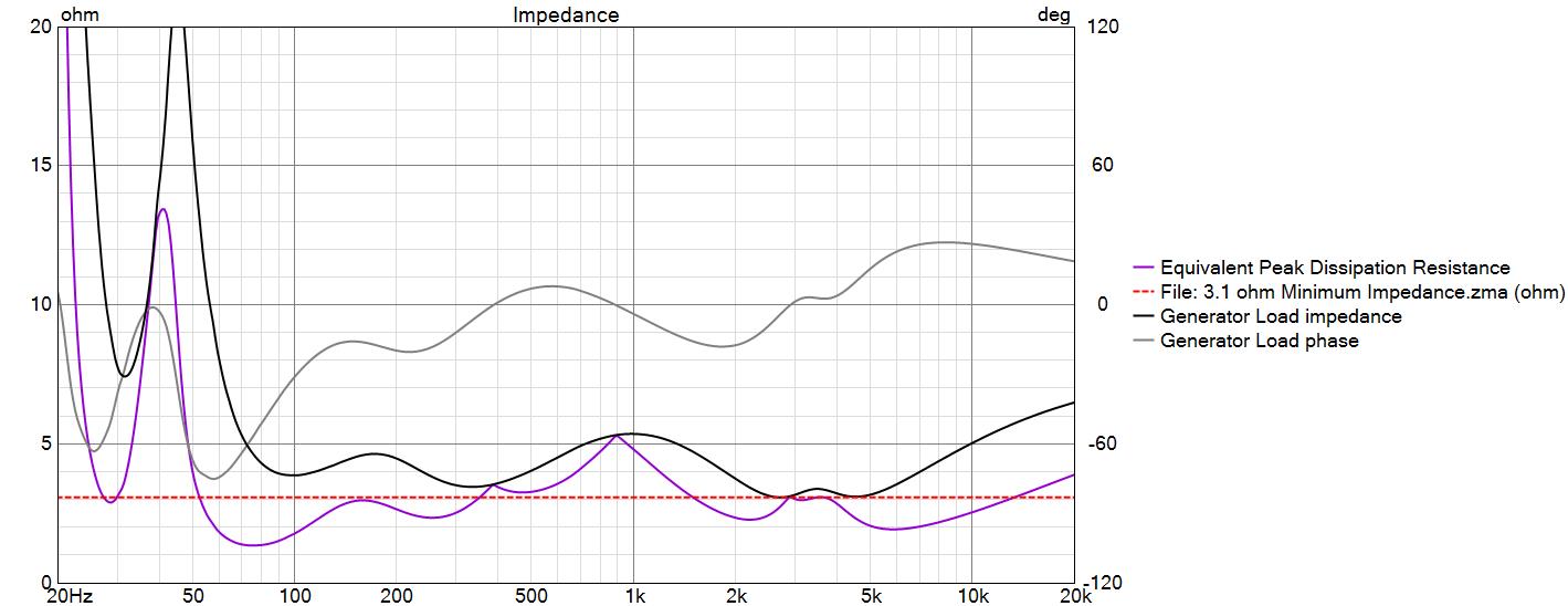
Thanks for the tips! Here is my latest crossover revision with a 3.1 ohm target overlay and EPDR curve added. Looks like I have alot of current flowing in the 60 to 100Hz region! ![]()
I’ve been back and forth on whether I care about this for a while. I don’t have any tube amps, but I always ignore the impedance ratings on the amps and have never had an issue I could notice. For example I have been running Schiit Vidar 2s in mono which are only rated into 8ohms and I would crank my Tekton Double Impacts on them which dip to 2.3ohms.
Thus far, when it comes to the trade-offs in my crossovers I’ve been very willing to let the impedance fall. At least until I cross the 2.0ohm line. I’m frequently below the 2.5ohms in at least one spot.
That said, if the impedance doesn’t need to be low, I keep it high like Bill is doing here.
1 Like
For clarity, low EPDR doesn’t indicate any more current flowing than otherwise, it’s an indication of thermal “dissipation” load on the output transistors for a traditional class-AB amp. If you’ve ever wondered why amps with enormous power supplies perform better in the bass range…
1 Like
All of my amps are Class-D (PWM). After quickly perusing a couple of Rod Eliot’s Class-D articles it appears to me that EPDR isn’t a big thing for Class-D.
Class-DGAF ![]()
1 Like
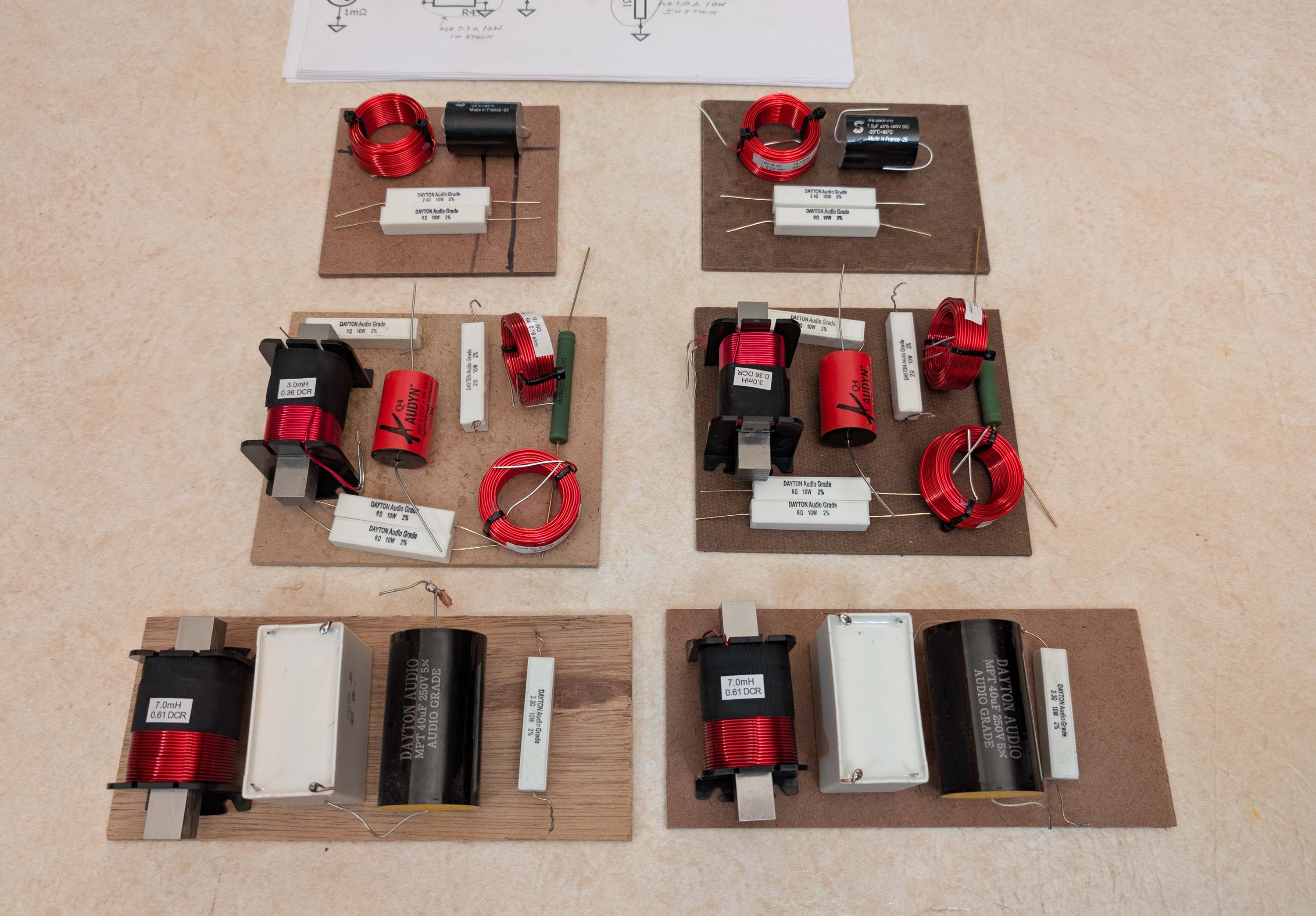
Crossover layout underway. The lower two woofer boards will go on the bottom of the woofer cabs. The middle two midrange boards will go on the bottom of the RD40 midrange cabs. And the upper two tweeter boards will be glued right behind the tweeters, in about the middle of the RD40 cabs.
6 Likes
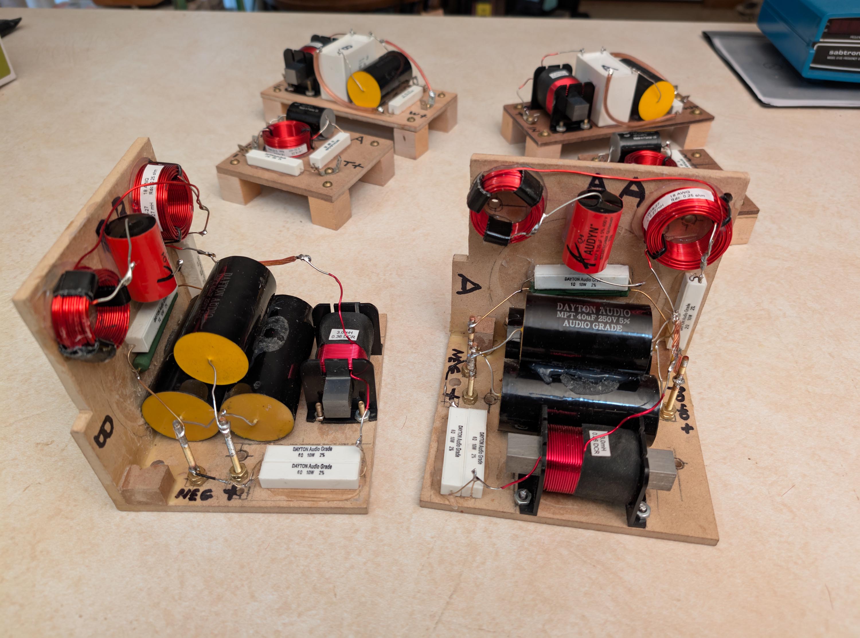
I finished the crossover boards today. I’m now ready to install them in the cabinets.
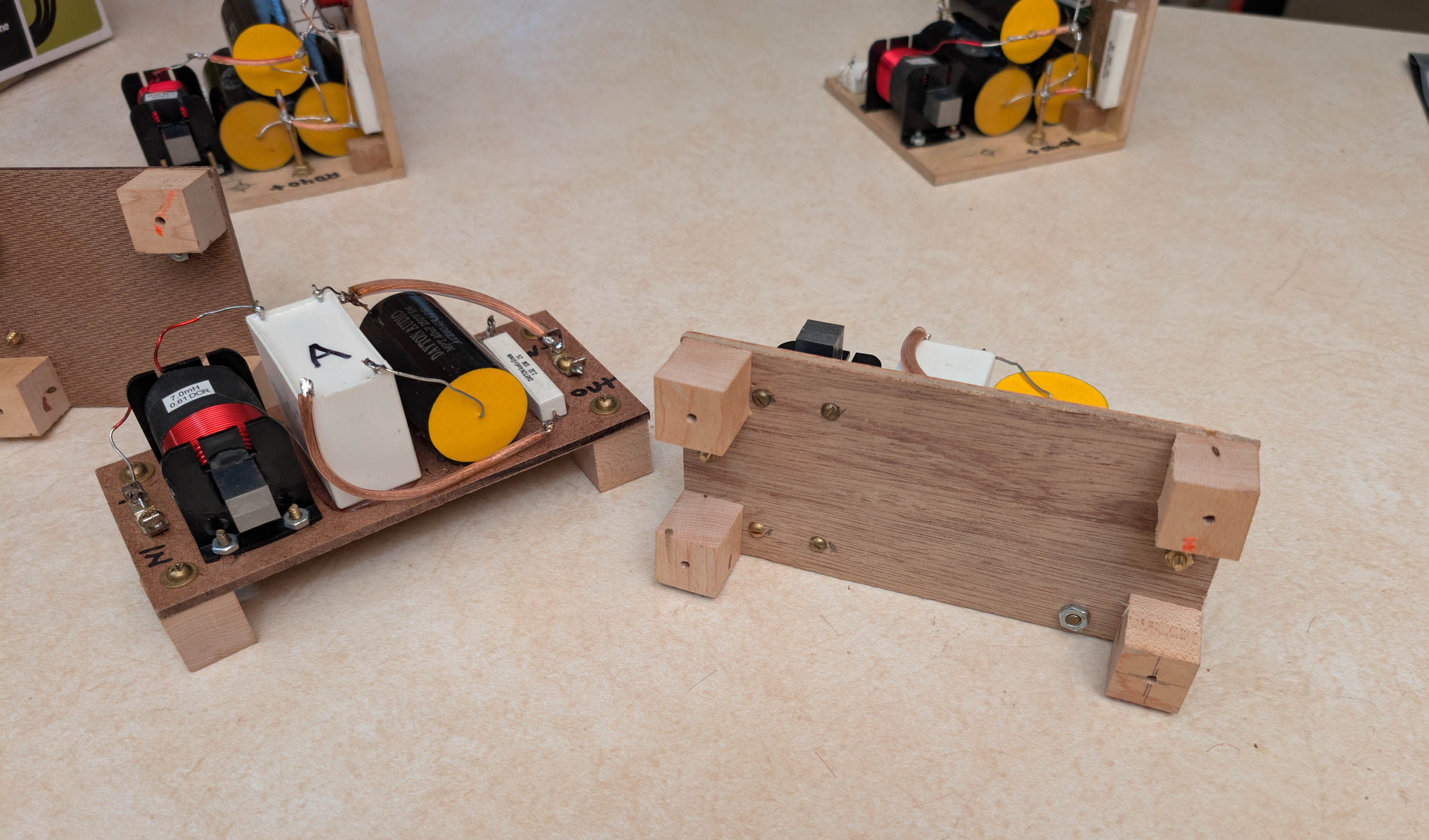
Below pic: I changed over to a dual right angle midrange board arrangement to accomodate the 3 big PP caps. (These caps were missing from my previous pic above). This dual board will mount at the bottom and one side of the midrange cabinet with 4 screws.
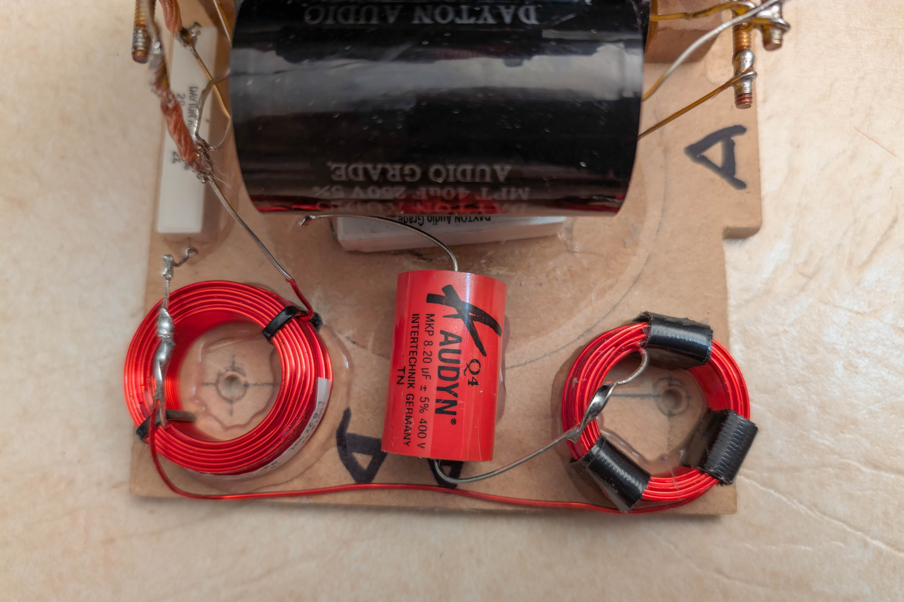
Below Pic: Two of the screws are located inside two of the air core inductors. I will need to use brass screws here to avoid messing up the inductance. The smaller inductor, with 3 strips of gorilla tape holding it together, was modified by unwinding it down to 0.11mH from 0.15mH.
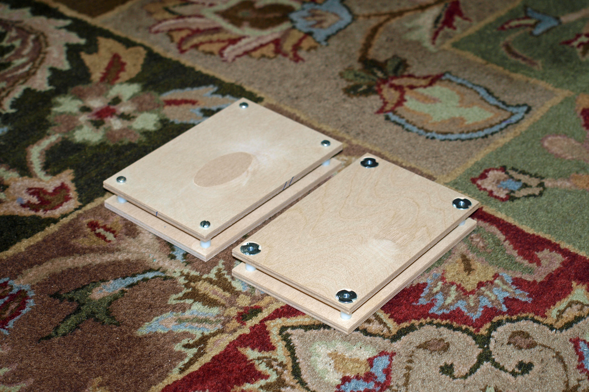
Below pic: I added four small “feet” to the tweeter boards, held in place with 4 brass screws. Plan is to add glue to the bottom of the feet and press it into position. Once the glue sets, the board can be removed later on for servicing, if needed, by removing the four screws. This was not my idea. I saw someone else do this in another thread and thought it was a good idea. Can’t remember where I saw it, but I think it was one of Ron’s build threads.
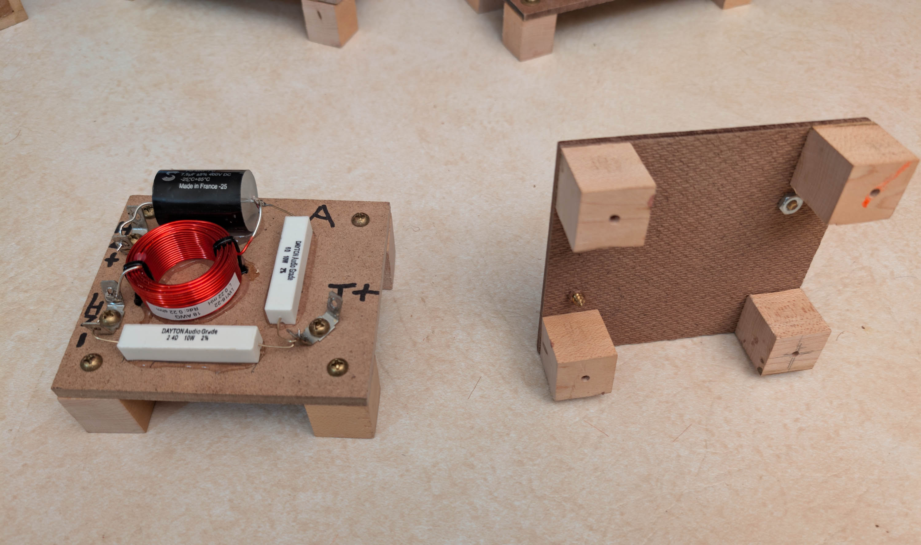
I also added four small “feet” to the woofer boards. Same idea.
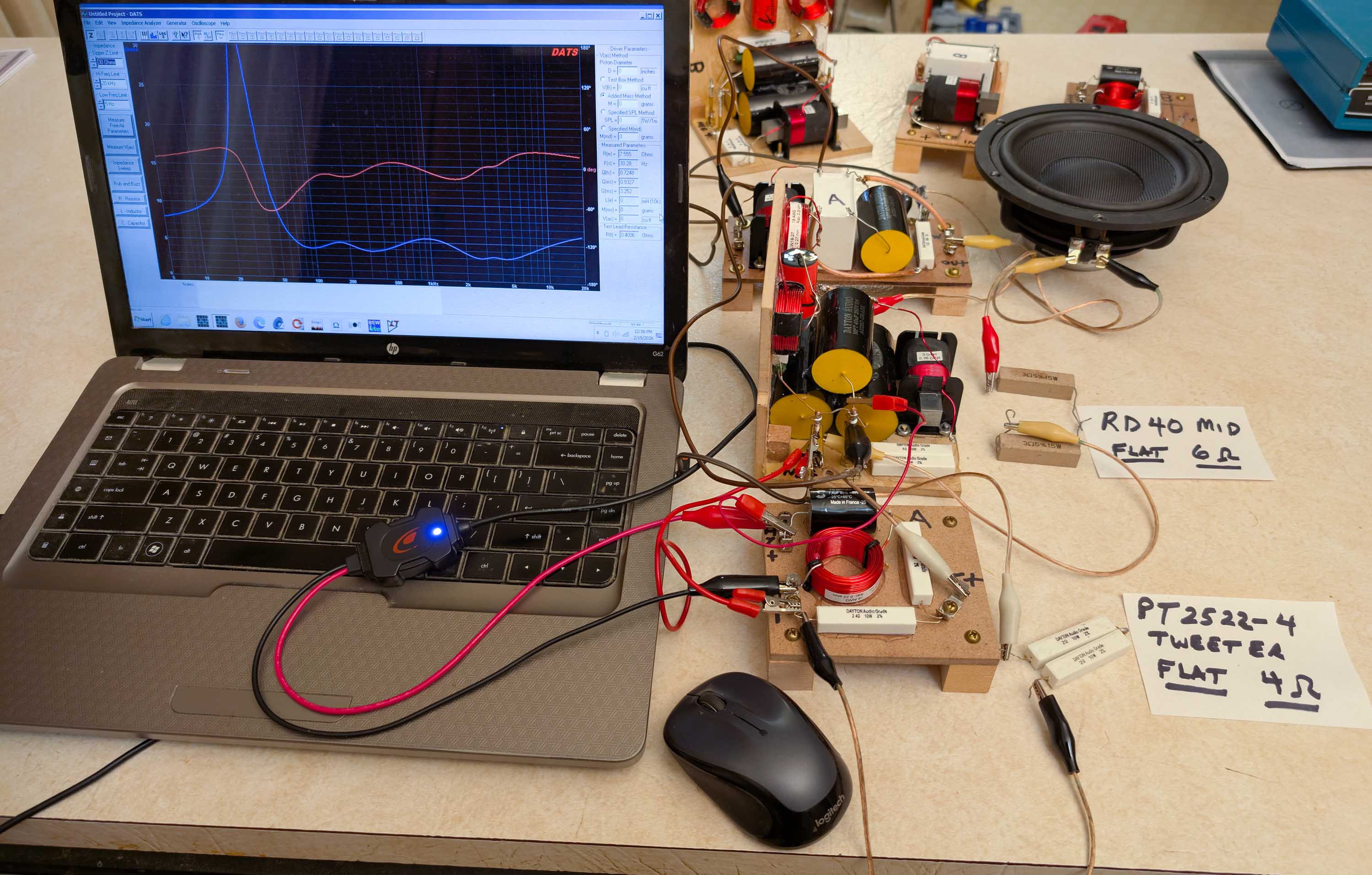
Once the boards were all soldered up, I set them up for a DATS V2 test. I connected a 4 ohm dummy load to the tweeter board and a 6 ohm dummy load to the midrange board. Then I connected an Esoteric 7" woofer to the woofer board. I paralleled all the inputs and ran an impedance sweep. I get a perfect match to my model (except the woofer has a single peak instead of two, since it is not mounted in the final cabinet). So it looks like my assembly and soldering was error free.
3 Likes
I didn’t use wooden blocks. I countersunk t-nuts into a piece of plywood and pressed some nylon spacers over the t-nut.
Ron
2 Likes
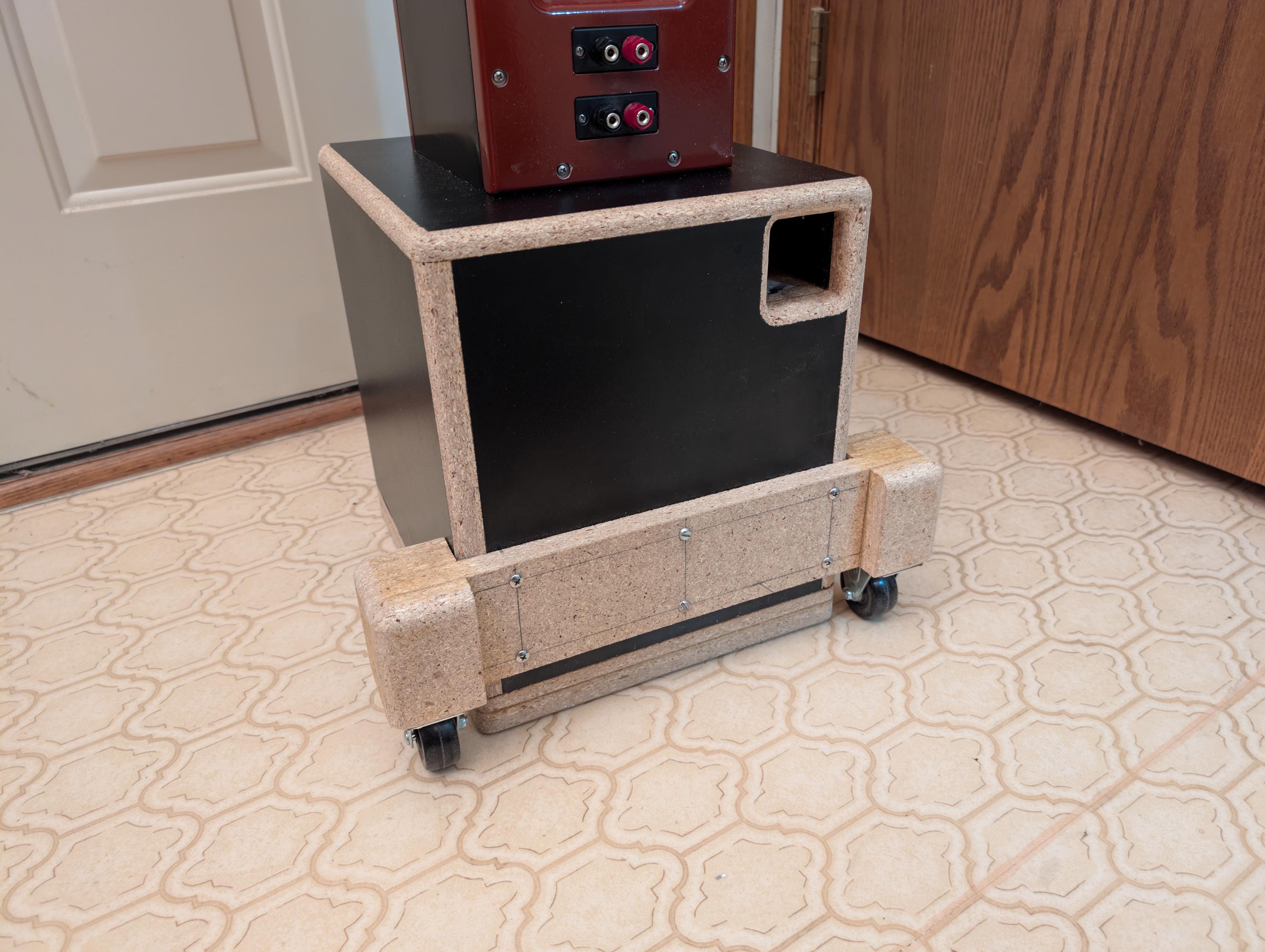
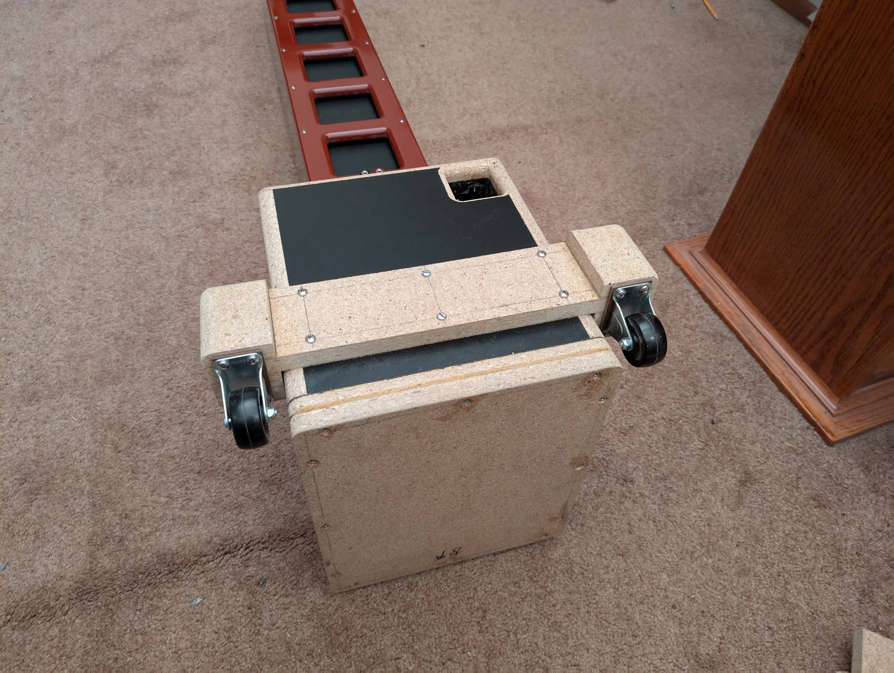
Today I tested a set of 2" non-swivel casters. They seem to work very good. The entire caster assembly can be quickly bolted on or removed as needed. I designed the assembly to have a 14" track width and 1/2" rear corner floor clearance. At a tilt of roughly 45 degrees, the speaker runs smoothly across hard floors or thin carpeting. Can’t wait to test it out in the parking lot and hallways when I get to InDIYana, SDC, and IowaDIY later this year! ![]()
6 Likes
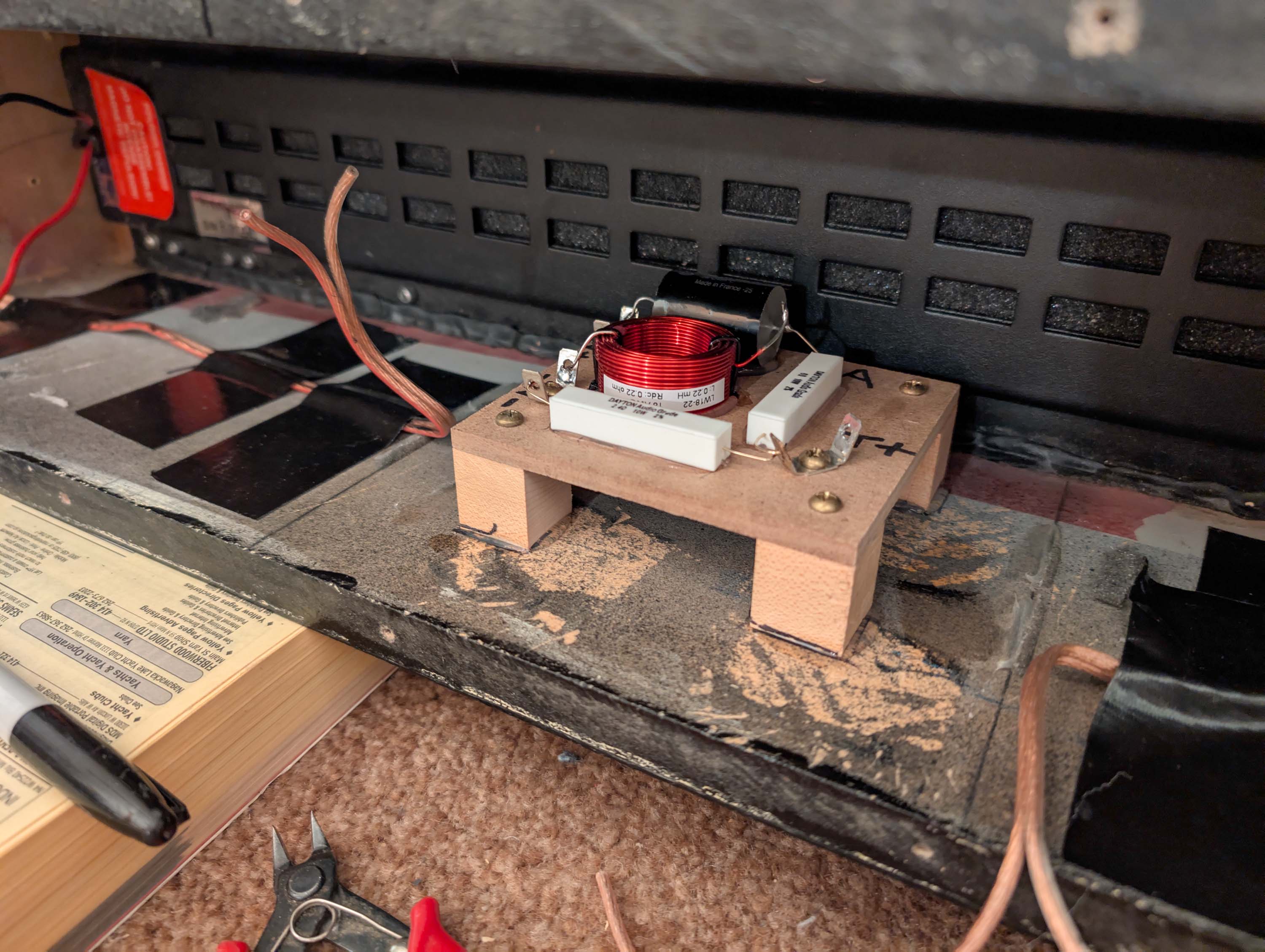
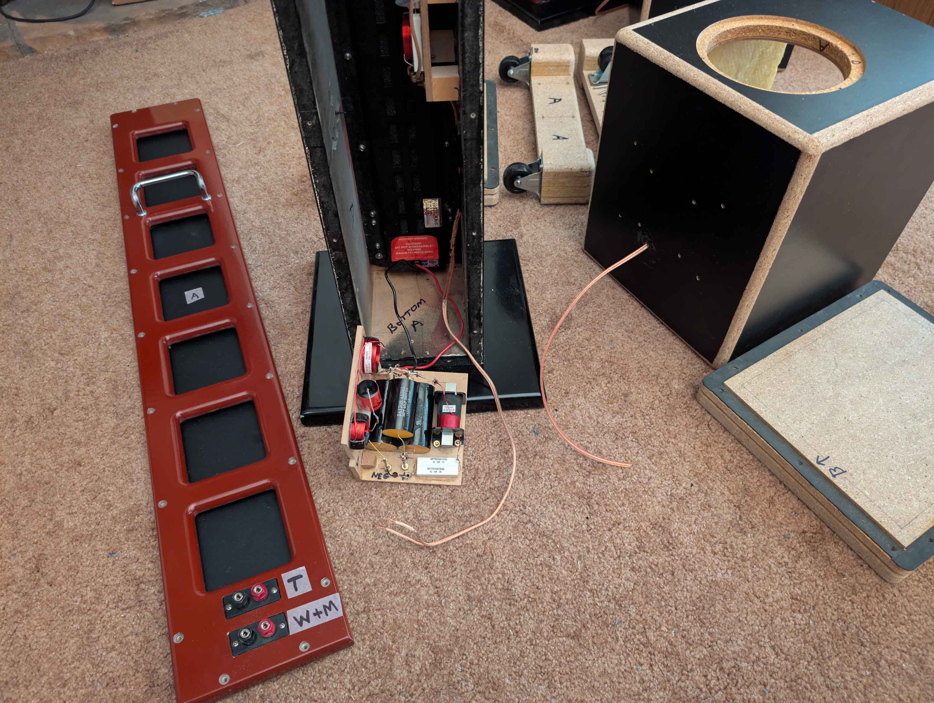
Here I am installing the tweeter xover boards into the RD40 cabinets with 100% silicone sealer. Put a big dab of silicone on the bottom of the 4 wooden corner blocks and squished it into place. Now I’m waiting for the silicone to set up so that I can solder the input and output wires.
I had pre-installed 16ga OFC wire coming from the tweeter to the bottom of the cabs using gorilla tape. So I needed to remove the tape in two spots and cut the wire. The gorilla tape was extremely difficult to remove. I had to scrape it off with a sharp chisel. You can see the marks where the tape pulled up the old overspray paint as I attempted to pull it off.
2 Likes
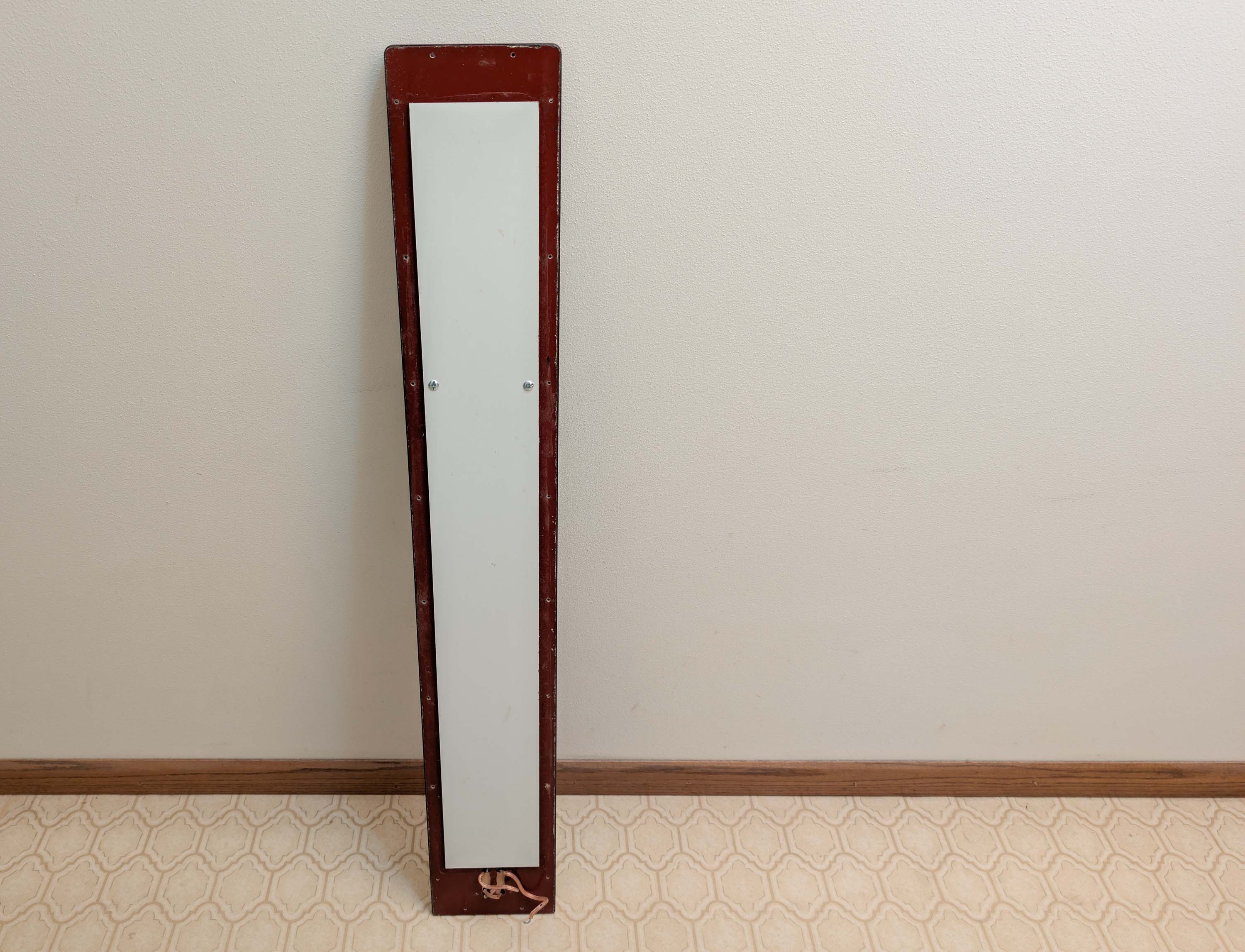
While I’m waiting for the silicone to dry on my xover boards, I drilled two holes in the back panel and mounted a handle 12" down from the top.
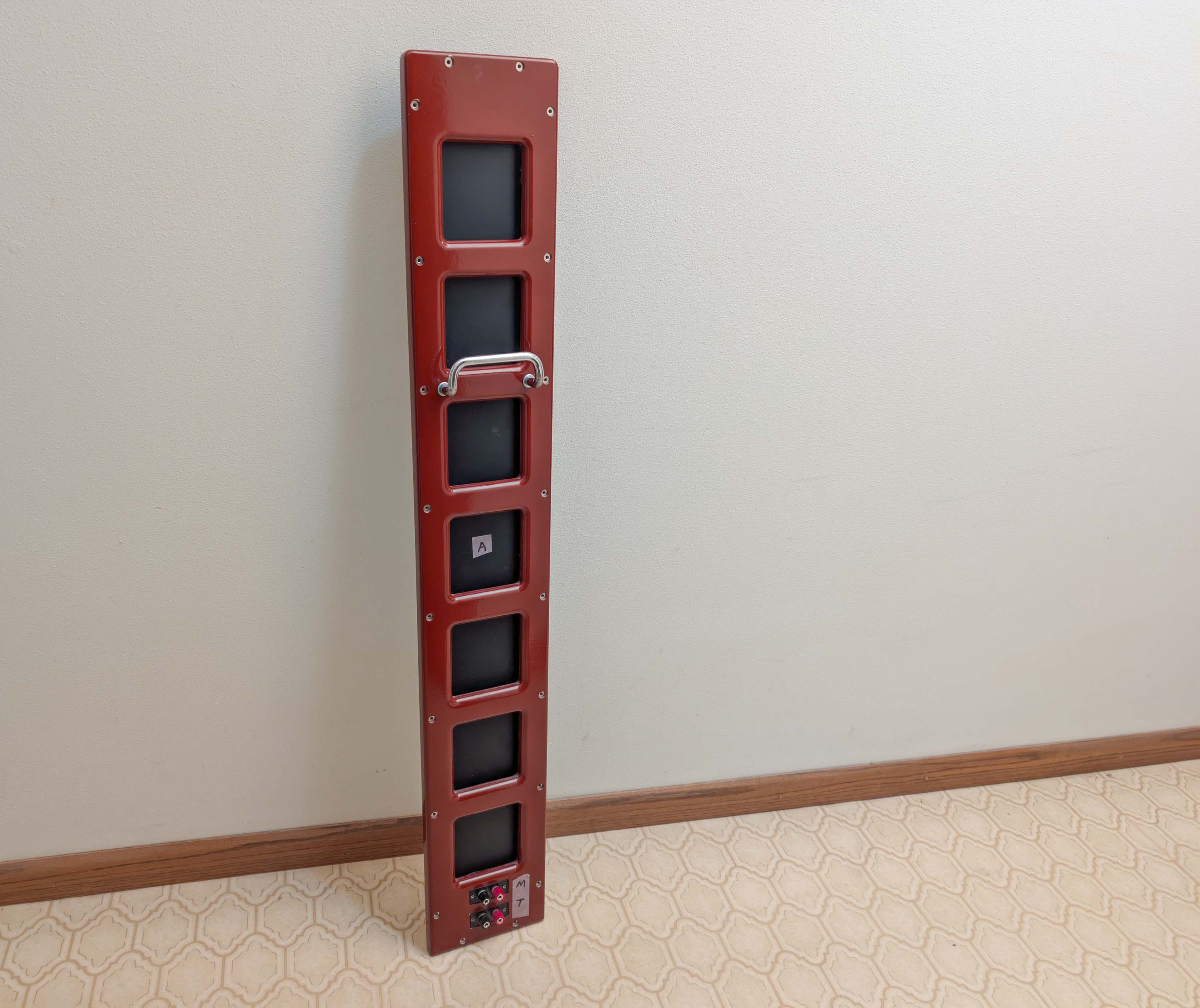
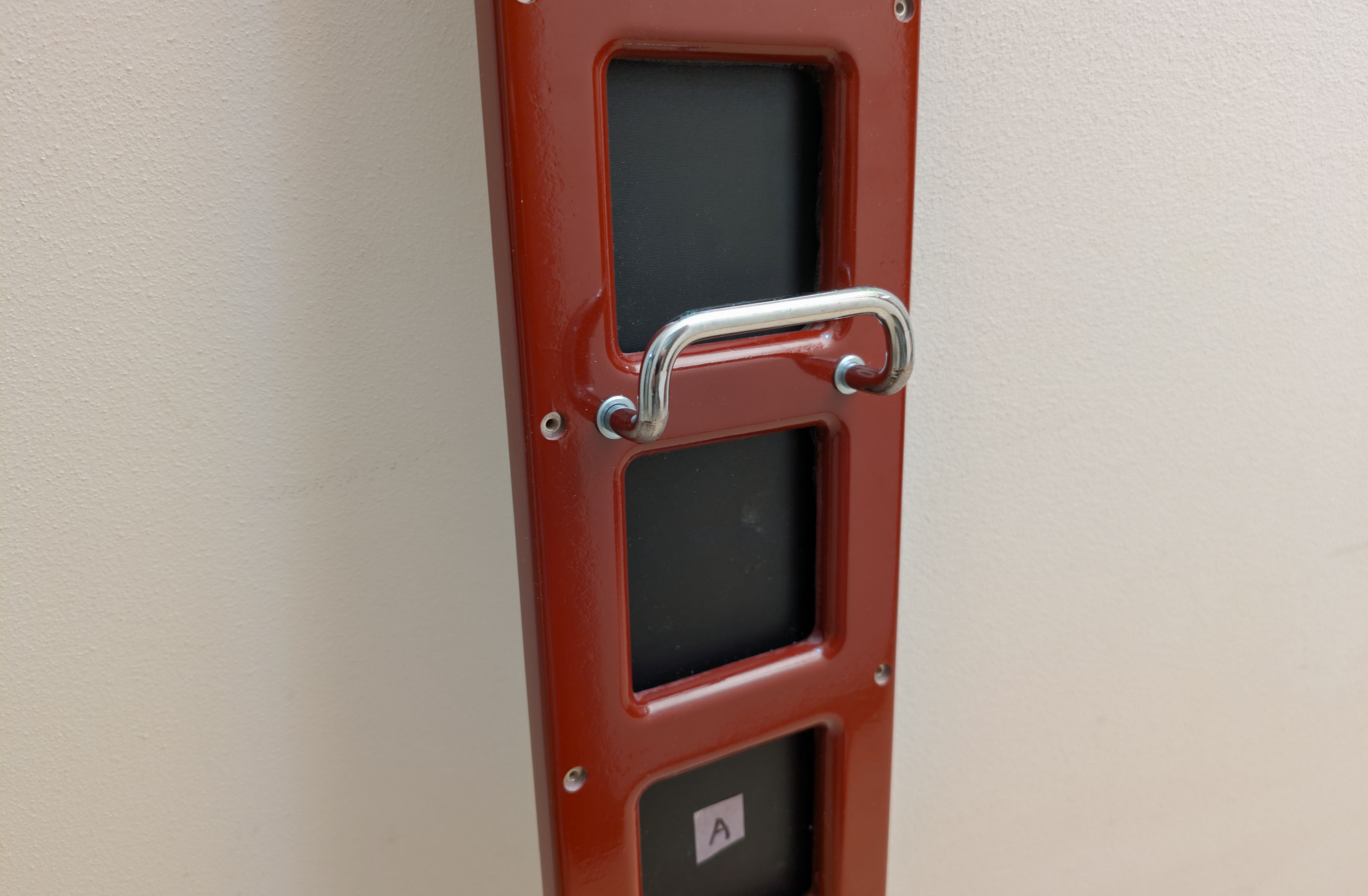
View from the other side. The aperiodic holes are now sealed off with a long strip of 1/4" thick HDF chalk board.
1 Like
Nice functional touch with the lift handle!
1 Like
I’m currently mounting the midrange crossover boards and trying to decide if I should bi-wire the inputs or simply parallel all the drivers up to just one of the two dual banana input jacks. The back panel has an extra pair of input jacks that are “left-overs” from my previous Plan-Tanic speaker build. I was using the 2nd pair of banana jacks as a pass-thru for the plate amplifiers, so they are no longer needed with this build. Is there any advantage to bi-wiring the inputs? I could connect one set of jacks to the tweeter crossover inputs. And the other set of jacks could be connected to the M+W crossover inputs. External shorting straps could then be used to switch back and forth between standard wiring or bi-wiring.
I found this old thread on PETT, which seems to indicate that bi-wiring speakers is a complete waste of time. So I think I will just parallel all the drivers to just one of the two pairs of banana jacks and leave the other pair disconnected.
https://techtalk.parts-express.com/forum/tech-talk-forum/1481211-building-biamp-biwire-speakers
1 Like
Bi-wiring, yes probably of little value (some see some value in cable selection, but that’s way above my pay / hearing grade).
But you could use jumpers and leave open the option of bi-amping for down the road…
That’s what I figured. Another idea would be to wire up the extra pair of banana jacks to the tweeter padding resistor. Then I could adjust the tweeter level to taste without having to tear the speaker apart each time.
2 Likes
…or for a bit of nostalgia (thinking the Yamaha NS-10), you could drape a roll of TP ![]()
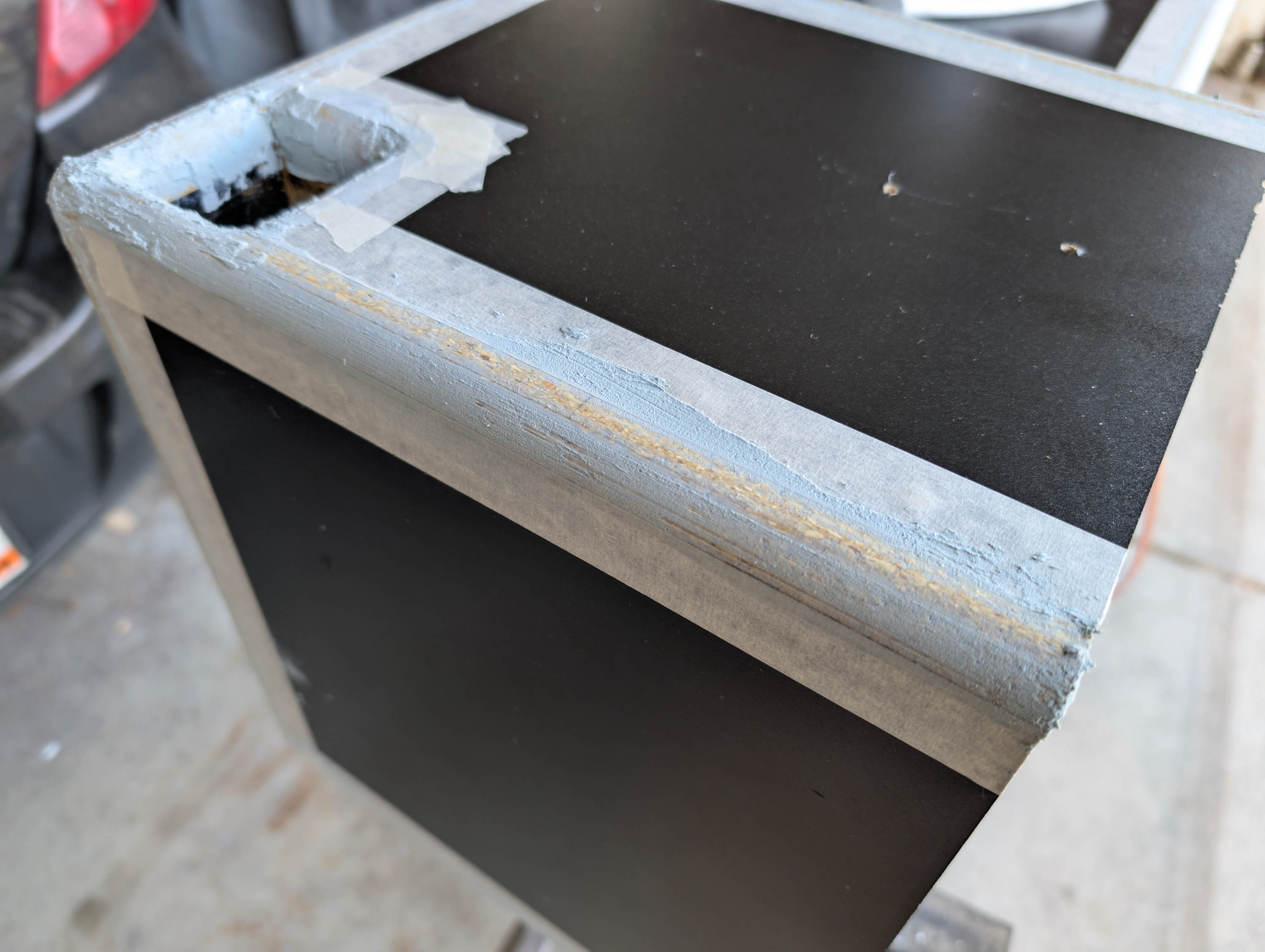
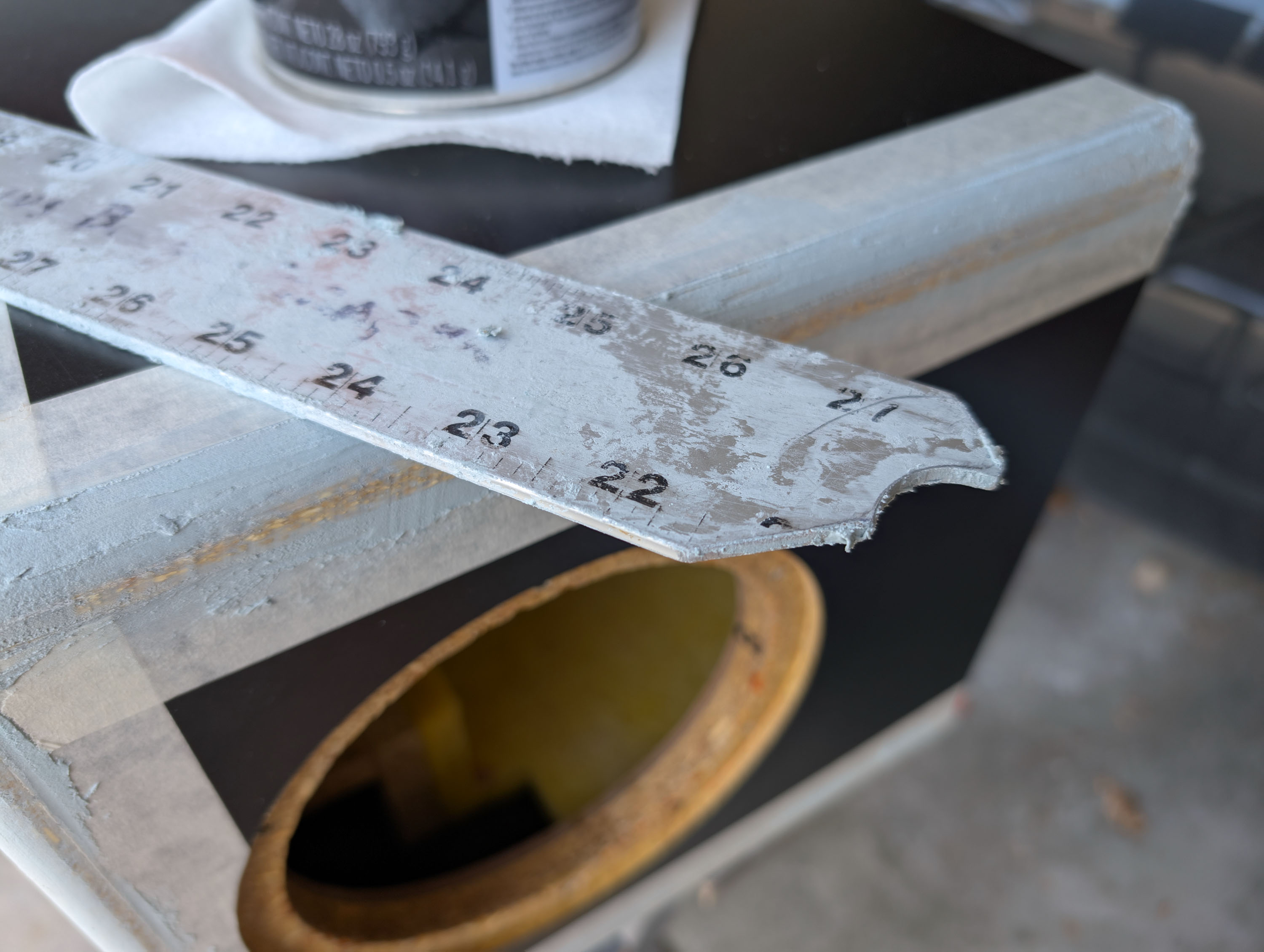
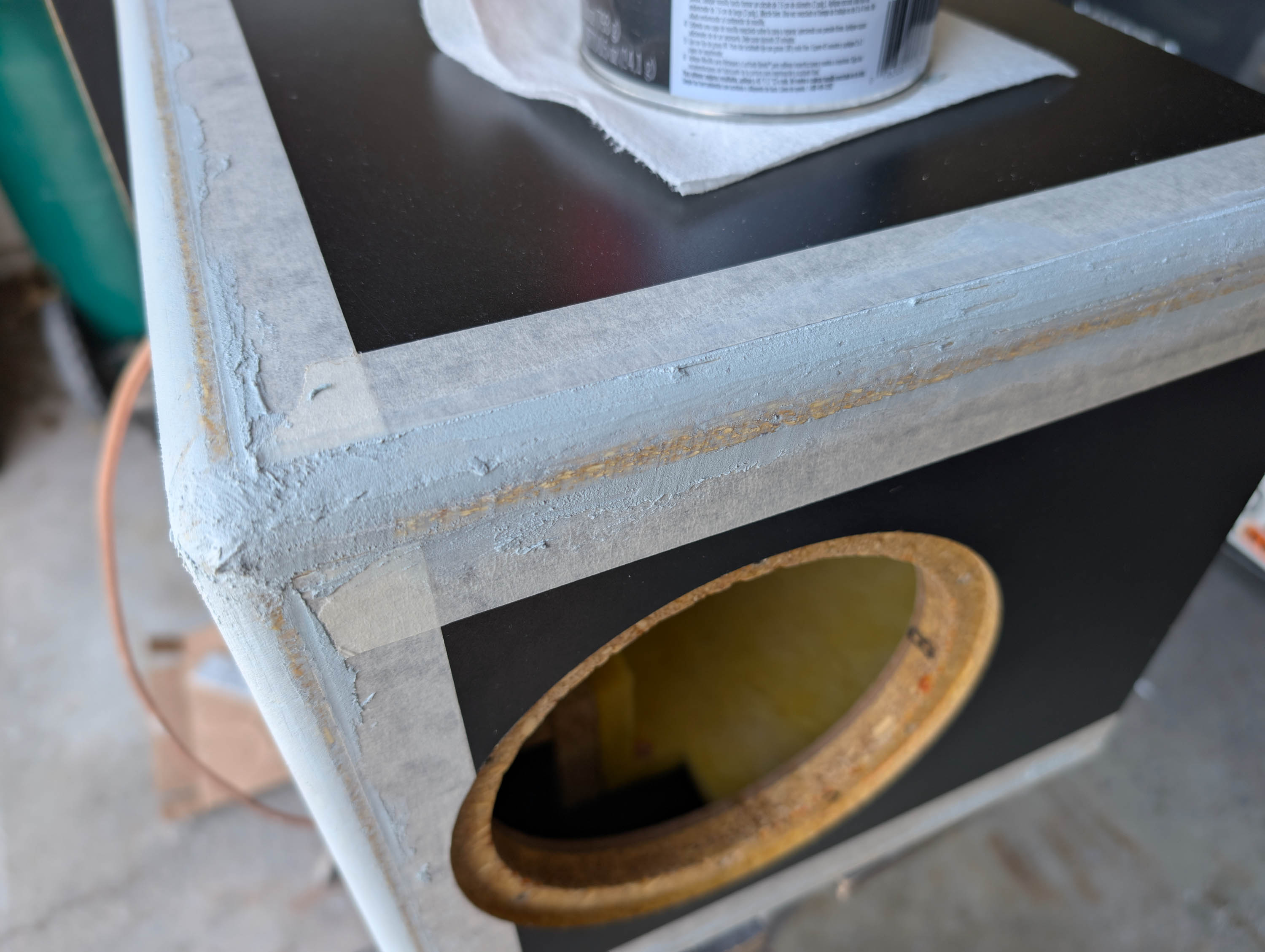
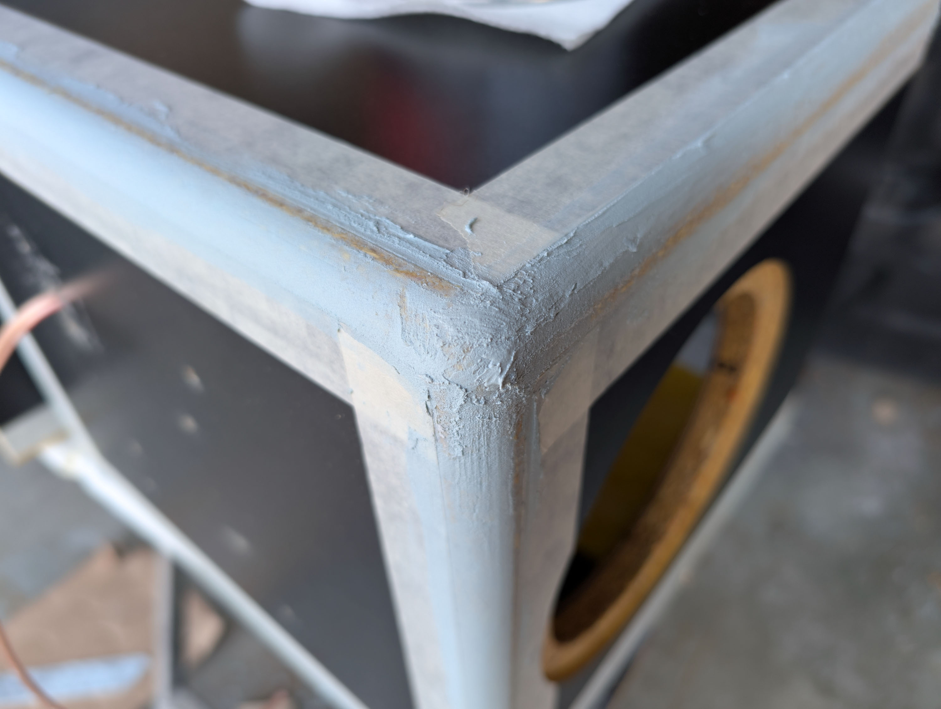
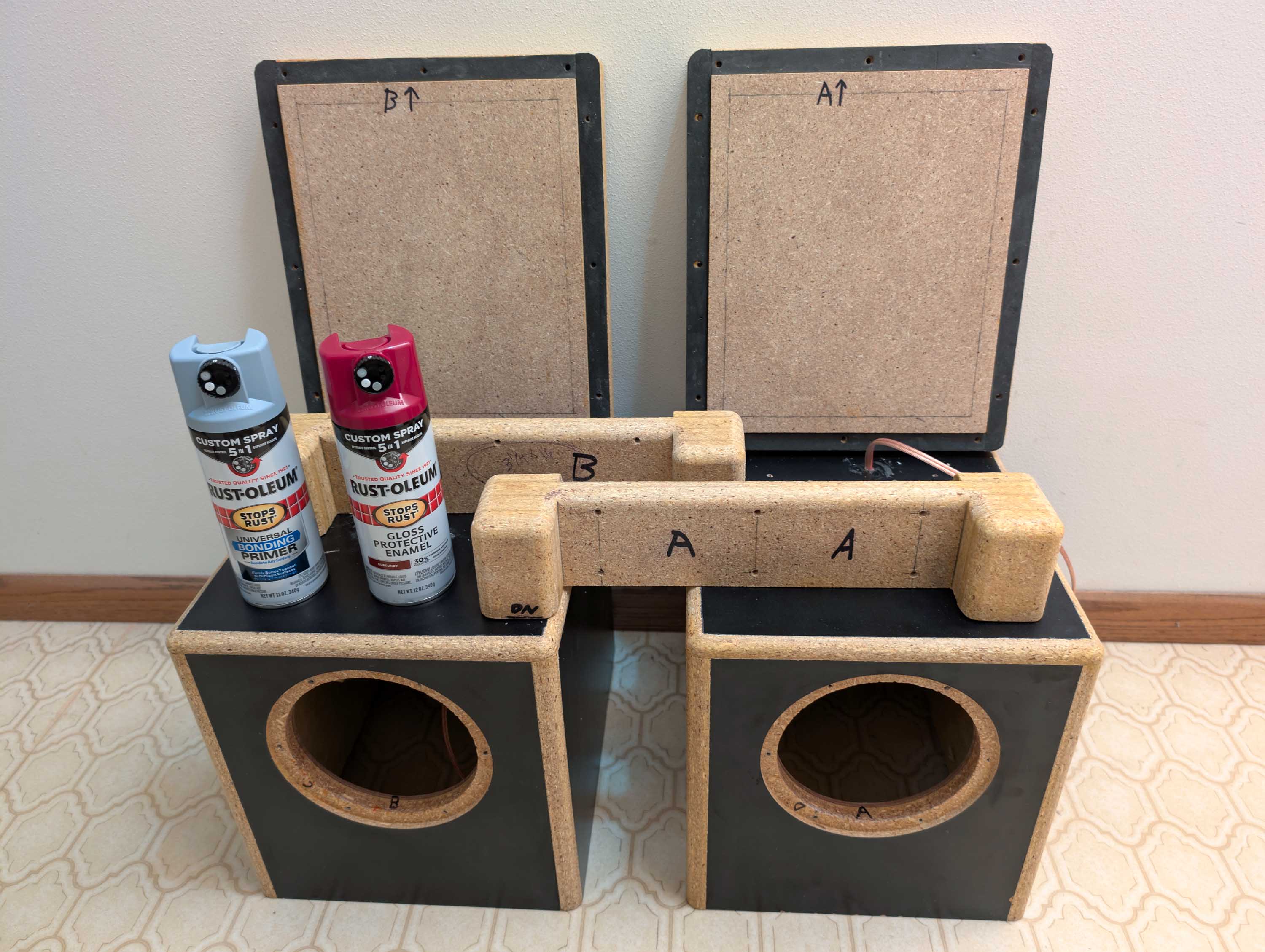
I’ve now taken this project as far as I can go when working indoors. The upper RD40 cabs are all wired up and ready to go. Next stage will involve moving out to the garage to complete the bondo filling, priming, and painting of the bass bin edges, bottom edges, and caster wheel assemblies. Going to try out the new fangled “5 in 1” rotating nozzle Rust-o-leum rattle cans. Universal gray bonding primer and gloss enamel burgundy. It is way too cold right now to work in my garage, so I’m putting this project on hold until we start getting some 55F+ days. In the mean time, I’m going to shift over to my Williamson tube amplifier project and work on that for a while instead.
4 Likes
Good information with the CSD