I have found Brad @ Jule Fidelity to be a class act and very organized as well - his attention to detail and packaging is top notch.
3 Likes
There’s a 3D printed speaker build that filled the walls with a mixture of PVA glue and plaster of paris.
1 Like
I saw this a while back! I think it’s an interesting technique and potentially worth investigating for another project. I do say another project though, I’ve done something similar with wood and polymer concrete and it was quite the messy affair - the linked video shows this is an issue with the PVA/PoP mixture as well. For these projects I’m trying to simplify the build process through extended design and prototyping processes.
That said, I’d really love to test all of these options someday. I’d need a fleet of 3D printers though to make all the required cabinets!
- PLA vs PETG vs ABS vs ABS GF vs Maybe PC?
- Gyroid vs several other infill types
- Infill percentages, say 10-50%
- Intra-panel damping - PoP vs Epoxy (if it doesn’t melt the cab) vs Epoxy Concrete vs TPU vs wood inserts vs ???
- Wood vs 3D printed (rigid and non-rigid) bracing vs ???
- Integrated CLD methods…
The list is probably much longer than this, but man would it be fun!
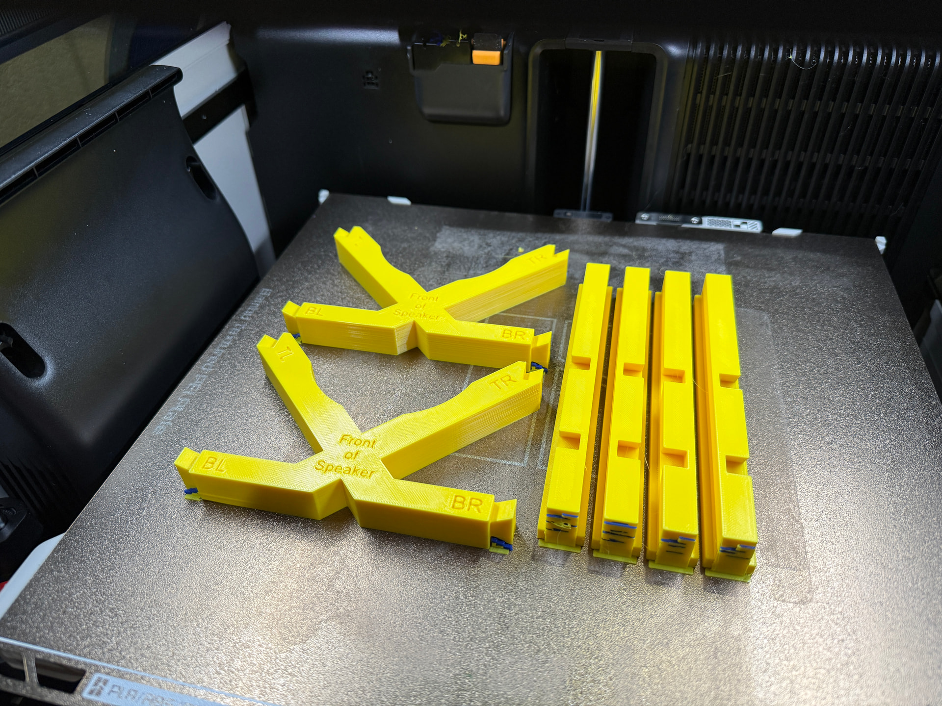
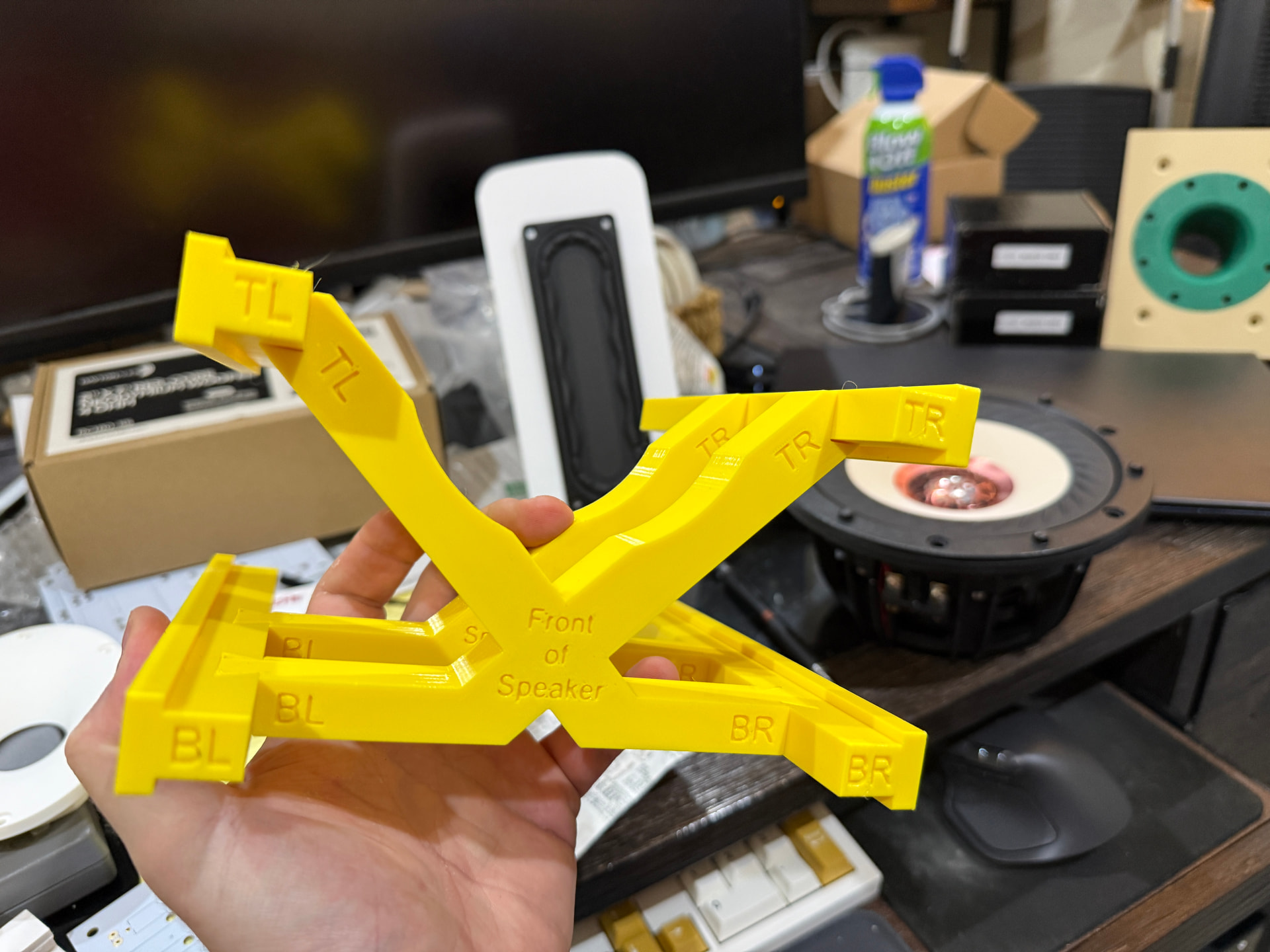
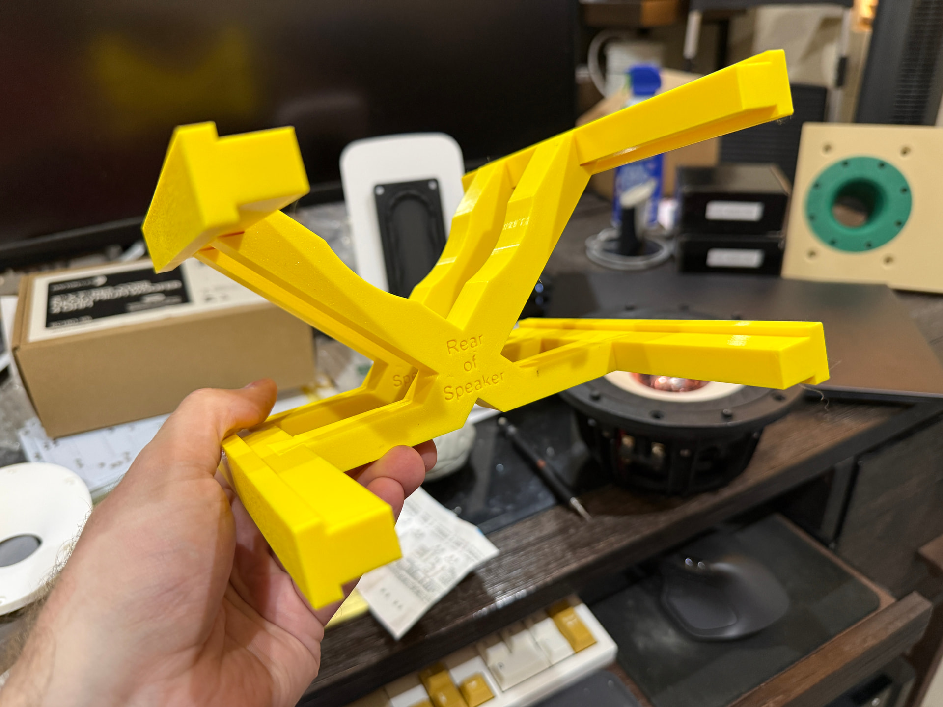
First upper brace is complete and I’m printing a second one…but I may replace the ‘x’ pieces with TPU.
4 Likes
I have always wanted to do so as well actually! I would certainly be down to help with that; take some of the 3D printing load off. I believe that @KenRhodes also has a 3D printer? Maybe we could all collaborate to print and test a bunch of materials, infills, etc. I have a Bambu H2S at work, and an Elegoo Carbon Centuri at home. Also access to an anechoic chamber at work…
I think one of the issues with testing is “HOW” do you actually test different cabinet materials and bracing. Most of what I see is very unconvincing - e.g., accelerometer tests with no correlation to the audibility of vibrations and resonances.
I’m going to experiment with low (15-20%) gyroid infill filled with epoxy resin (which should be much easier to work with than Plaster of Paris). But I have no idea how I would determine whether it is “good” or not, unless it is just obviously terrible.
I agree. I do wonder if distortion tests further away from the point source would be more telling if the cabinet is producing any audible frequencies. You’d need a quiet space outdoors at the very least though, or a decent sized anechoic chamber.
Careful with that epoxy @a4eaudio, even the deep pour stuff can warm up a fair amount. Are you planning on doing the whole thing in one go or just doing a certain amount of mixture and allowing it to cure between pours?
I’ll likely do it in 3 pours. I wanted to do 2 but there really is no reason to risk messing things up when I will be in absolutely no hurry.
Absolutely. That’s one thing I never really decided on. But an accelerometer on a panel may provide some information; the question is how would it translate to an entire speaker cabinet. Maybe starting with a correlation test of a full speaker cabinet versus a panel to see if there is a relationship between the two; in order to make testing different panels easier. Hm may talk to my coworker next week about this.
Anyway, didn’t mean to get off topic! May start a new thread sometime about this
Tentative testing plan is below.
Static test materials:
- PETG Baffle, Rear, Port, and Terminal Plate (6 wall loops, 25% gyroid infill each)
- Same woofer and tweeter between tests (tweeter just being a seal for the hole in the baffle, intent is to test woofer only unless I hear I should do otherwise from members here and elsewhere)
- TPU gasket for the tweeter (it otherwise has no gasket) and the stock ‘foam’ gasket for the woofer
- As an aside, the stock foam gasket is, IMO, not very good. The frame is also not flat (there are cavities in it), which leads me to believe the stock gasket material may not make a great seal. I may test TPU and neoprene gaskets on the final cabinet design, but I think most builders (especially new builders) would probably just use the stock foam.
- Ideally we’d use sorbothane, I think, but it’s a little pricey.
- Modern recommendations indicate using neoprene o-rings between the screw head and woofer frame may be of use as well, so my intent will be to do this. That said, if the woofer ‘sides’ are snug in the baffle I’m not sure there is a point to this. It should probably be ‘loose’ or ‘floating’.
- TPU Gaskets for Baffle, Rear, Port, and Terminal Plate
- As with the woofer, I may try testing neoprene gaskets on the final cabinet design.
- I’ll experiment with stuffing, but I’m not sure I want any for this test. Whatever the result I’ll use the same amount between tests. Open to thoughts here.
There are so many possible variables here that could (and maybe should) be tested, but I’ve narrowed it down to this for now. I have several other open speaker projects that this test will inform and I may evolve the testing for those based on these results.
Cabinets:
- PETG Cabinet (18mm sides, bottom, and top), 6 wall loops, 25% gyroid infill
- PETG Cabinet (18mm sides, bottom, and top), 6 wall loops, 10% gyroid infill
- If a significant difference is seen between the above, then: PETG Cabinet (18mm sides, bottom, and top), 6 wall loops, 15-20% gyroid infill
Bracing:
- No bracing (cabinet only, albeit with t-slots for bracing that may add rigidity compared to a cabinet without the t-slots)
- Rigid bracing bars in the t-slots (PETG, 6 wall loops, 25% gyroid infill) with TPU beams connecting them (the ‘X’ shape in my previous post)
- Rigid bracing bars in the t-slots with rigid beams connecting them (PETG, 6 wall loops, 25% gyroid infill)
I’m open to ideas on testing methodology, but I think this is the plan to keep things short and sweet:
- Woofer sweep, quasi-nearfield response and distortion measurement. Thought process here is that vibrating walls would influence woofer behavior. Ideally I could also do 1+ meter measurements but I’d either need a quiet place outdoors (I live by a reasonably busy street so…nope) or an anechoic chamber (also nope).
- [Idea from augerpro’s various threads around the web] Measurement sweep dead center on one side of the speaker, 1/2" distance from the side and gated to (hopefully) remove woofer response. I’ll need to reread his threads to confirm methodology. Thought process here is that if a panel vibrates it probably makes some amount of sound. Curious to know the amount of it.
Edit: And an impedance measurement, of course.
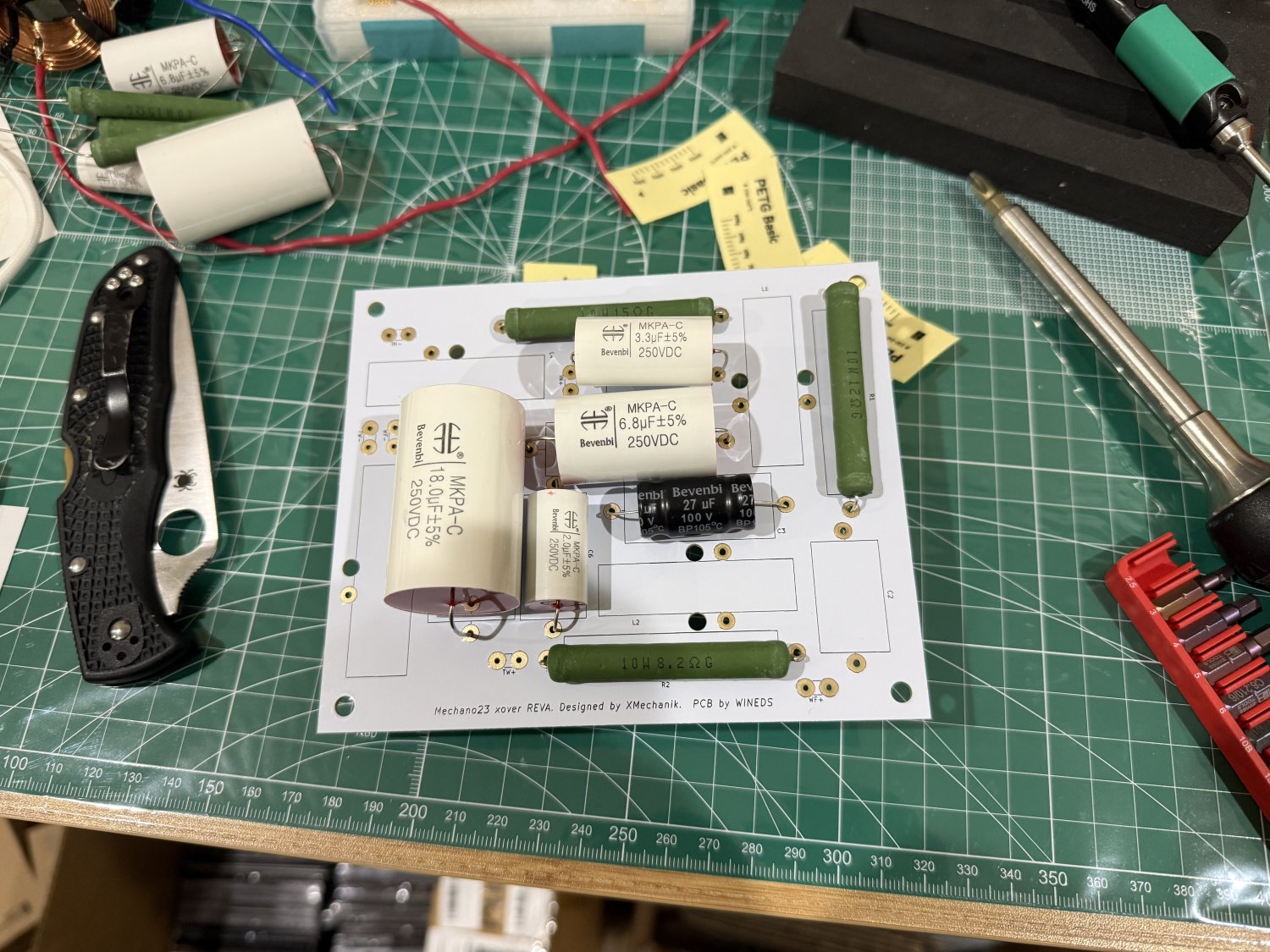
I received the rest of the crossover components yesterday and mocked up the Bevenbi caps from Cinergy and the Mundorf resistors from Madisound. They fit! Some of the caps are a little tight (I seem to recall the 3.3uf one being a bit ‘long’, as was the 18uf cap) but they’ll work.
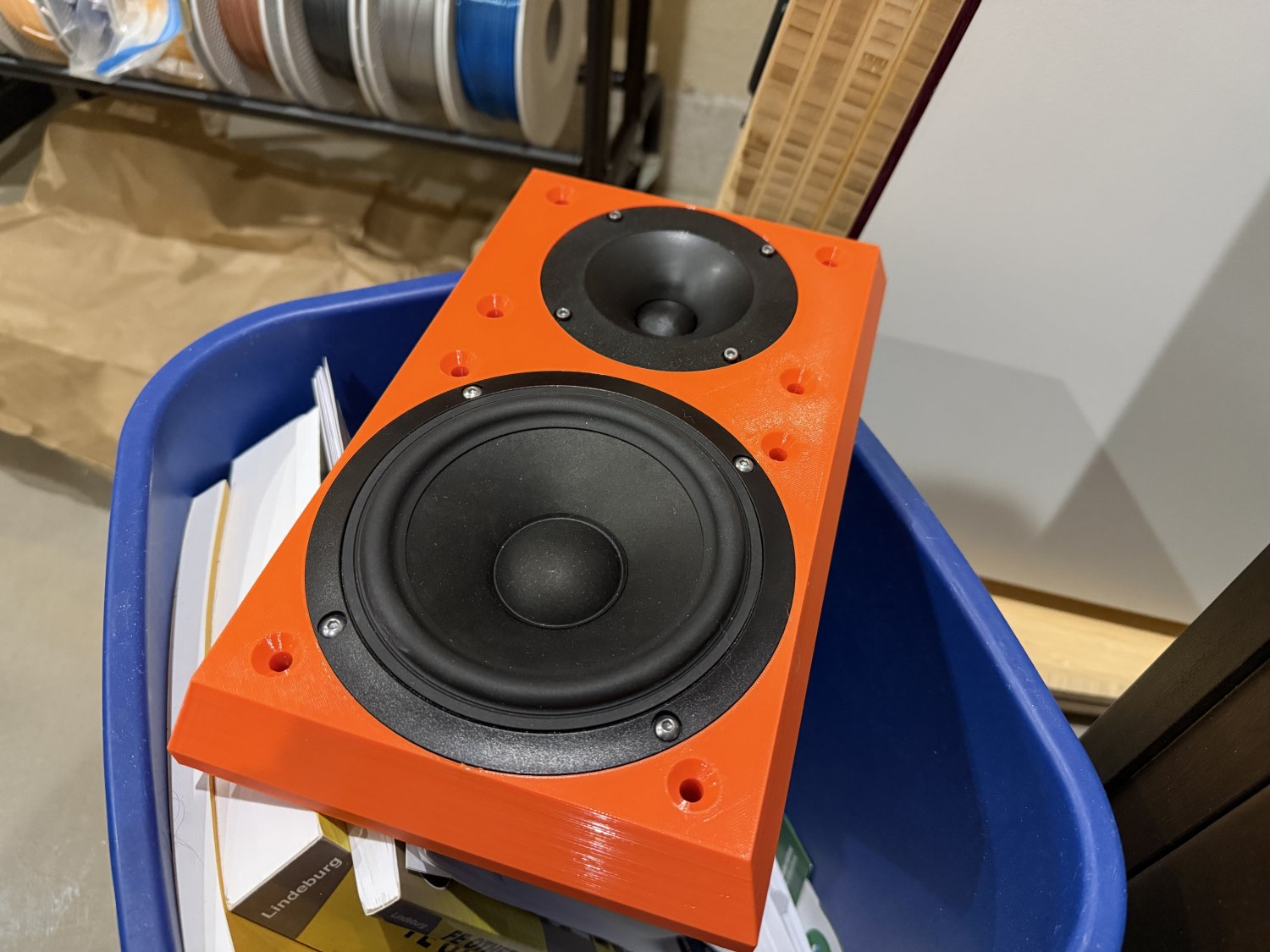
In other news I’m almost done with the prints I’ll use for testing. The baffle was straightforward since I’ll use the chamfered one I had previously designed but only printed as a test run in PLA. This one is PETG, 6 wall loops, 25% gyroid infill. Woofer fitment is a little tighter than I’d like and I’m waiting on final hardware, but this is it. Printed face-up, this printed with no supports required. I’m not a huge fan of the top surface finish, the ‘final’ baffle might be printed face down to get some texture, though that would require some supports to do.
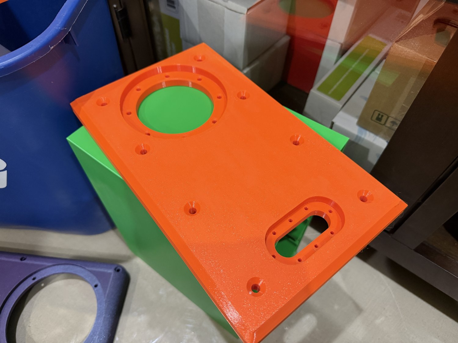
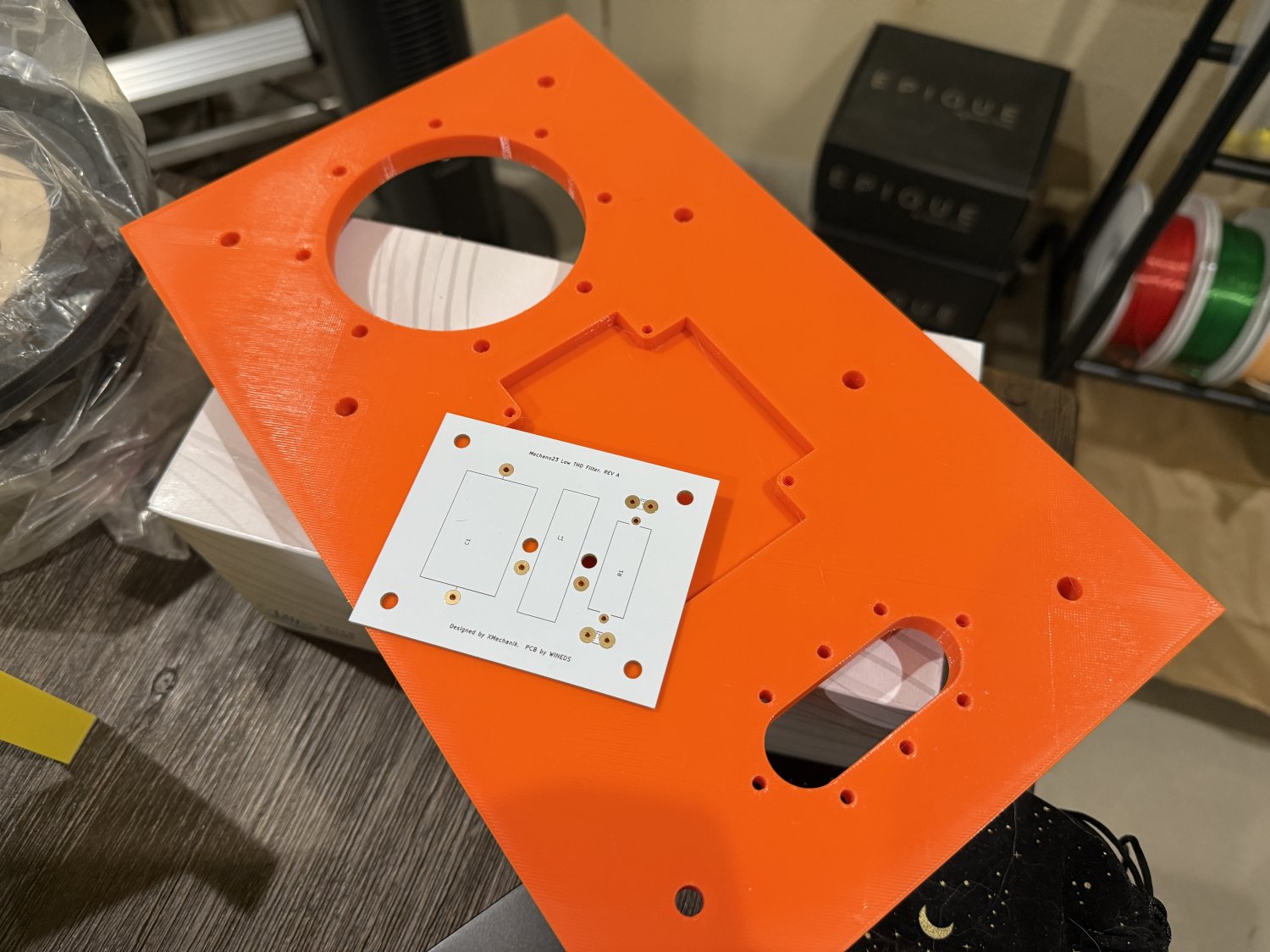
Rear of the cabinet was slightly redesigned and printed face-down to test the aforementioned textured finish. No matter which way this was printed it would require supports so it seemed a good test subject. I chamfered the corners slightly to break up the hard edges a bit (this is purely for aesthetics) and added a place on the ‘inside’ for installation of the THD board. As with the baffle, this is PETG with 6 wall loops and 25% gyroid infill.
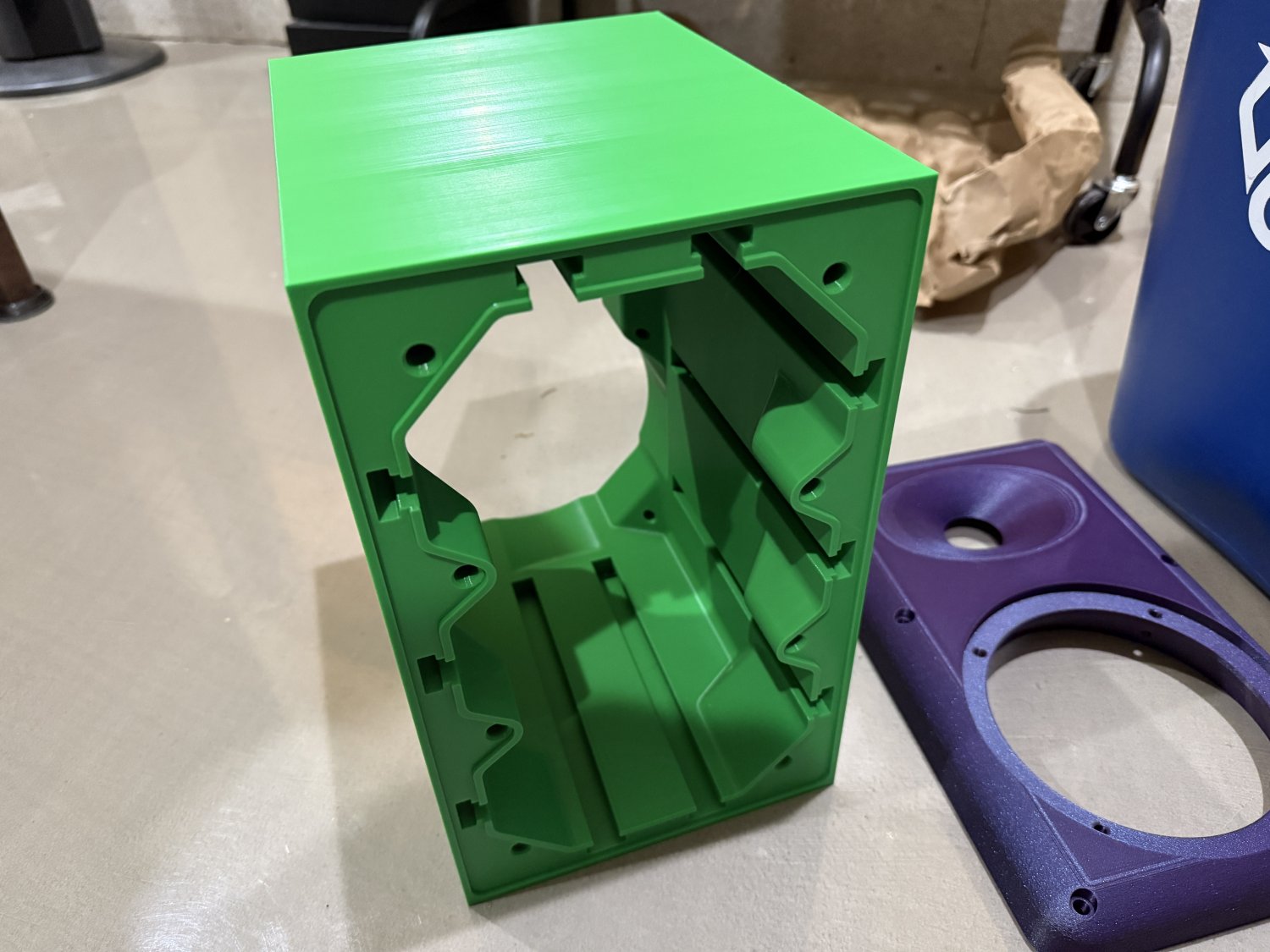
Finally, the first cabinet wrapped up after nearly 3.5 days and 2.2kg of filament. Also PETG, 6 wall loops and 25% gyroid infill. I started the 10% version immediately (it’ll take about 2 days and 1.7kg of filament, IIRC).
Front:
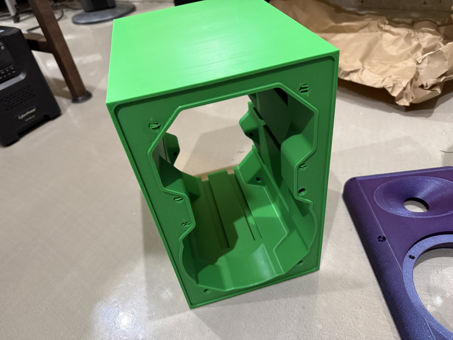
Back:
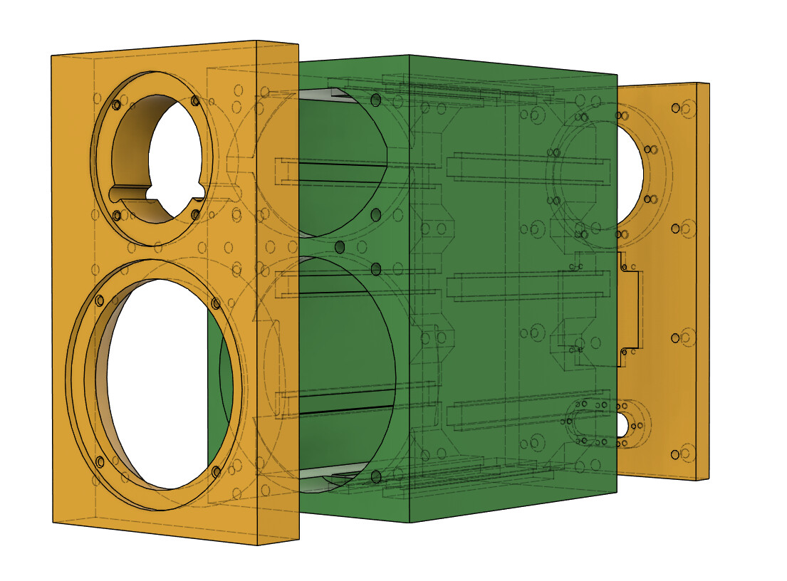
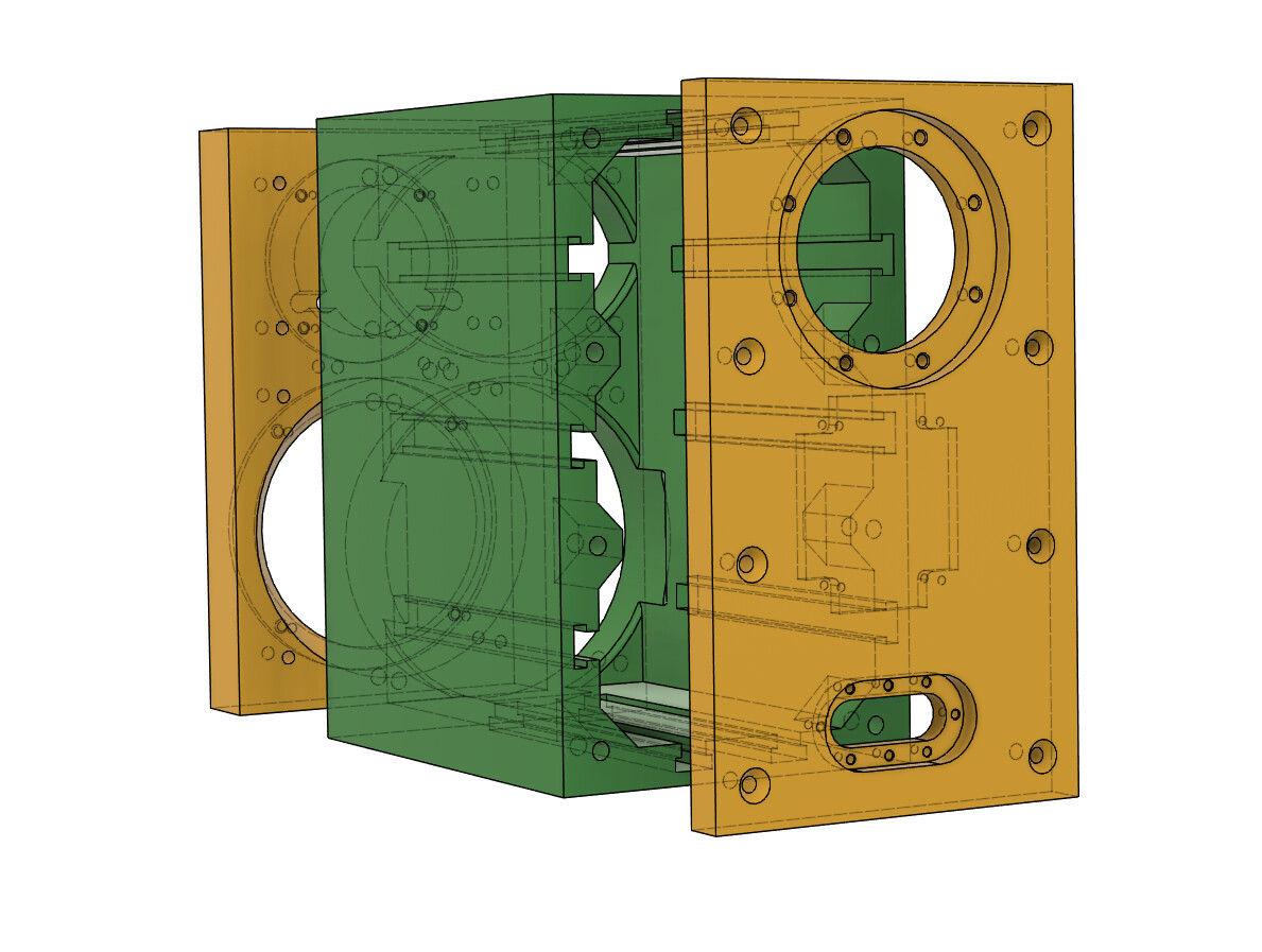
I have started redesigning the cab, baffle, and rear a bit to simplify the prints. First, someone mentioned earlier that some might prefer a cleaner look on the front, and since the rear is removable too we could just run bolt through the backside of the baffle to attach it to the cab. I initially disagreed because I like the look of hardware, but I’m now thinking a bit differently. This also impacts the spacing of the bolts on the rear since they originally matched the front - this is no longer a requirement so they can be spaced out further. I also added a cross-brace to the front because the box prints face down, so why not (I’m still thinking about making this brace removable, similar to the other braces). Lastly, I removed the groove for the TPU seals, at least temporarily, if not permanently. I’m thinking about these junctions a lot and may introduce some new pieces. We shall see.
By the by, I’ll be making several baffles available. Baseline (as shown below), roundovers on vertical edges, chamfers on all edges, and faceted vertical edges with chamfers on top/bottom. Just want to give builders a choice. I will try to take measurements of each eventually.
4 Likes
Killing it
2 Likes
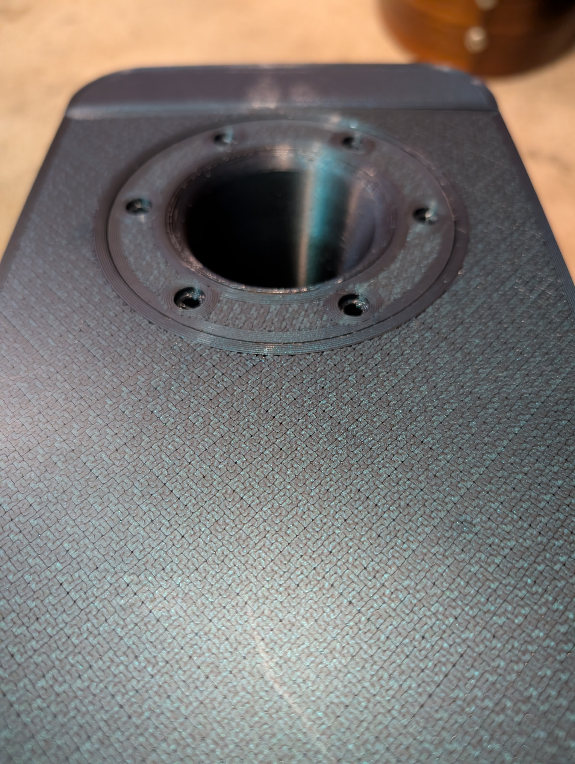
I think figuring out how to print such that you can just take it off the print bed and use it is still quite a challenge, even with how good the printers have become. The best I have done so far is using fuzzy skin, which works great for waveguides, but it increases the print time a lot, which in you case could be quite extreme. I have found examples (but not speaker examples) of wet-sanding PETG to an almost piano gloss finish, which I am going to experiment with.
The other thing that I tried which worked “okay” is to print face down on the smooth PEI plate and set a “Bottom surface pattern”. It may work just as good printing face up, using “top surface pattern”. I only did it for the BACK of the cabinet, and although I could probably get it to work by printing sides panels separately, it wouldn’t work for the baffle with chamfers or roundovers. But here is an example of the back of the cabinet with a “Hilbert curve” bottom surface pattern. There are 8 different patterns, so it would be easy to print a bunch of 2" x 2" rectangles face down and face up with the different patterns to see how they work. Its not going to work for your single big print, but if you haven’t messed around with the patterned surfaces I thought I’d mention it, as it might give you some more ideas.
3 Likes
I have played with some of the patterns, including the hilbert curve! I’m not sure what I’ll end up with, but I could opt to just, like, minimize flat surfaces altogether and try my hand at sanding and polishing too.
This minimizes things a bit…
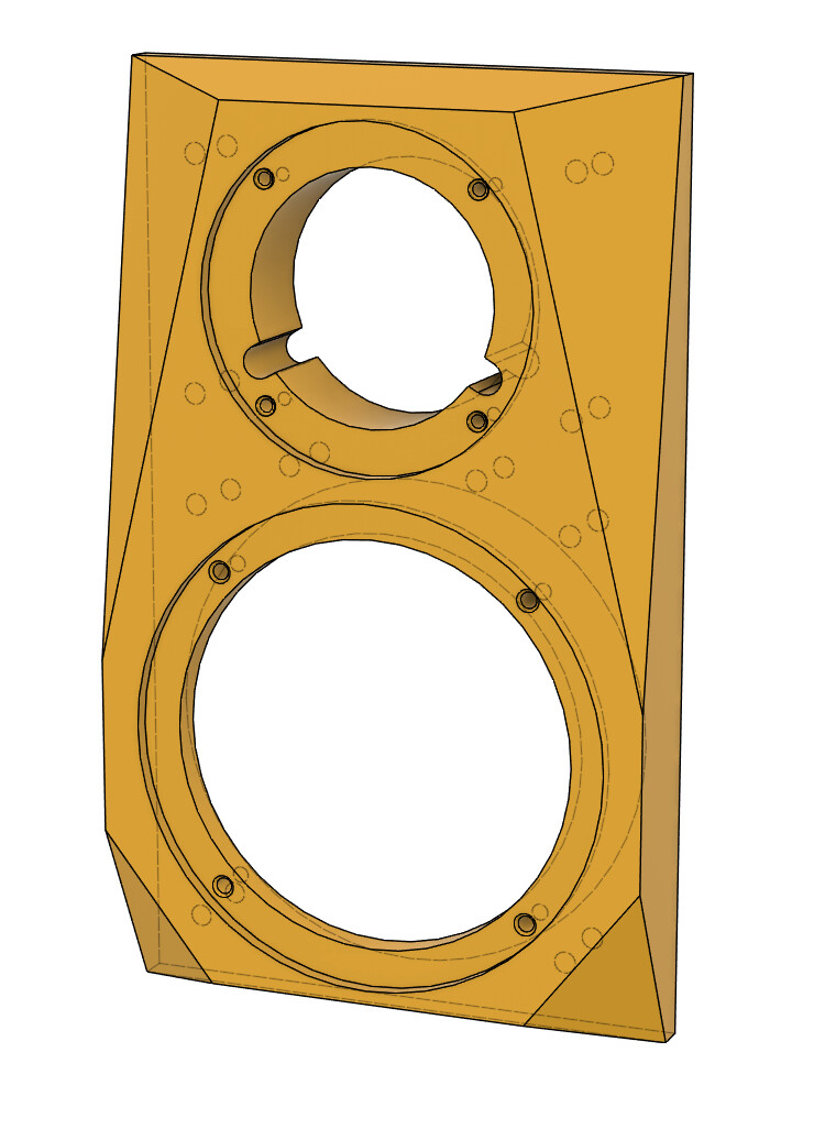
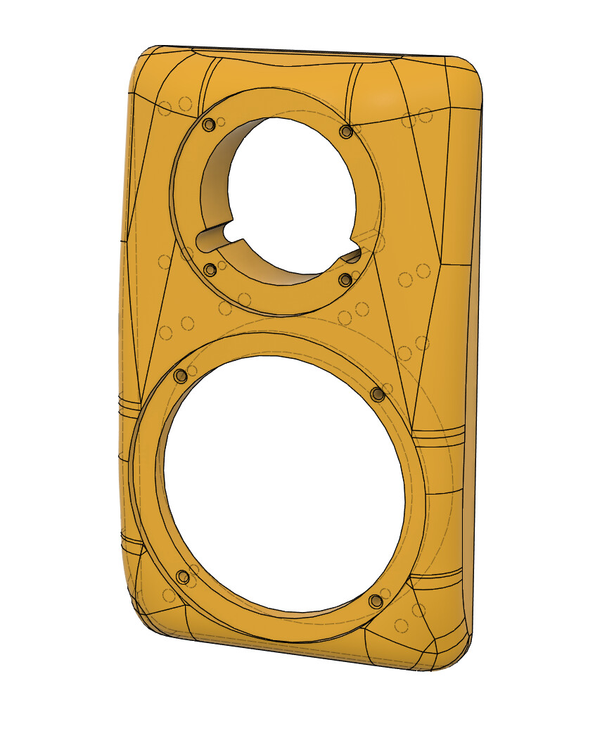
Maybe better viewed this way.
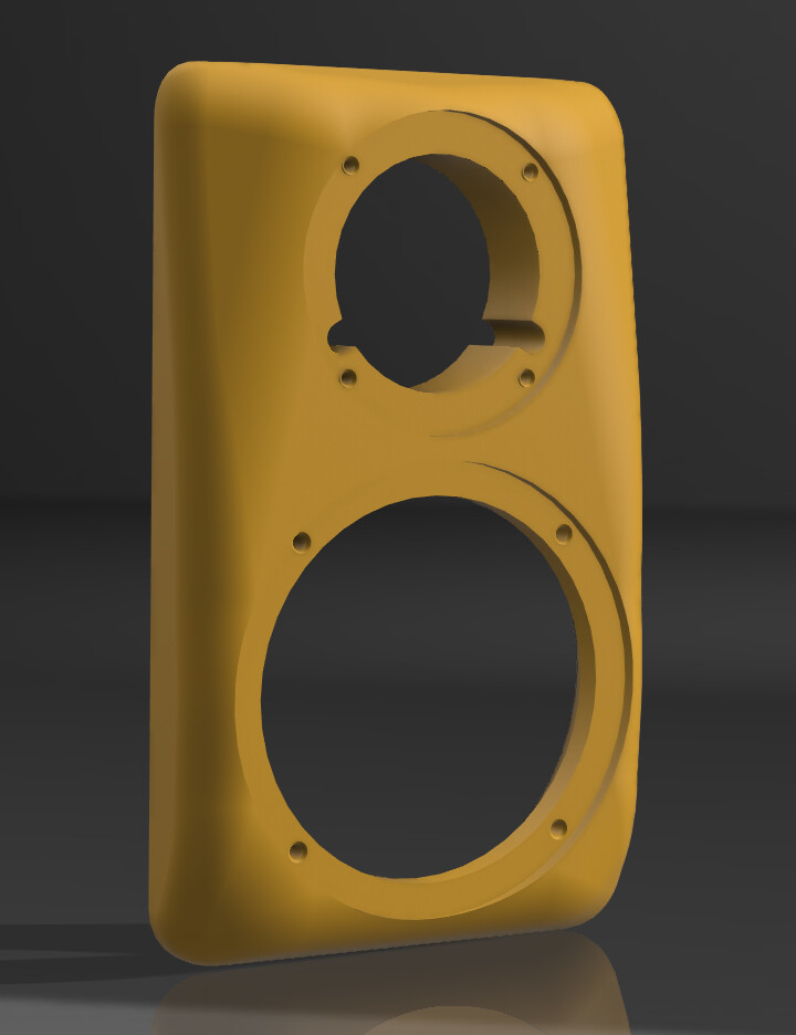
3 Likes
That last design with the rounded-facets is pretty cool!!
Thanks! I’m a CAD novice (at best!) so implementing those facets and curves took WAY longer than it should have. I don’t know the ‘right’ way to do them but I think I have a way that works for me. Might be able to refine that into something that works well with augerpro’s waveguides.
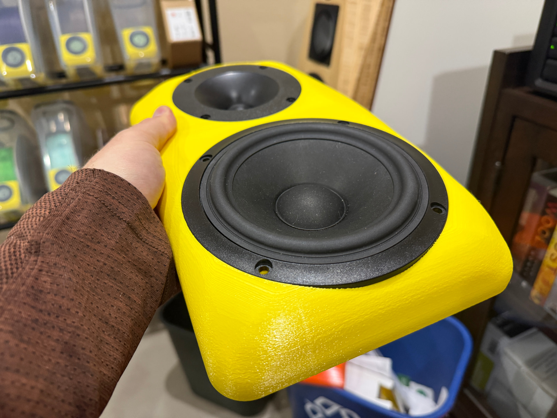
Edit: I decided to print that one with both fuzzy skin and ironing on top. Went low infill and wall loops to keep it reasonably quick, just trying a few things out to see what can be changed.
2 Likes
Perhaps as expected, the ironing doesn’t look great since the ‘top’ flat surface was pretty small. That said, the small portion that was done looks pretty darn nice. Likewise, the fuzzy skin looks nice too. It’s the transition between the two that is a bit questionable…I feel something like this should really be sanded.
With the exception of the bottom lip of the woofer protruding a bit, these turned out really well! Even that small detail doesn’t really bother me.
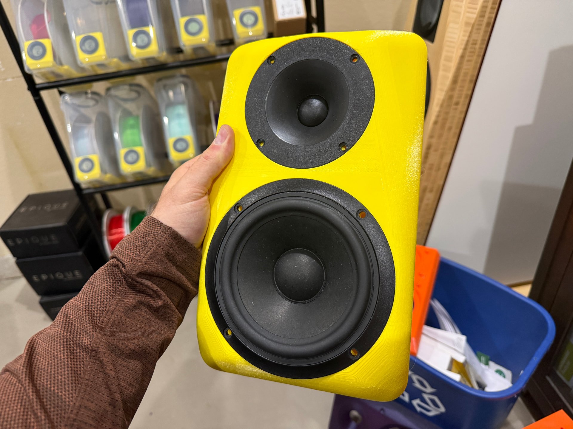
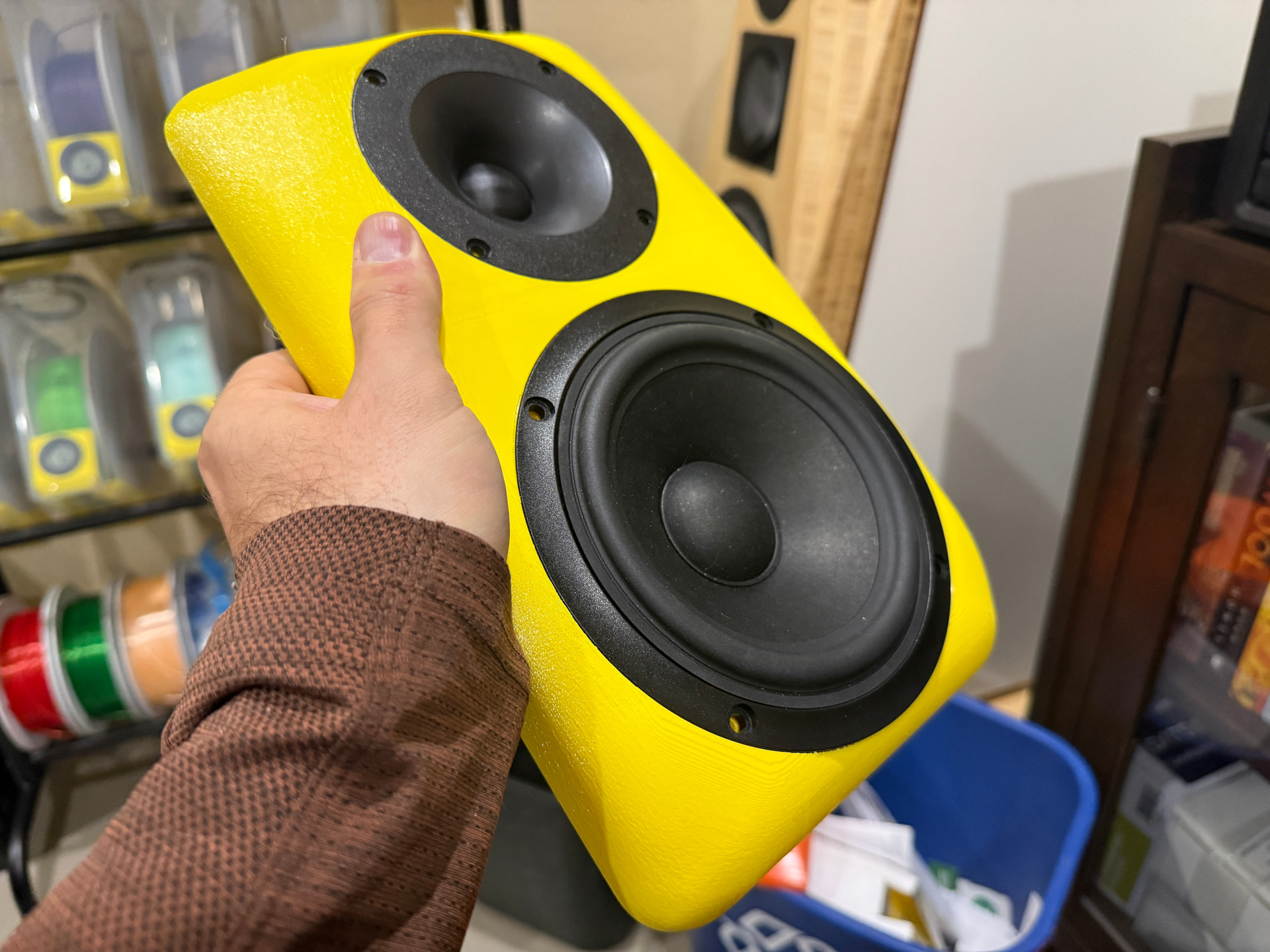
8 Likes
That looks fantastic!
Very nice prototype.
I have absolutely no idea what the costs are for such work, but if it isn’t too crazy the on-demand kit production could be pretty substantial for an entity with the templates and hardware. Since it hasn’t been done yet I’m guessing this doesn’t approach the woodworking options financially.
Any thoughts?
1 Like
Thank you all!
I think, provided one has an appropriate CNC, Baltic birch ply (or MDF) would be more economical than a plastic one. I don’t think it would have a performance advantage really, given the small size of the baffles we’re talking about. The CNC would probably complete a single baffle in a couple hours and wouldn’t require much sanding. A quality 3D printed baffle would probably take ~12 hours apiece and require sanding, though I don’t know how hard that is at this time.
I think the only real advantages the 3D printed baffle has would be color options (not a big deal since you could paint a wood baffle) and stability in various temperatures/humidities (possibly a big deal if one were to sell the baffles and ship them across the nation).
I suppose you can also just set and print these overnight without needing to supervise. Probably don’t want to do that with a CNC.
For the record, this one has only 10% infill and 2 wall loops and took 10 hours to print. The filament cost was under $3 (~270g used of a 1kg roll, ~$10 per roll). Maintenance cost is cheaper yet, at least based on my use over the last year. Until testing says otherwise, I’d probably increase to at least 25% infill and 6 walls to ensure appropriate stiffness on a ‘real’ baffle. Top layer I might increase depending on how much sanding would be required, but I imagine the standard 6 layer top/bottom could be sufficient as-is. I’ll try on this prototype and see what happens when I get a chance.
Anyway, if someone wants to try such a baffle but doesn’t have a printer I’m happy to make some for you. Given the size of my printers and the methods @a4eaudio has mentioned previously, I imagine I could do most two way bookshelves for sure, possibly even one that uses an 8+ inch woofer. I can print fairly tall actually (almost 14") and the diagonal is 16" or so? So I guess that’d be the absolute limit. Adding an augerpro waveguide isn’t terribly difficult either, so I’ll be playing with that for sure on the SB STAC + MAC-05 system.
5 Likes