I’ve been seeing of people use UV resin to finish 3d printed parts, its thick like epoxy you apply it and hit it with the UV light and it has a glossy finish that hides layer lines pretty well. Its not a huge investment to try it either. UV resin is like 20 bucks and the light is another 20-40 and you can tint it or get colored versions too.
3 Likes
Do I need a UV light or can I just leave it outside in the Southern Nevada sunlight for a couple seconds? Let’s find out!
Seriously though, that is very interesting. I’ll need to look into that.
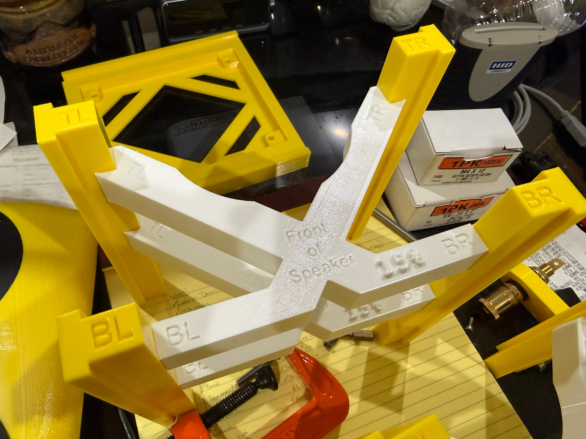
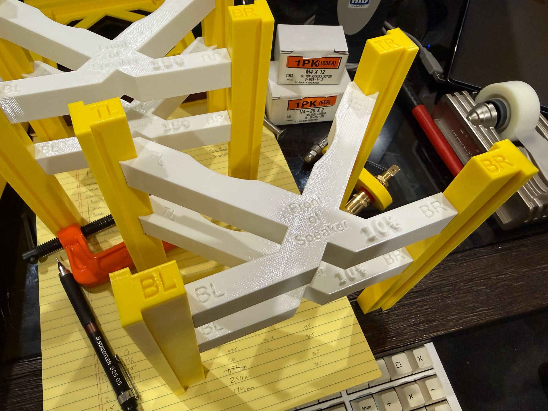
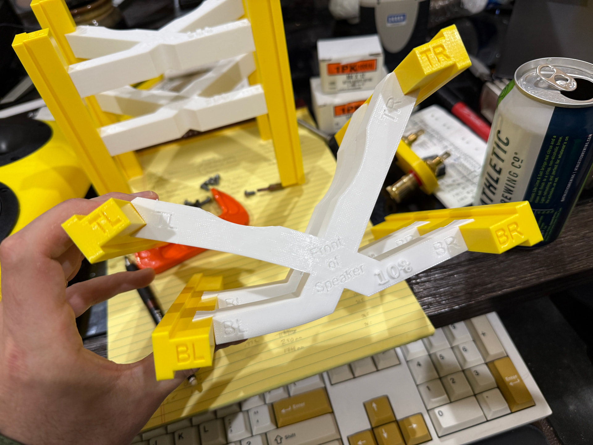
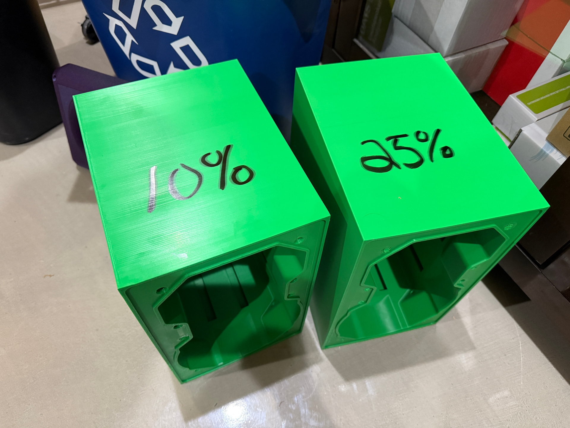
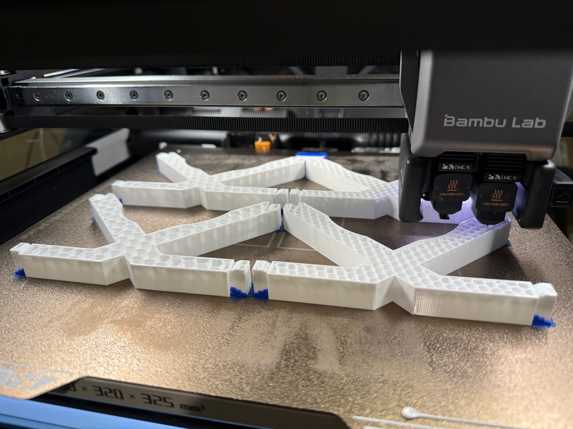
First prints of the flexi-braces I’ll test. I went with 10% and 15% honeycomb infill for these. I’m not sure the ‘top’ of the brace would offer much in the way of damping as currently designed but the lower suction should (maybe). I can tell the difference between them but I have no idea what would be ‘good’. I think I might go ahead and make 20% at least…maybe 25% too. This is 90A TPU by the way, so there are both softer and firmer types available. I don’t think going softer would be beneficial, but 95A might be interesting and I think I have a little left from another project. Both test boxes are done as well, so I’m almost ready for some numbers!
1 Like
Question: Since I’m testing these cabinets moreso than the woofers (i.e. I’m not planning on using the crossover or anything)…should I install a cap on the port hole instead of using the port to seal up the enclosure? Or even just make a solid rear piece for testing purposes? Or should I keep the port so the enclosure is ‘as designed’ in so much as volume and tuning and such?
I’m just wondering if the sealed version would help (or hurt) the amount of energy put into the cabinet walls. I would think the sealed version would impart more energy but I’m far from an expert.
I could, of course, test both. A cap would only take an hour or two to model and print.
I think around tuning the majority of the energy escapes through the port, but otherwise it acts as a sealed system so I don’t see any reason to plug the port.
2 Likes
Above tuning, just as much energy going on.
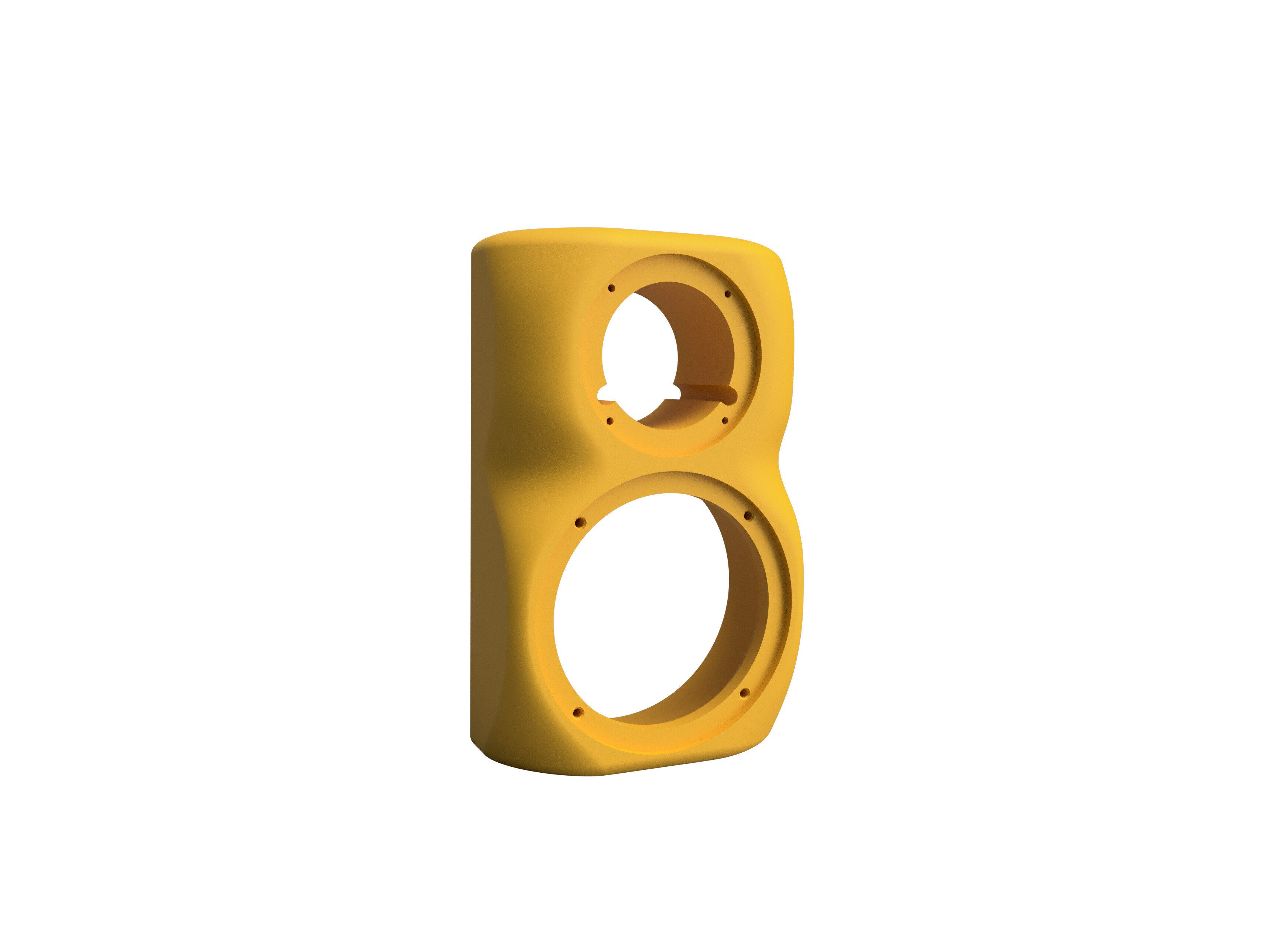
I’m wondering if something shaped like this is worth looking into. It requires a much thicker baffle to do and I’m a little concerned about the area between the tweeter and woofer. It is, however, a bit easier to replicate in CAD than the first ‘curvy’ baffle shown. This basically blends several curves of varying dimensions together, but fusion does not seem to allow me to do this while also making the curves asymmetrical, which is what I actually wanted to do. It’s either one or the other. Need to research this a bit.
Edit:
Since the intent is to 3D print the boxes I’ve been considering not-rectangular options for the cabinet and rear as well. I would like to do this for my own designs;I don’t really intend to change much on the Mechano23 since that could result in crossover changes.
Edit 2:
I’m also considering non-flat top and bottom bits.
2 Likes
This baffle shape looks very similar to my “SideTowers” build (pic & link below). I was able to significantly improve the polar response by molding the shape of the baffle around the tweeter and woofer into very smooth and large radius curved sections. Then I covered the mortite with 1/16" thick foam rubber to make it look better. As you print baffles, my advise would be to mount the drivers as you go along and then run polars of each print to see which shape produces the smoothest on and off-axis response.
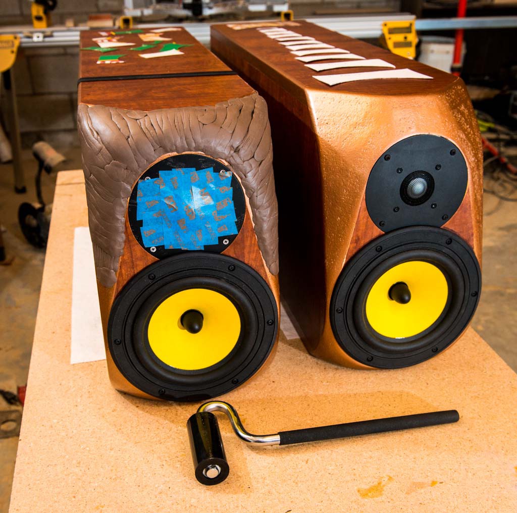
https://techtalk.parts-express.com/forum/tech-talk-forum/1393579-the-sidetowers-an-f6-corundum-build
2 Likes
I remember seeing this project a while ago, loved it then, love it now!
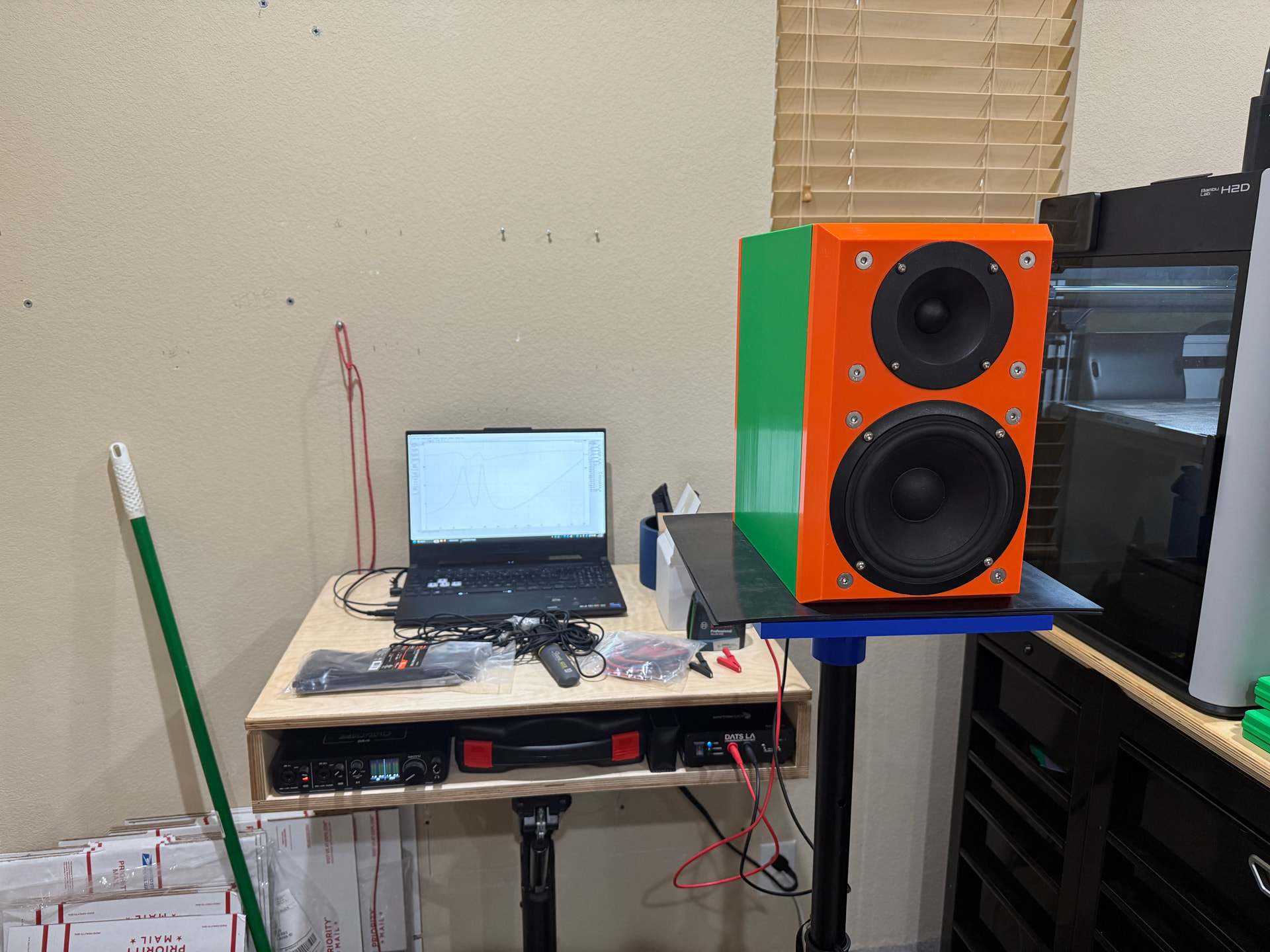
First test sample (10% infill box) is assembled.
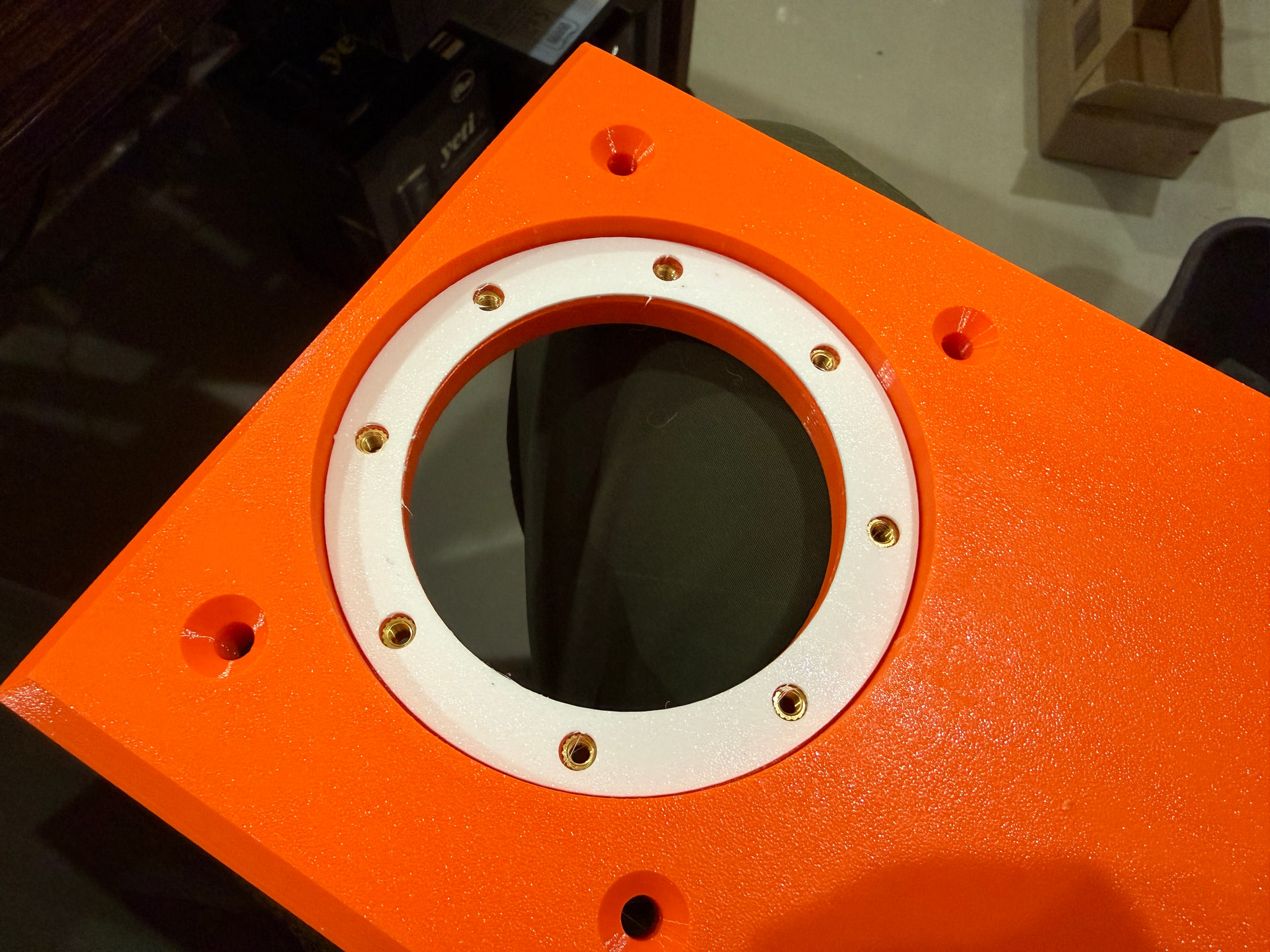
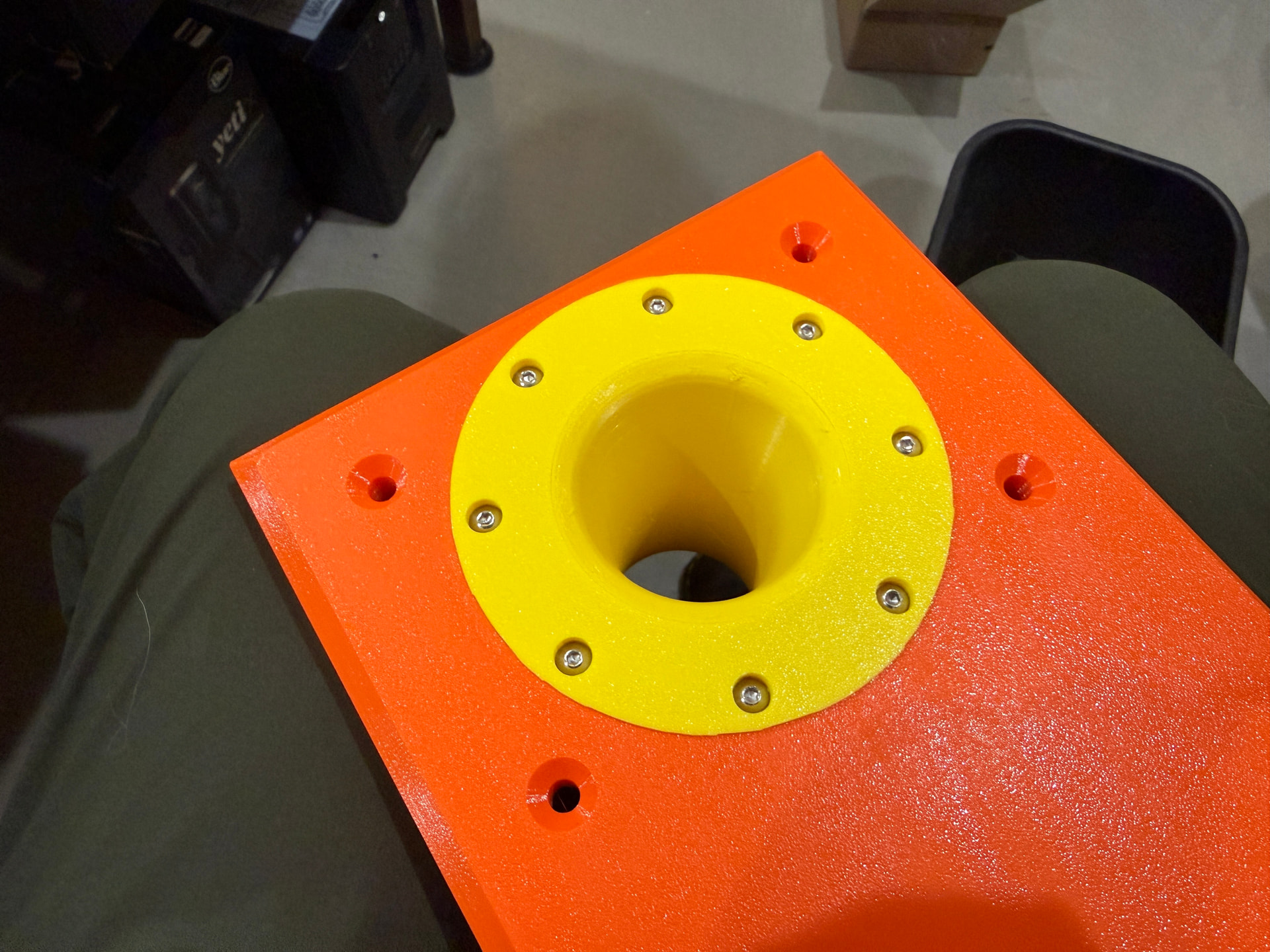
I purchased a heat insert press to ensure I was installing them correctly. There are several models that I could have printed and built but none that I found were large enough to handle the full thickness of the cabinet. Fortunately, these aren’t particularly expensive.
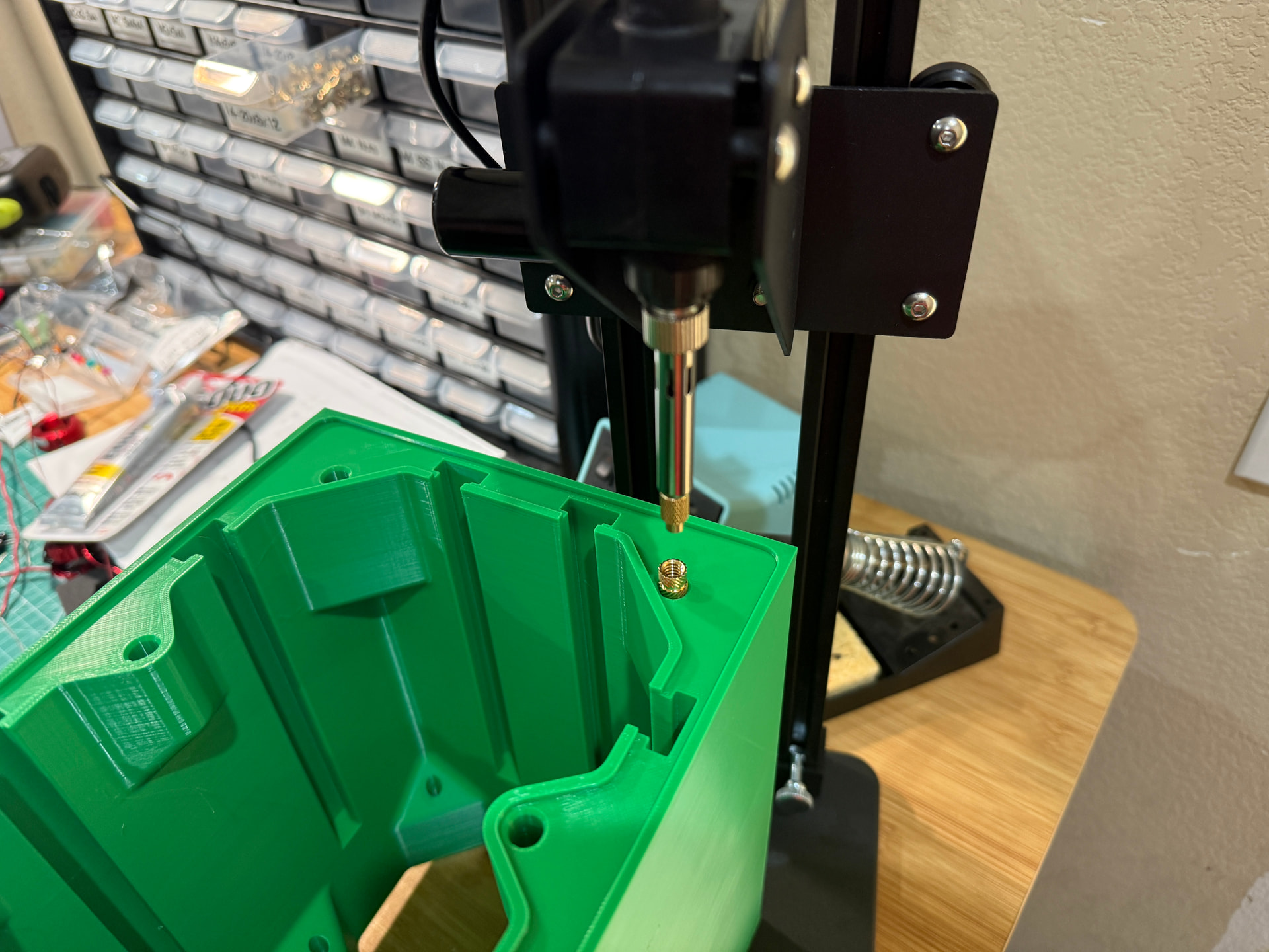
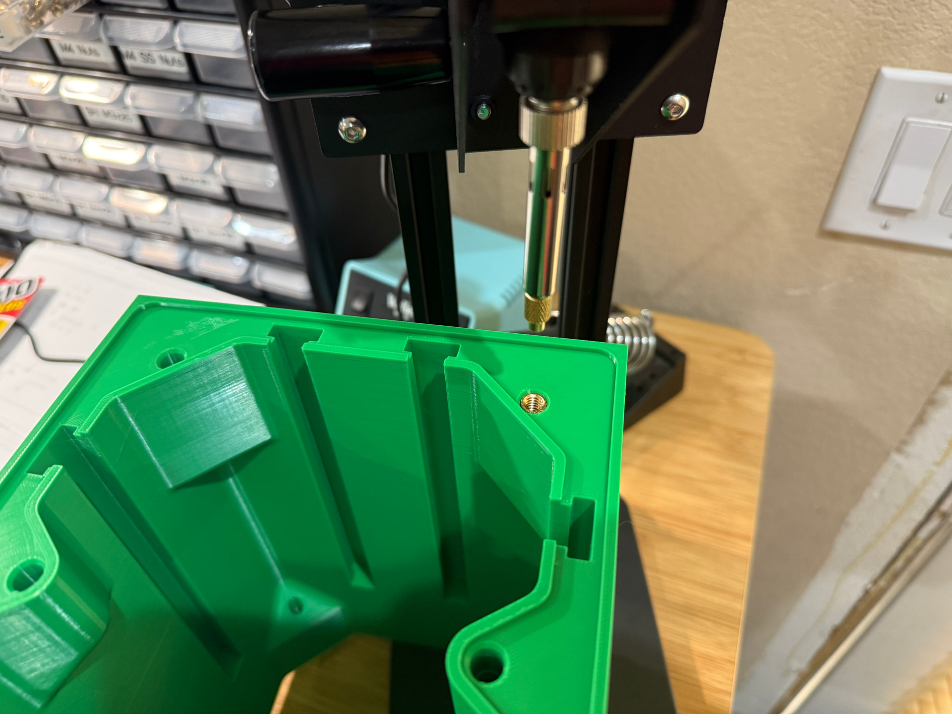
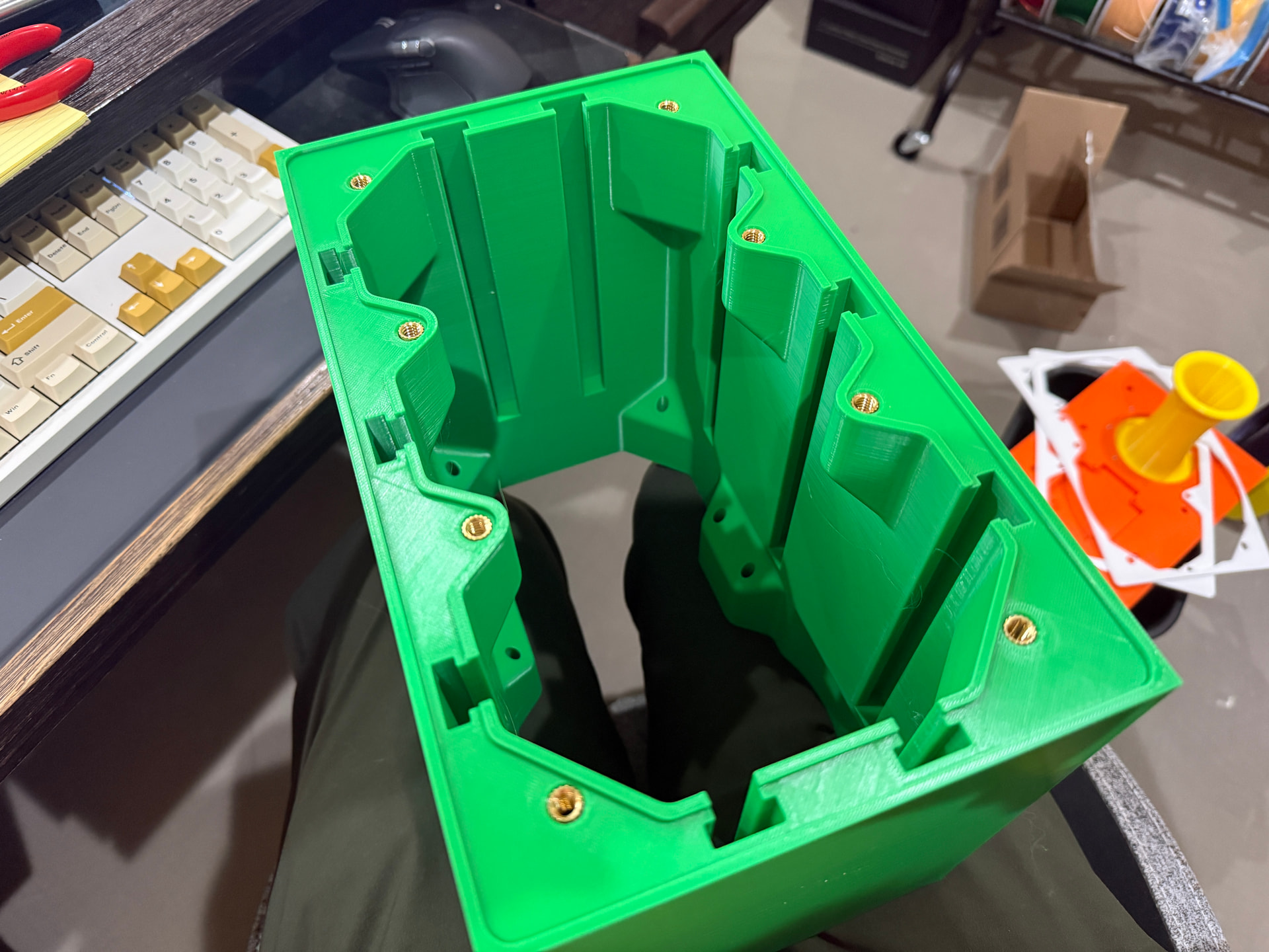
The TPU gaskets seem to work pretty well but I’m not sure how to test the seal.
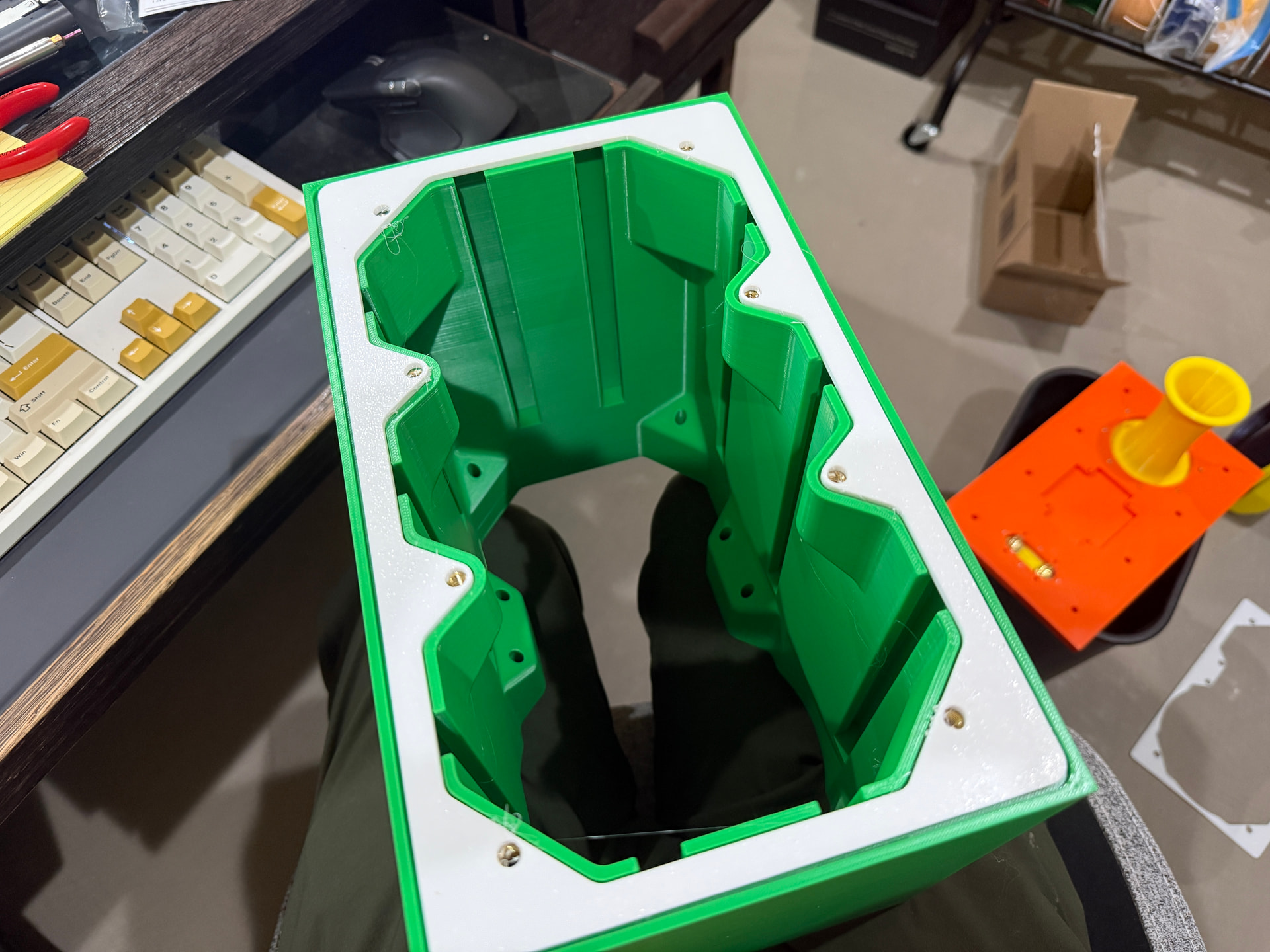
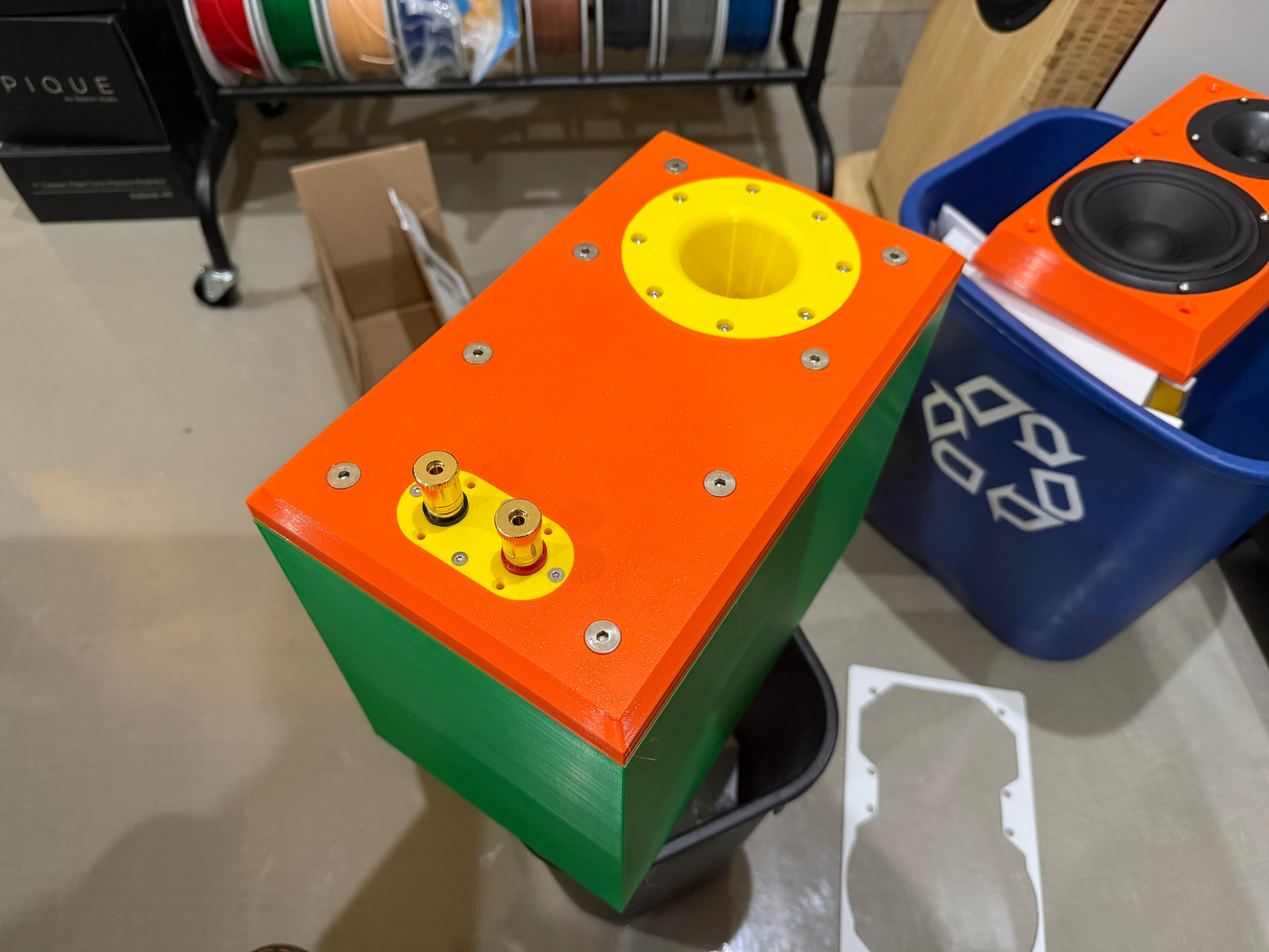
For these tests I was not planning on putting any stuffing in the box. This first one also has no bracing in it.
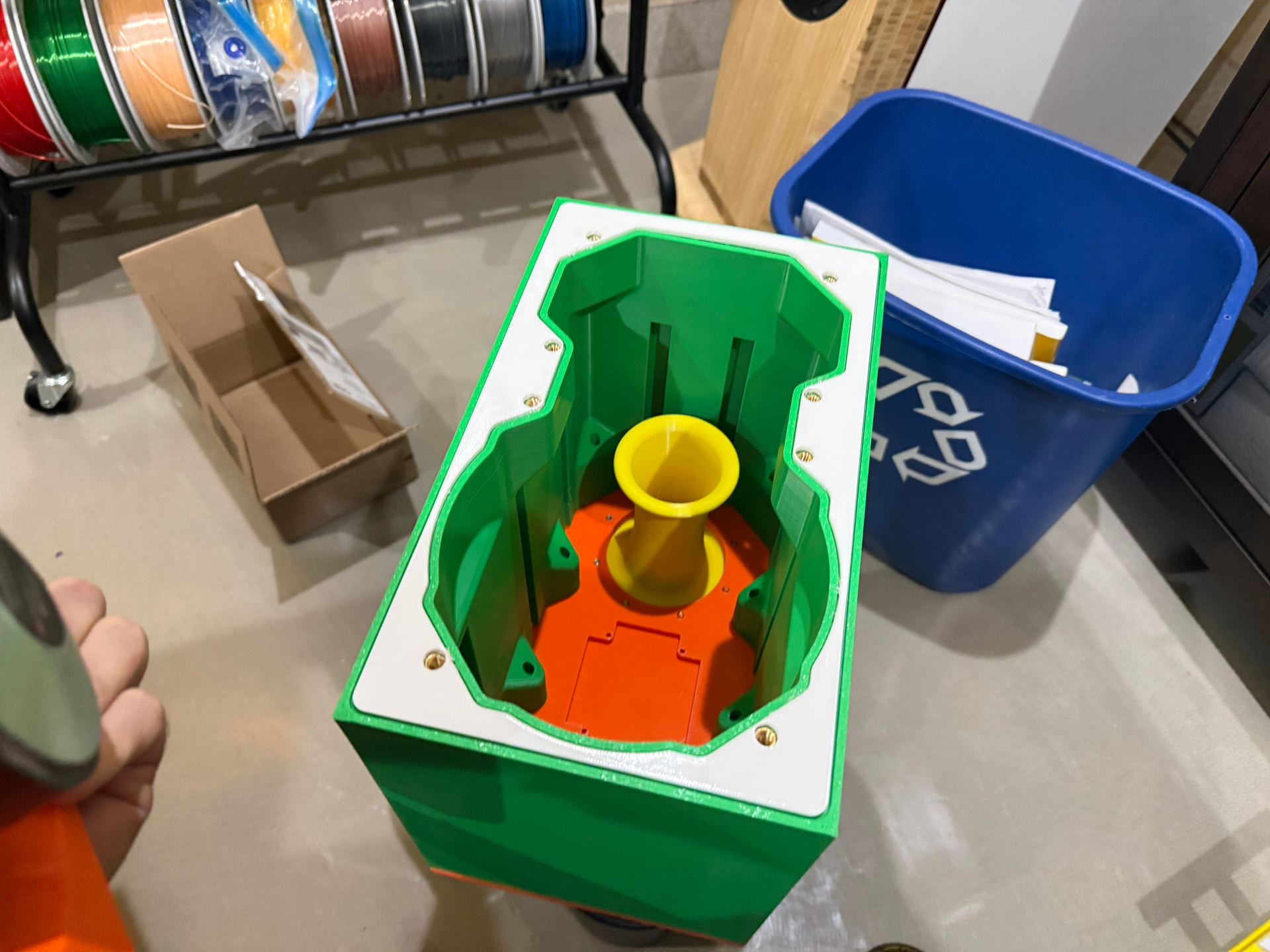
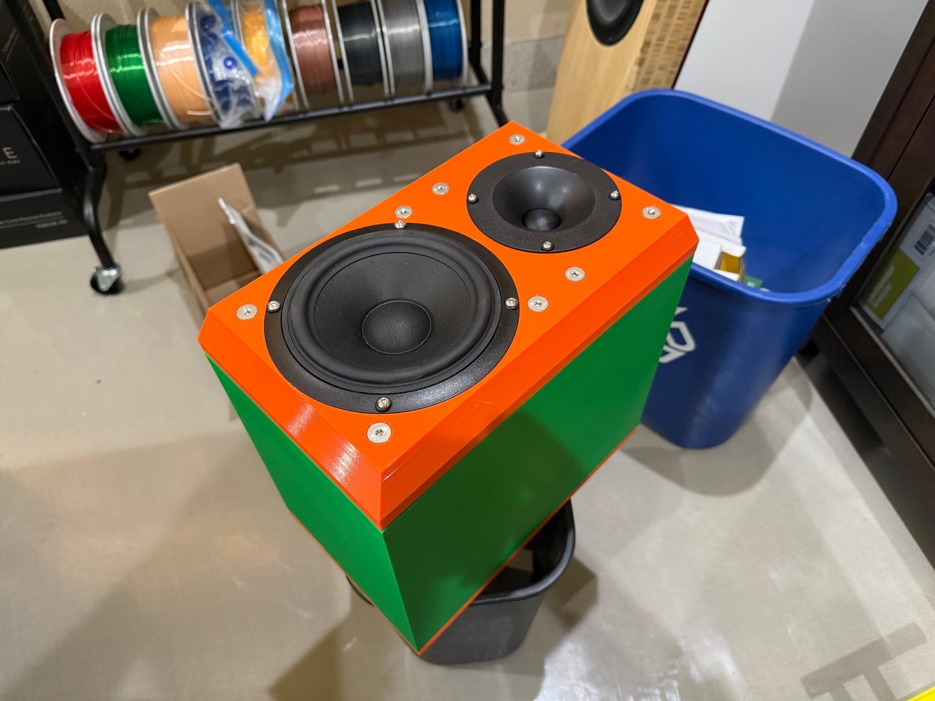
I did not have a great way of supporting a speaker for testing, so I got this inexpensive Pyle speaker stand. The stands that had platforms on them were pricier (sometimes a lot pricier) and this one is designed for pro speakers with 35mm receptacles in the bottom. So I just printed my own platform and set some neoprene sheet on top of it for a little isolation. I’ll need to make a different platform with the receptacle at the edge for taking off-axis measurements, but for this one it’s just centered.
2 Likes
I have to work around my air conditioner (it’s loud) which is kind of tough after noon so I’ll try more tomorrow. I did do an impedance sweep though and…well it works? I want to say I tried tuning for 55 Hz with the optimized port so I’m a little on the high side there, but that’s not wholly unexpected. Not a big deal, especially since at least some bracing, stuffing, and the crossover will change the volume a bit.
I did noticed two little bumps in the plot at ~280 Hz and ~680 Hz. Could be a cabinet resonance or maybe a standing wave? Open to ideas, I am NOT experienced in this.
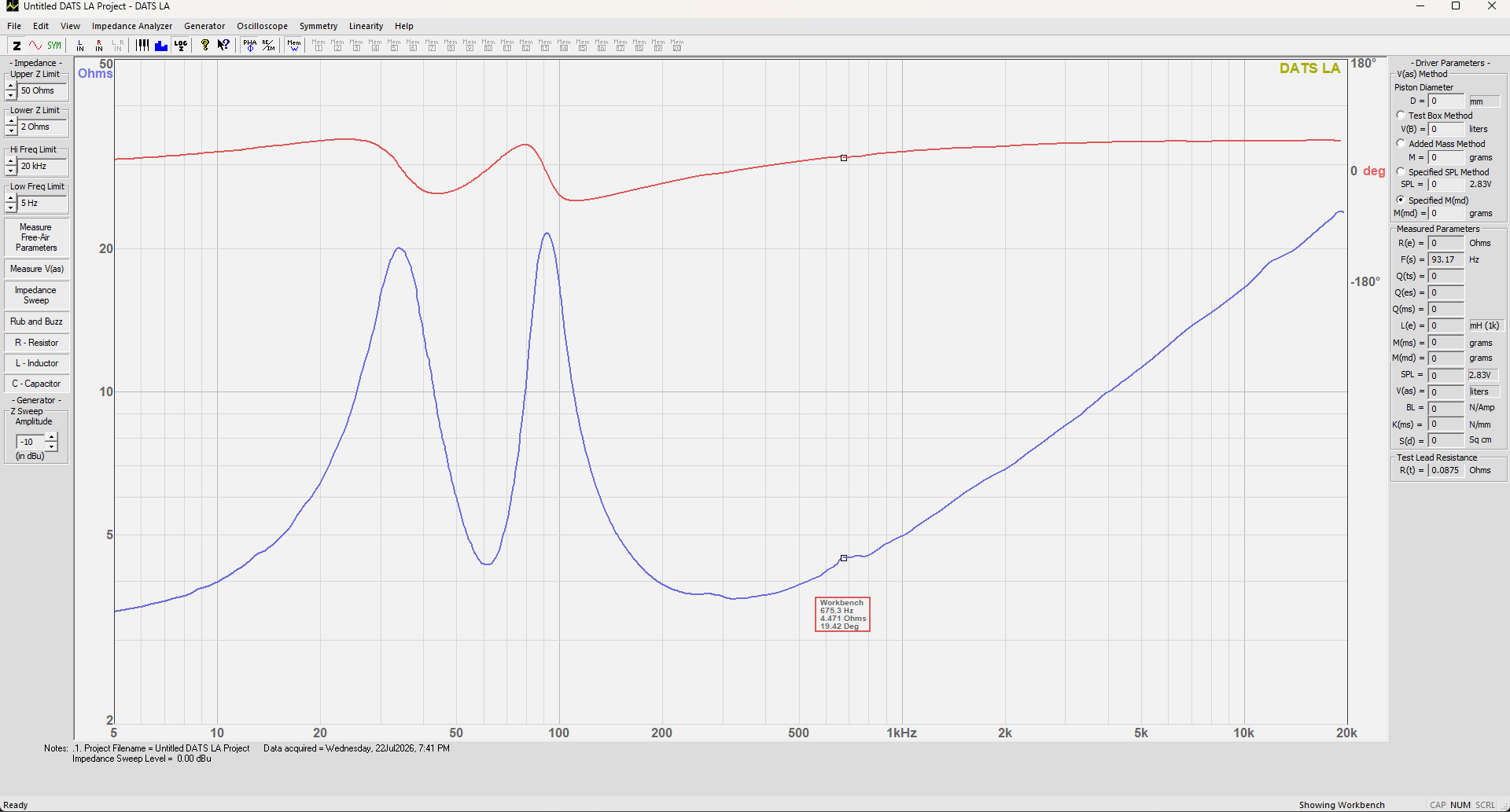
(13560/680)/2 = a half wavelength of 9.97 inches. So look for an internal cabinet dimension of about 10 inches. A half wavelength at 280Hz is about 24 inches, so that one cannot be due to a standing wave inside the cabinet. Do a near field port measurement to check.
1 Like
Internal depth is about 8.5" and height is indeed about 10".
Edit: How might one check for audible cabinet resonances? Would this show up in distortion measurements?
I wish my 3D prints looked that good.
If you want to look for leaks put a low frequency sine wave in and listen for the leak with a stethoscope at the seams.
1 Like
There is a reasonable chance it would go away if you put the lining on the walls.
3 Likes
True enough!
Honestly though, I’m surprised the box doesn’t ring more than it does. It really feels pretty solid once the rear/front were bolted on.
Well I made a mistake, the brace ‘beams’ are way too tight to slide into the T-slots. Making new ones at 98% width to see if that helps.
Great job on the build. How do they sound? This project has me curious.
1 Like
Well, it has no crossover and the tweeter is disconnected. But I’d be lying if I said I didn’t play some tunes anyway while I was playing with REW. That woofer is really quite nice for the price, and I see the 8 ohm variant is on sale at Madisound right now. Solid bass in this cabinet even without bracing and such. I’m impressed so far.
On the 280 Hz blip - I think it shows in XMechanik’s post around 310-320 Hz. Also shows in Amir’s testing too. He just called it a resonance without further thought.