I figured since the two channel catches time/phase and I’m sim’d in VCAD on the tweeter axis, if I take individual measurements of each driver on the tweeter axis, then load into VCAD, extract minimum phase, it should resemble what’s being sim’d.
No?
I’m not sure. I have not tested your method to see if it would work. All I know is that the VCAD instructions tell us to measure each driver on its own axis. Then enter X,Y,Z offsets on the driver tabs as necessary to complete the model. As measured phase is used instead of minimum phase.
It sounds like you are trying to make some weird comparison to single channel measurement system. Please forget about minimum phase, it doesn’t really help for any purpose. For comparison, change listening distance in VituixCAD preferences to measurement distance, say 1m.
Complete typical single channel 3-measurement process for delay determination. Use Auxilliary → Time Delay window to determine the delay required, uncheck “MP” boxed on that window. Enter time delay into the delay field on the drivers tab, and set driver locations to 0,0,0 in the crossover.
Personally I don’t see much point in this excersice. If you want to provide some basic validation of the design, just complete a measurement on tweeter axis at say 1m of the complete system, and then change listening distance in VituixCAD to 1m and compare the result. If you’ve done prior measurement and merge steps correctly for your design, comparison should be about as close as anyone could hope for.
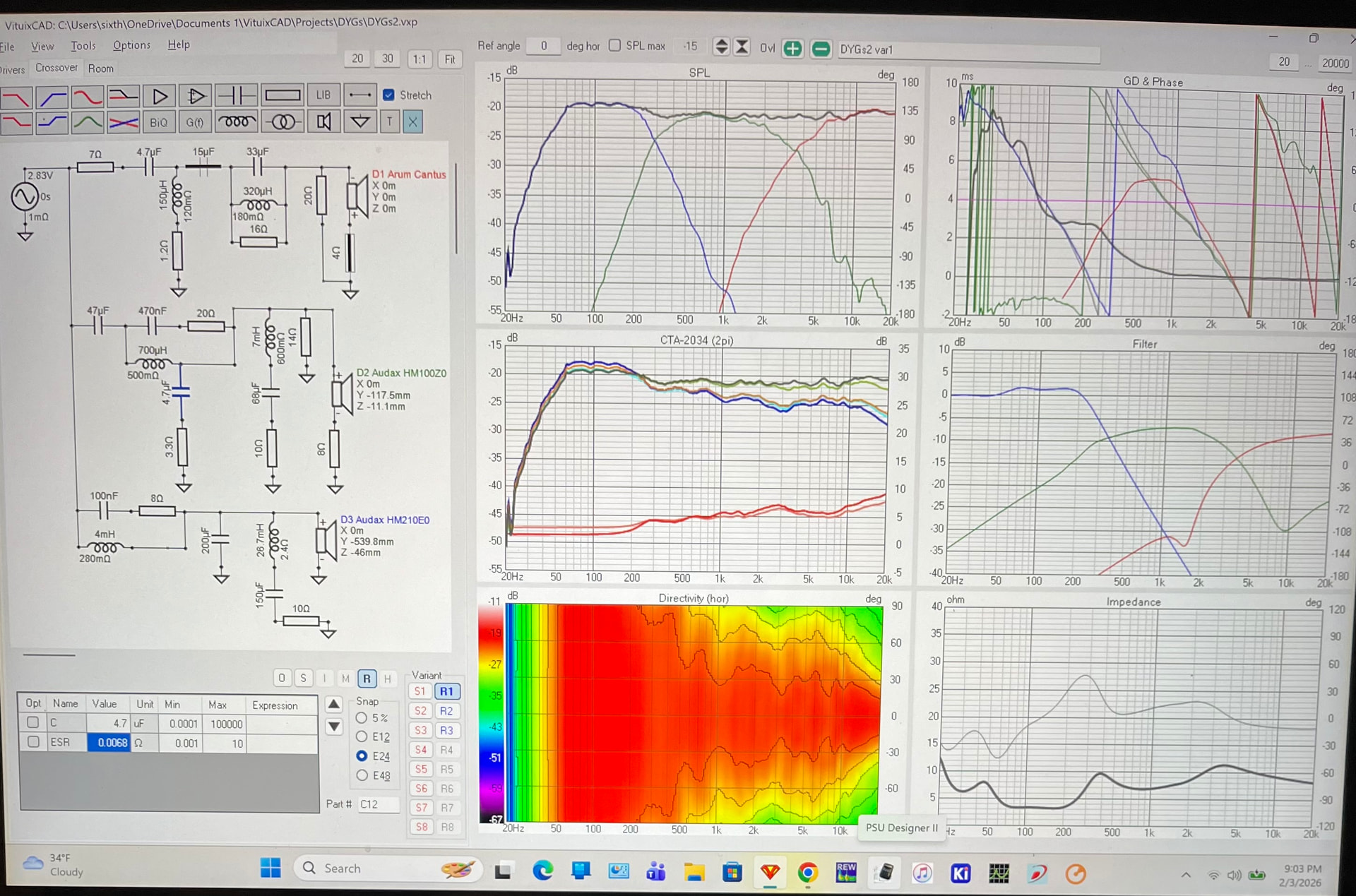
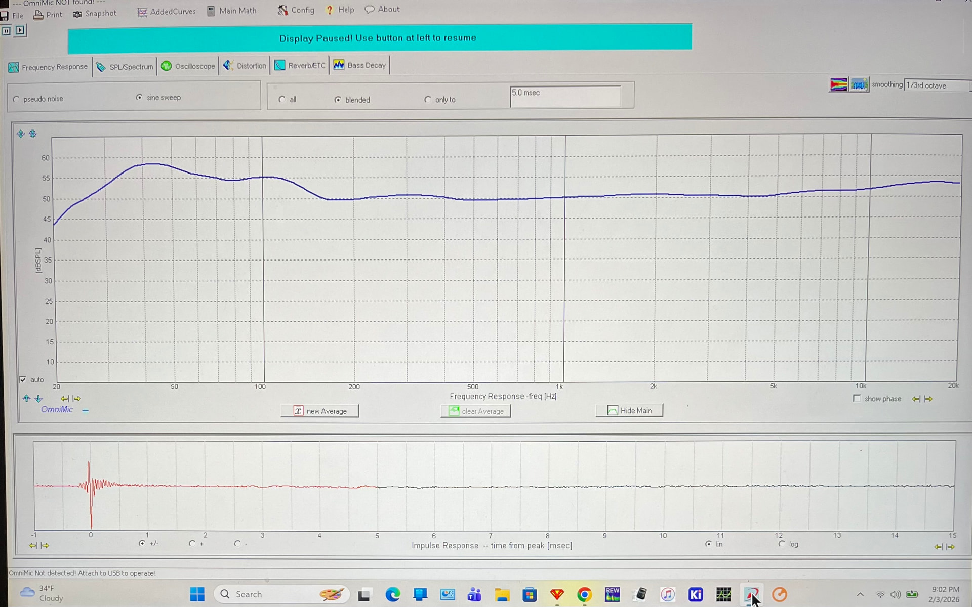
I did the standard way of measuring each driver for VCad. Entered all the offsets so I’m modeling on tweeter axis. As per my recent post, sim matches what Omnimic is measuring frequency response wise.
I’m wondering how to measure if the phase that the sim is showing is in fact what’s happening. Seems like I could 2channel measure each driver on the sim’d design axis (1M/tweeter axis) then enter those files in a new VCad model and see if everything lined up.
I’m only using Omnimic to go back and forth from listening/measuring because I have to reconfigure my interface to do 2channel measurements.
Yeah, I prefer the BBC dip or built-in “loudness” function. Just sounds better to my old rocker ears.
Unfortunately this build has me noticing I’m losing some hearing in my right ear. Makes sense as I mainly played live on the left side of the stage, drums/cymbals to my right.
I used hearing protection during practice, but never live. …then there’s the concerts..ahh such is life.
As Reet points out, if the sim is incorrect then the SPL sim won’t match actual and NEITHER will the phase.
BUT…you wouldn’t need to measure EACH DRIVER, just measure the whole speaker with two channel and you will have SPL and normal phase. Load the measurement of the completed speaker into Vcad as a driver and connect the amp to the driver with a wire.
I definitely early on had issues where my simulations didn’t match up well with my actual results, and tried to figure out why in each case - as it was always user error somewhere in the process. (This was true in PCD as well as Vcad.)
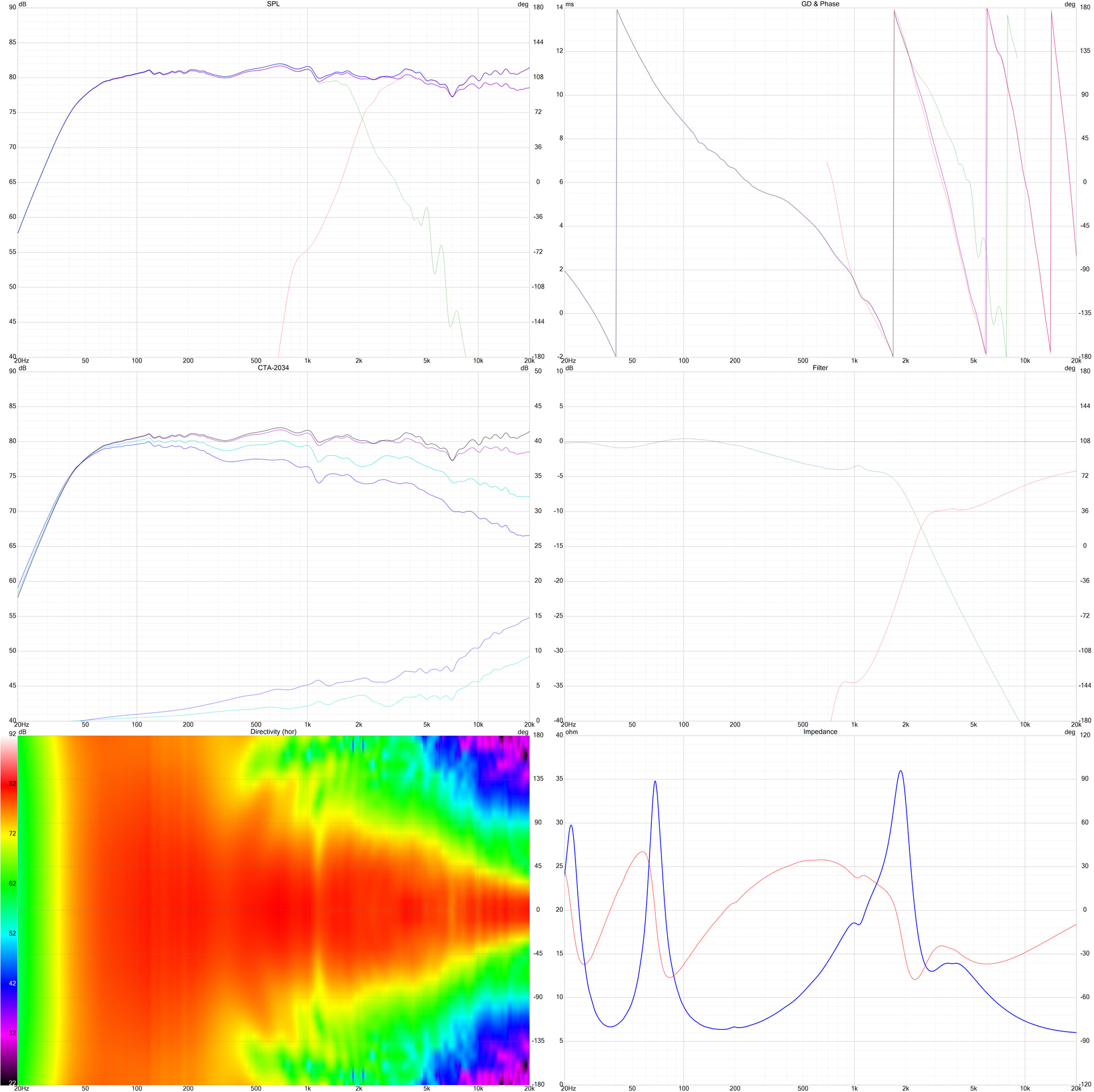
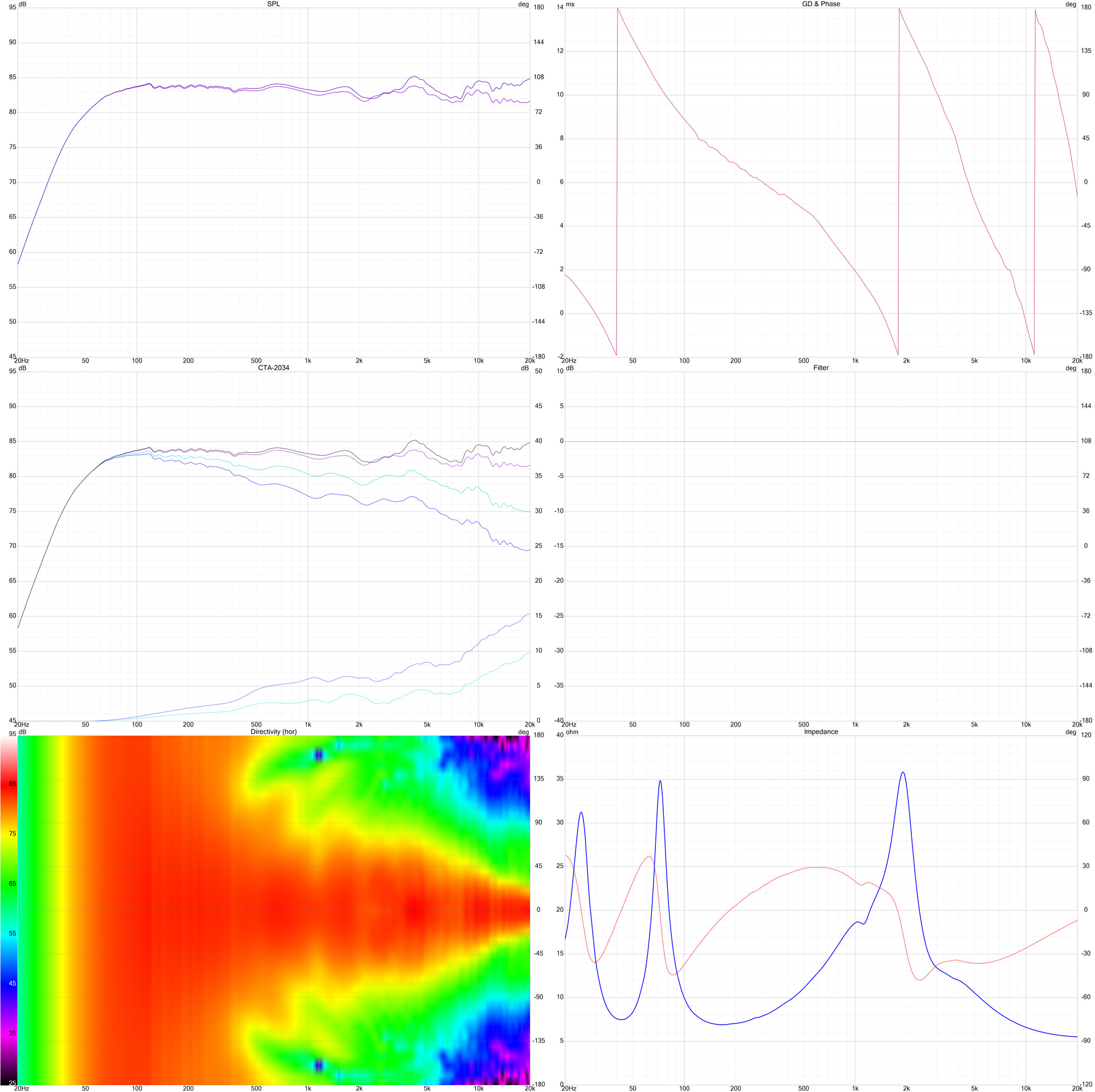
Below is a simulation in Vcad for 2 meters followed by actual measurements at 2 meters (10 degree increments horizontal and vertical) and impedance with DATS. (This was a modest sized two-way, I realize the challenge you would have with your rather large speakers.) But my point is, Vcad is very accurate if given very accurate data.
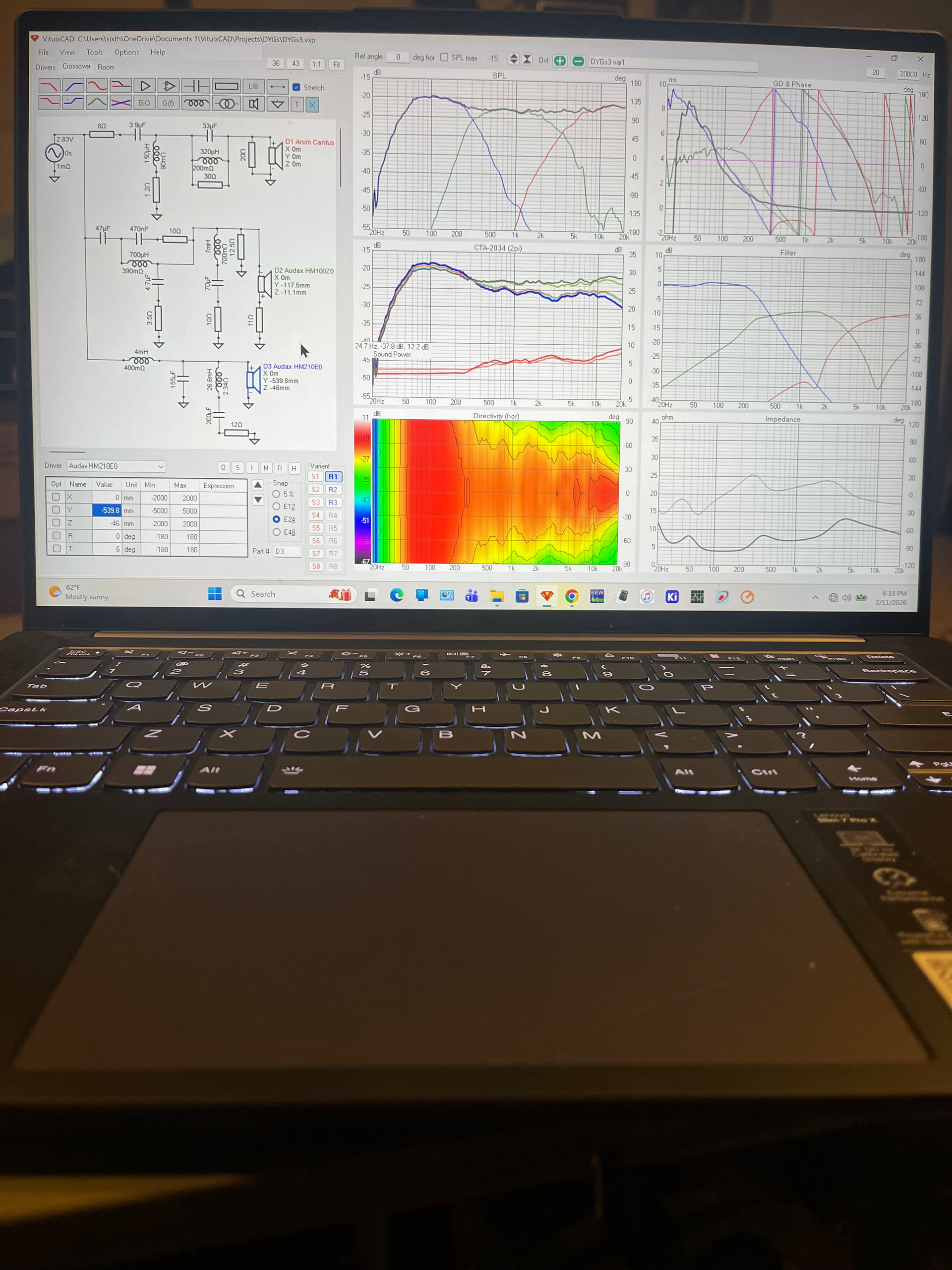
SIMULATION (you can see the individual drivers SPL, phase, and filters)
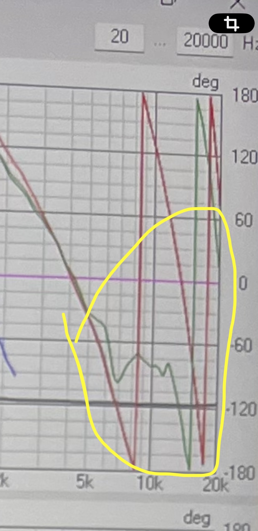
Frequency looks the same, but the phase tracking is off. Phase looks right with tweeter inverted, mid not inverted.
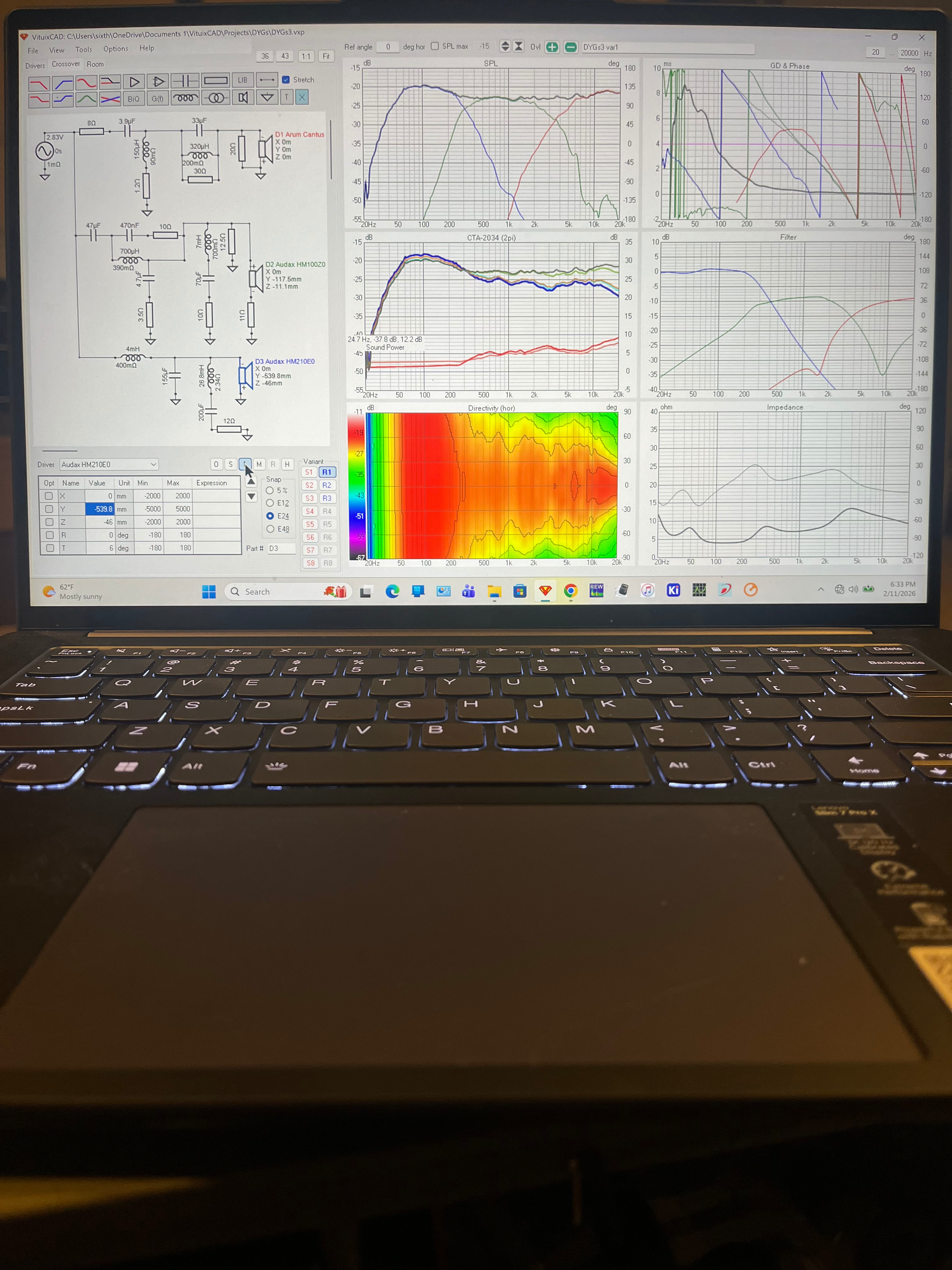
Which is better for mid/woofer?
Woofer and mid out of phase:
Wait, the log scale threw me off, woofer and mid in phase is worse? As FR is worse because the rotation lines are actually further apart, 200 and 400. As apposed to them out of phase where they are 100 and 200? Plus the FR is smoother?
I don’t know what you’re expecting. Woofer and mid are about 90 deg out of phase at the 300Hz crossover frequency. So flip one 180 degrees and it’s still 90 deg out of phase, so on-axis response is rather similar, but slope of high pass and low pass response is not the same, so phase interaction over wider frequency range is slightly different with one arrangement over the other.
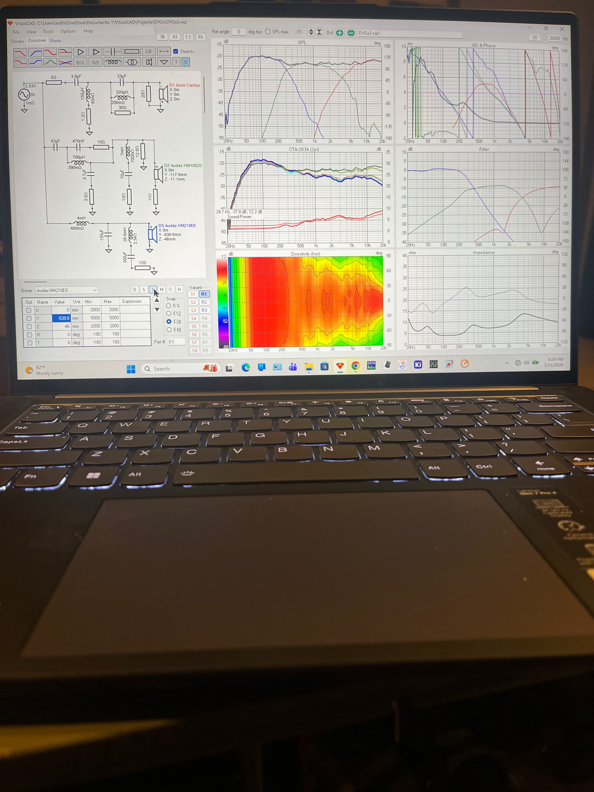
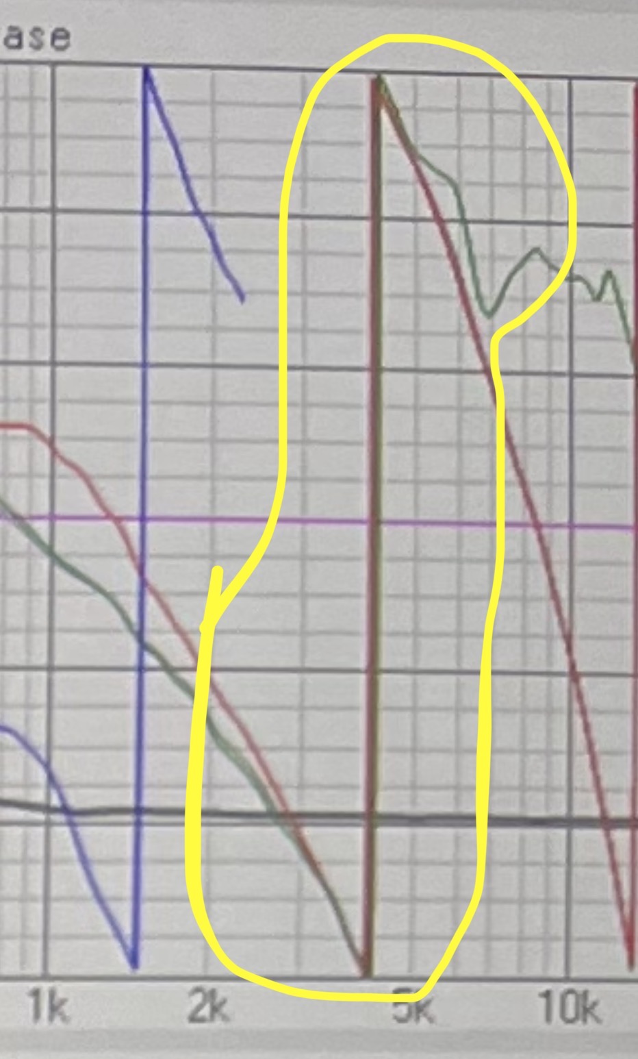
Why does where the phase wraps change from 4K to 8K just by changing from mid + / tweeter - to mid - / tweeter + ? Seems like that shouldn’t matter, both are out of phase with each other?