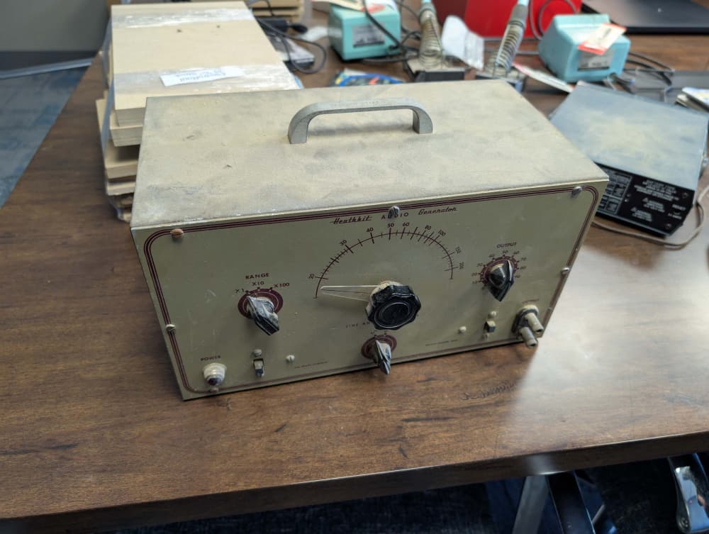
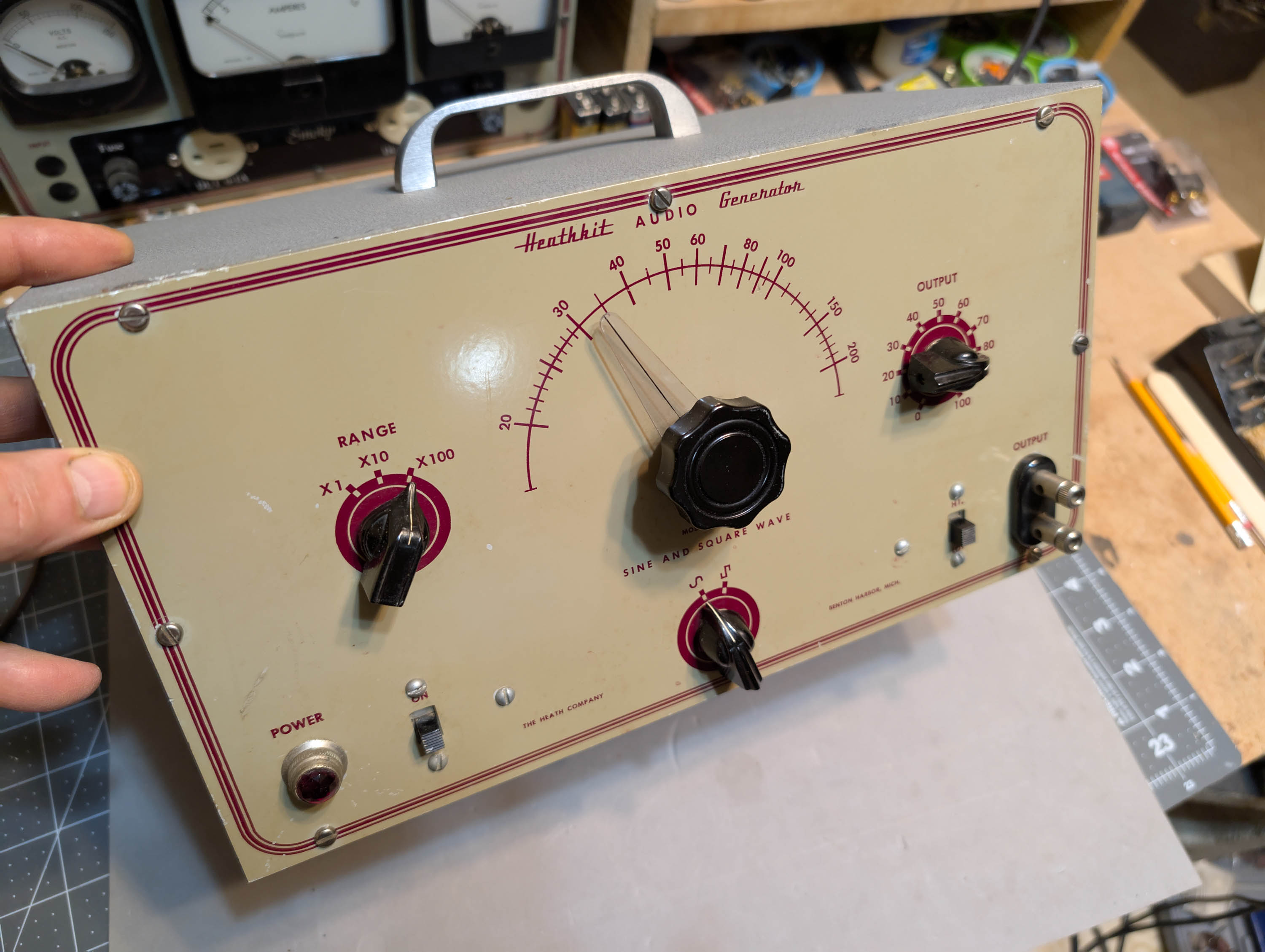
I’m restoring an old audio generator from yesteryear. It is a classic 1950’s Heathkit AG-7 that I got free from @PWRRYD and @MarkS . Thanks, guys! I know, I know, most people will say that these old units are completely obsolete and not really needed anymore. But breaking in new drivers using a vintage piece of test equipment is just plain cool!
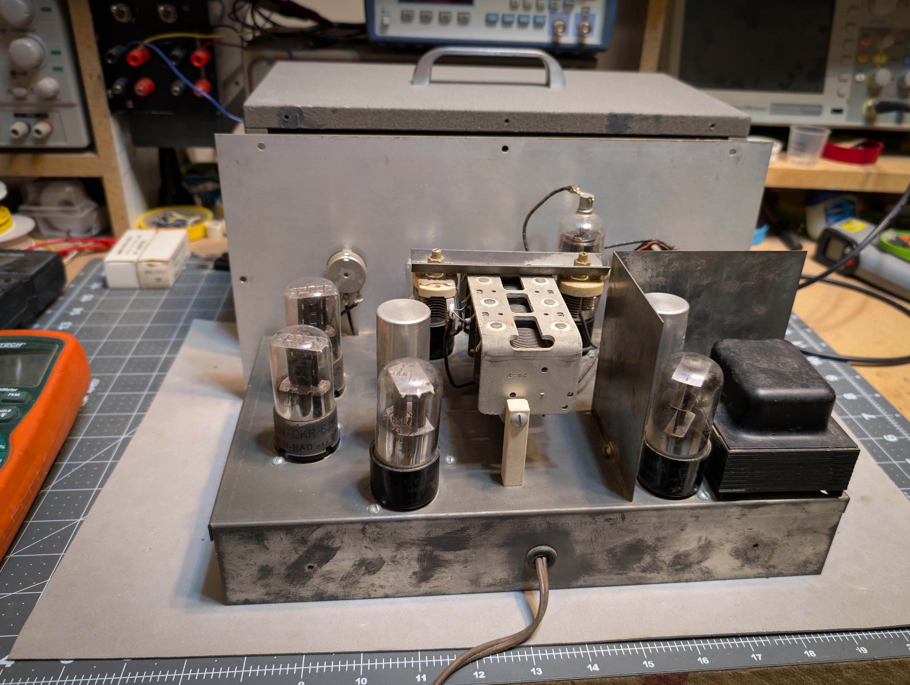
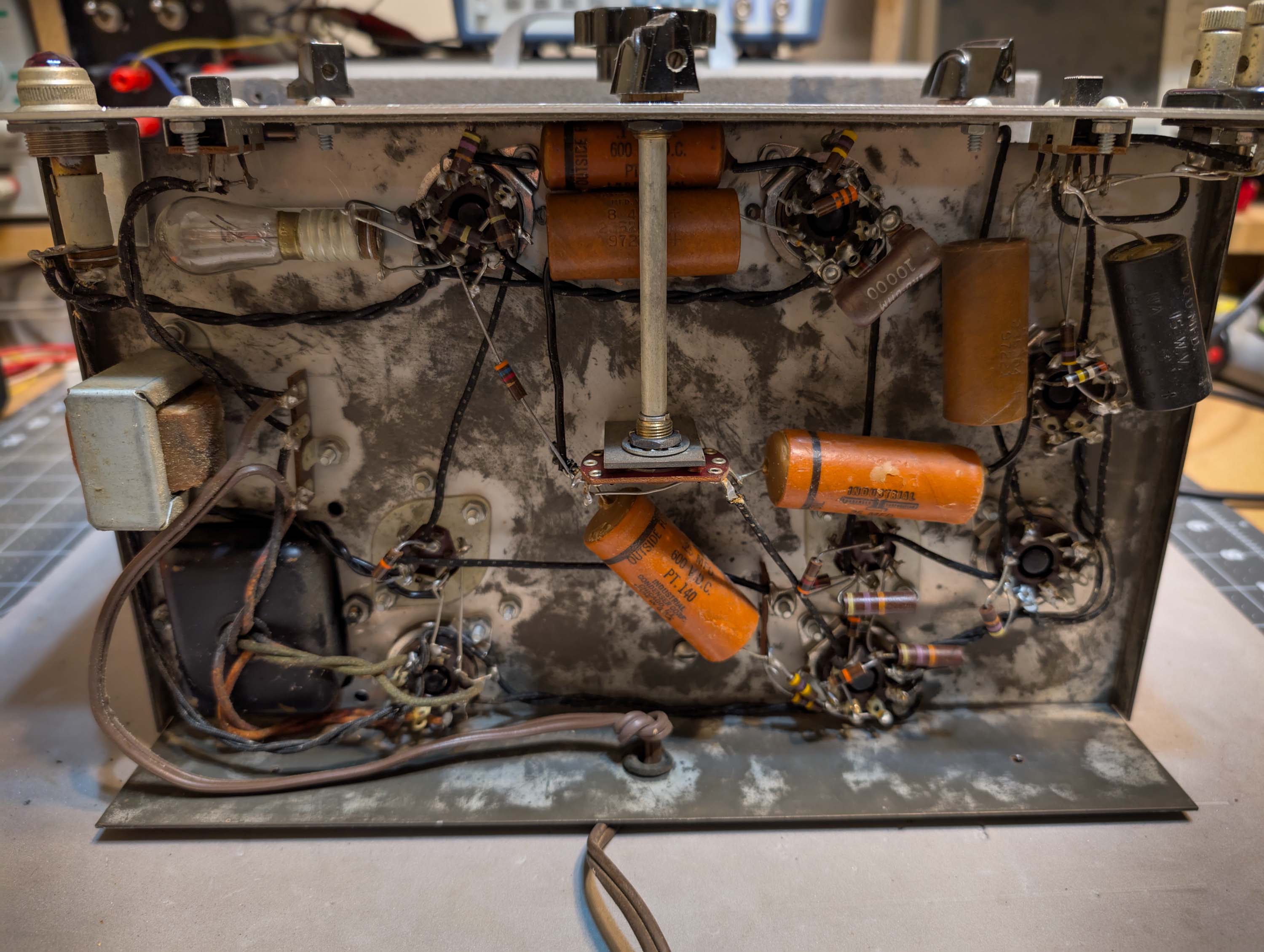
The project is about half done at this point. I cleaned and polished the cabinet and tested all the octal style vacuum tubes. All tubes check good to excellent. The transformer and power supply choke also tested good. Surprisingly, all the power supply and coupling capacitors tested good as well, but most of them are somewhat leaky after 70 years, so they will all need to be replaced. Finally, most of the carbon resistors tested good.
They are all the squared-off-end Allen Bradley style, which seem to last forever. Only a couple values were out of tolerance.
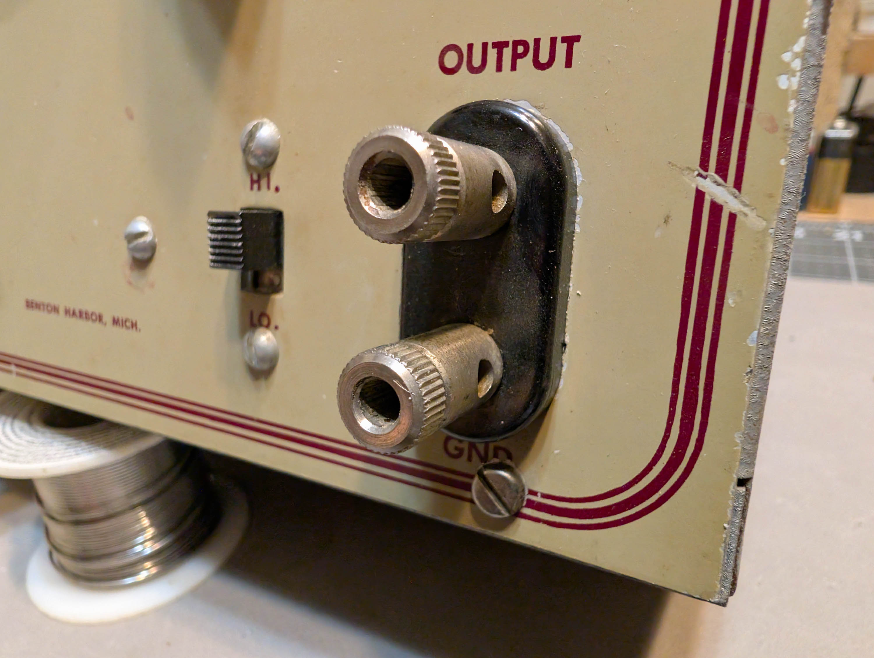
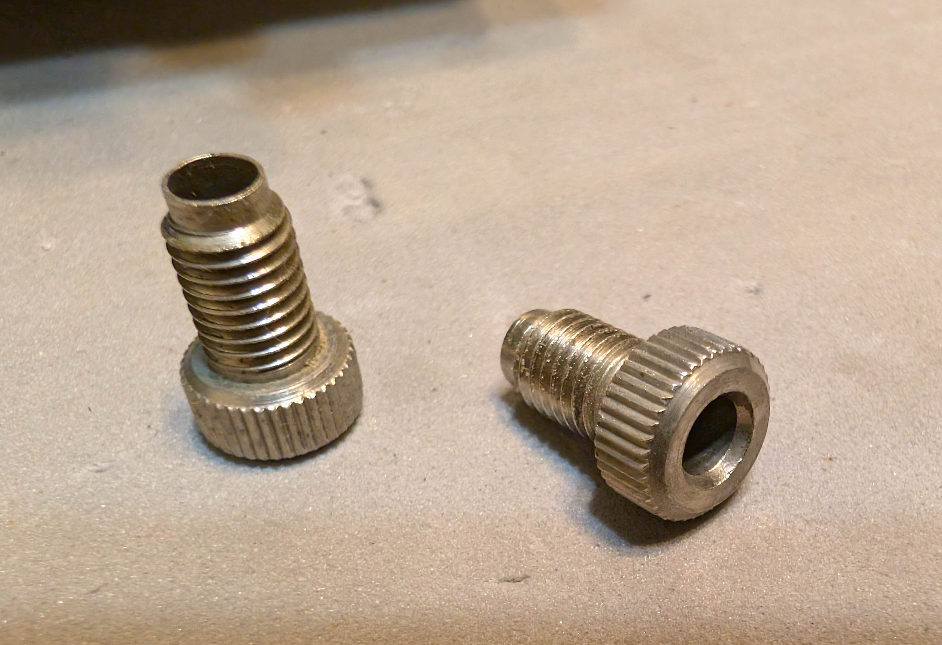
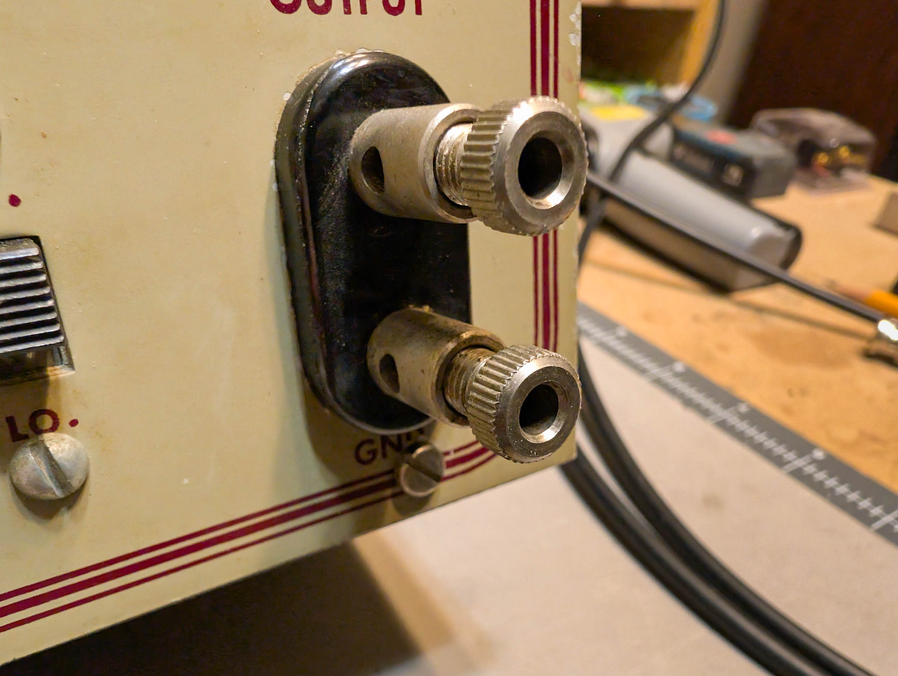
The front panel sports a solid brass dual banana jack output connector. This is the highest quality dual banana jack that I have ever seen on an old piece of test equipment.
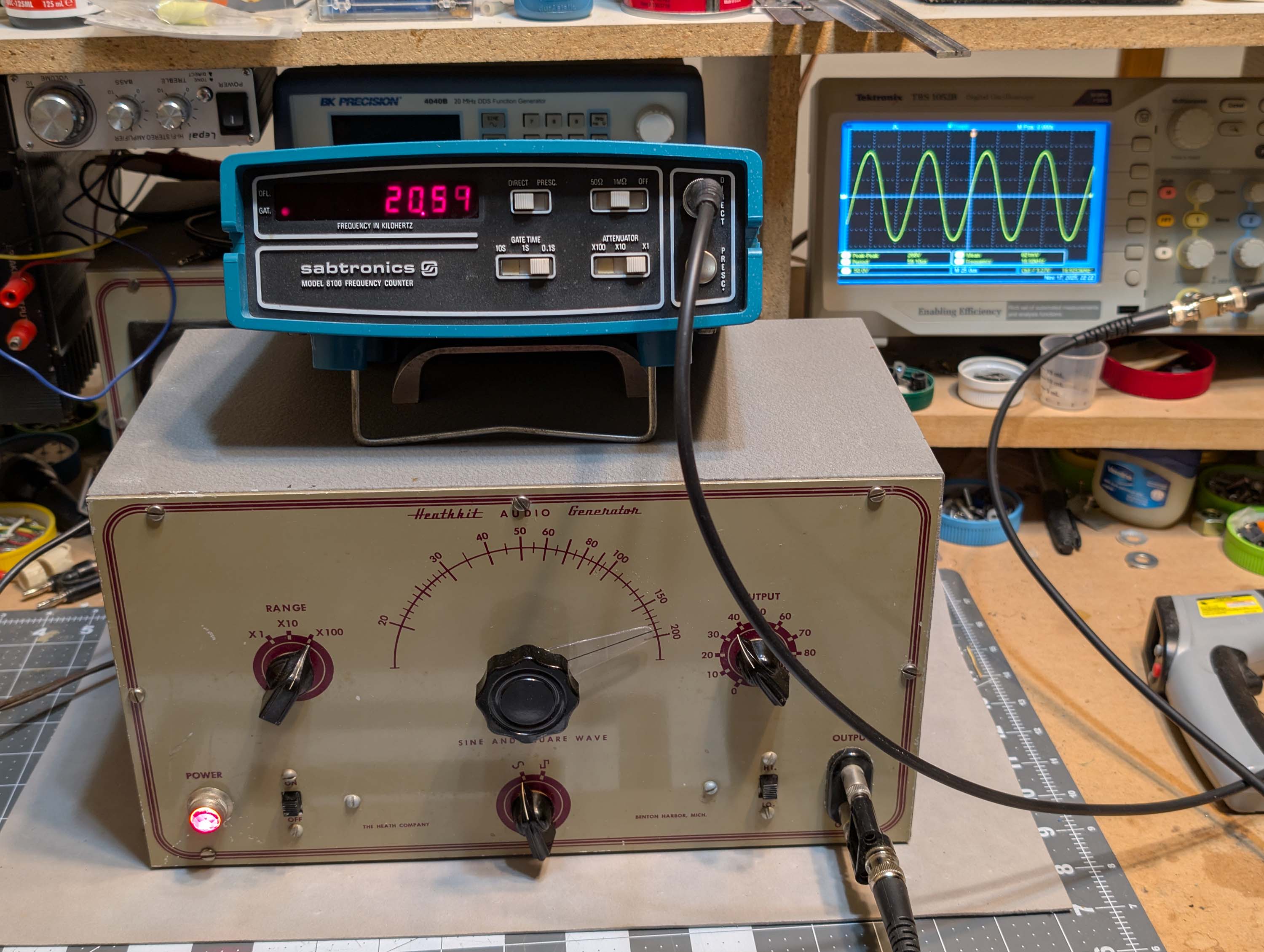
Even with all the old capacitors, the generator still works. Here is a pic of the generator outputing a 20kHz sine wave to the Sabtronics frequency counter that @ron_e gave me at IowaDIY 2025:
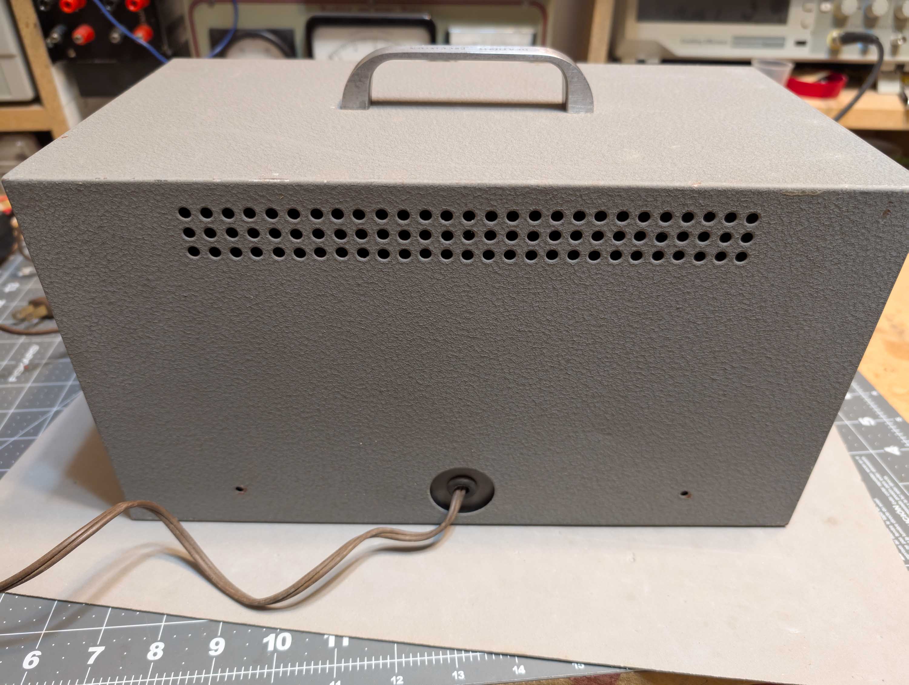
Just added a power supply and new input jack. The power input jack on the back was actually a 3.5mm (1/8" mono) TS type jack that is typically used for mono audio connections. So, I replaced it with a standard 2.5mm power inlet type so that I could use it with the 12VDC 4A power brick that @jr-mac gave me at DakotaDIY several years ago. It works great now; very accurate at 100kHz and above. At audio frequencies from about 100 to 5000Hz, the counter measures about 1 to 2kHz high at all frequencies, but I think this might just be a matter of going over the calibration instructions. I do not intend to use it at audio frequencies, so I may just leave it alone.
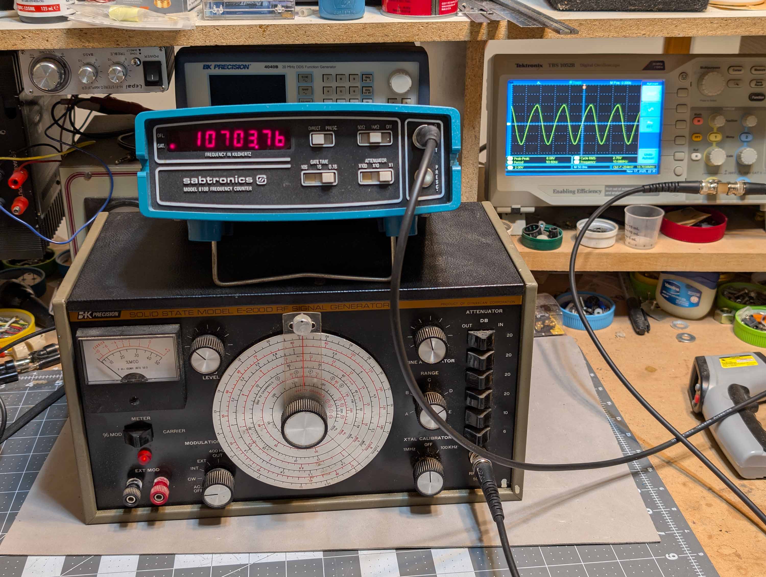
I have a B&K model E-200D RF Signal Generator that I am restoring. It is designed for aligning AM and FM broadcast band receivers and can output modulated RF signals in several ranges from 100kHz all the way up to 216MHz. This Sabtronics counter will work very well for calibrating the output for my testing work at 455kHz, 10.7MHz, 95MHz, etc. Here is a pic of the counter being used to align the curser marker dial on the E-200D to precisely 10.7MHz.
Thanks @MarkS . As I worked on the unit, I noticed that the original soldering and lead dress looked very clean and professional. Did you build this generator from a kit back in the day? Or was this a factory assembled unit?
This is a standard 3 watt, 120vac small base type incandescent light bulb (like some of the old Christmas tree bulbs of yesteryear). To paraphrase from the Heathkit manual circuit description, this bulb is being used as part of the sine wave oscillator feedback network. Both positive and negative feedback are used in a closed loop around a 2 stage amplifier circuit to create the sine wave. The frequency of this sine wave is controlled by resistors and variable capacitors in the circuit. The 3 watt lamp acts as a non linear resistor in this circuit to stabilize and control the amount of feedback applied.
Great job on the restoration! You are gathering quite a collection of vintage test equipment and have a few that are certainly worthy of displaying in your listening room.
Bill - If you’re ever in the Minneapolis area you should visit the Pavek Museum of Electronic Communication (LINK) in St. Louis Park. I visited a long time ago and they have a treasure trove of historical gear.
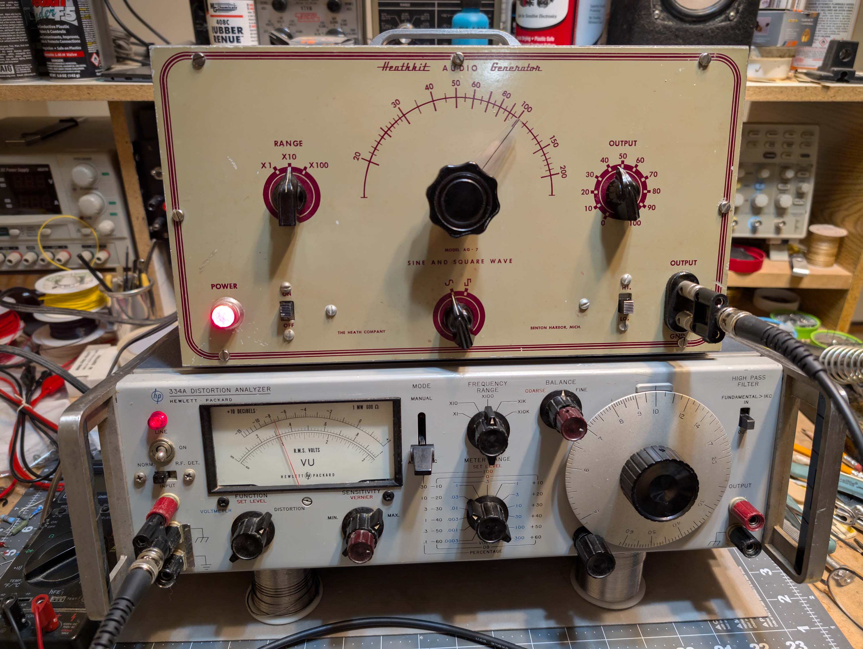
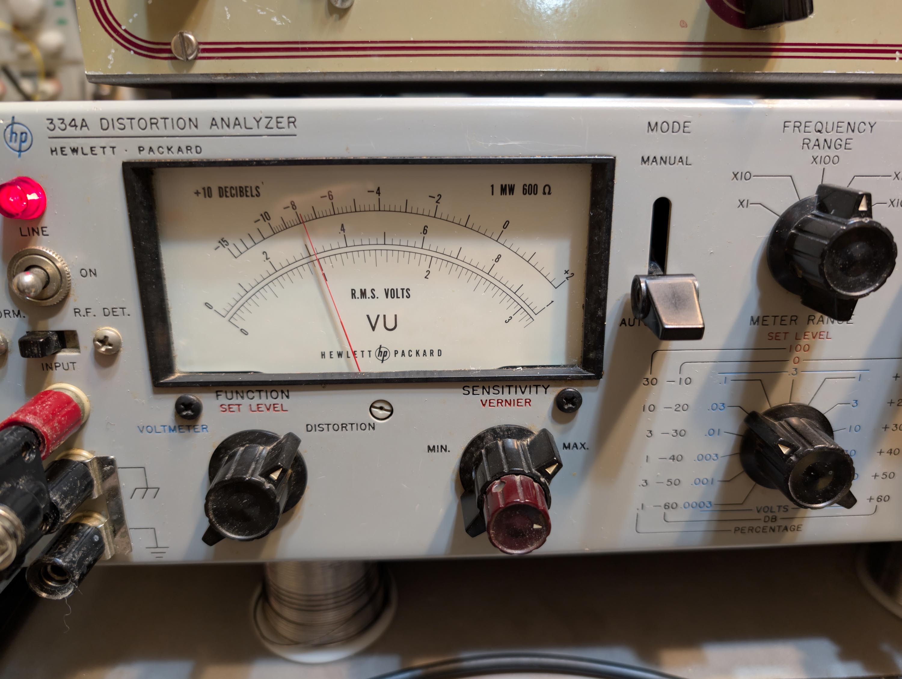
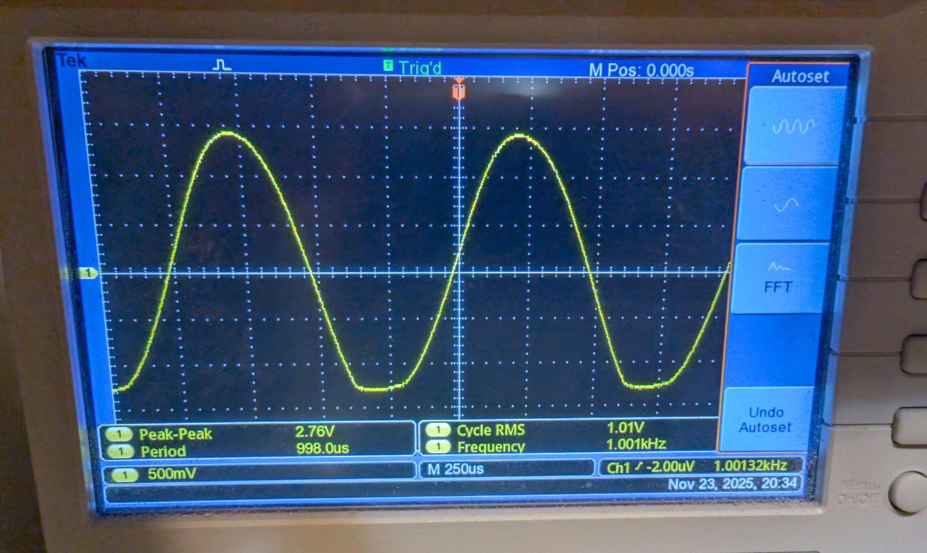
Today I fired up @ron_e 's old HP334a distortion analyzer and tested a 1kHz 1V RMS sine wave coming from the old Heathkit generator. The generator still has all the old, original “waxy” paper caps, electrolytic caps and carbon resistors in place. As you can see in the photos, harmonic distortion measured 3.2% Per the Heathkit manual, distortion should be about 1% or lower. So, the old, leaky caps are probably doing a number on the stablity of the oscillator circuit. When I get my Mouser order in next week, I’ll install the new parts (12 caps and 4 resistors) and re-run the distortion test. I should be able to get this down to 1% or less.
Note that previously I showed a scope photo of a 20kHz sine wave from the generator. It looked fairly clean and probably had lower distortion. But I didn’t have the HP334a set up for testing when I took that photo. When I tried to measure the distortion at 20kHz today, the oscillator mysteriously quit working at the highest range setting. So I could only measure at 1kHz.
Finally got the old Heathkit working like new again. Replaced all the electrolytics, paper caps, and a hand full of out-of-tolerance resistors.
Also flushed and lubed all switches, including the solitary output pot and tuning condenser, using CNC no residue contact cleaner. Then I followed up with a light lube of the metal to metal contact switches with deoxIT D5 and a light lube of the carbon pot with deoxIT F5 fader lube.
After all that cleaning & replacing, I powered it up again, but the sine wave output was still heavily distorted. THD measured 3 to 7% or more, depending on load and frequency. After much head scratching and going down several dead ends, I discovered that I had inadvertently soldered one of the new 10uF 500V coupling caps to the wrong tube socket lug. The cap needed to be connected to the plate lug of the 6K6 tube but I had connected it to the screen grid lug by mistake. The oscillator was therefore starved for current and clipped the sine wave badly.
After correcting this one simple mistake, the distortion problem disappeared completely. The generator now meets factory specs with less than 1% THD from 20-20kHz when driving a 1Vrms sine wave into a 10k load. Here are a few pics of my journey showing my setup, the mfg’s spec sheet, and some of my measurements:
All in, cost was about 25 bucks for new caps and resistors. Not including my labor. I also spent $25 for two NOS tubes (6K6 and 6J7 tubes) because, even though they tested good on my tester, I thought, incorrectly, that they might be the source of the distortion problem. Lesson learned. Moral of story: Always double check your own work before looking elsewhere for the problem. Thanks again to @PWRRYD and @MarkS for giving me the opportunity to restore yet another Heathkit classic. And thanks to @ron_e for the distortion analyer. This analyzer is working very well and can make accurate measurements down to as low as 0.03% or so.