I’ll update these here as I progress…
1 Like
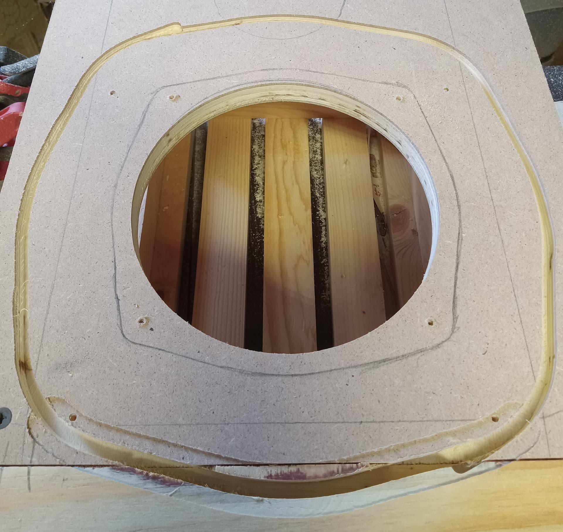
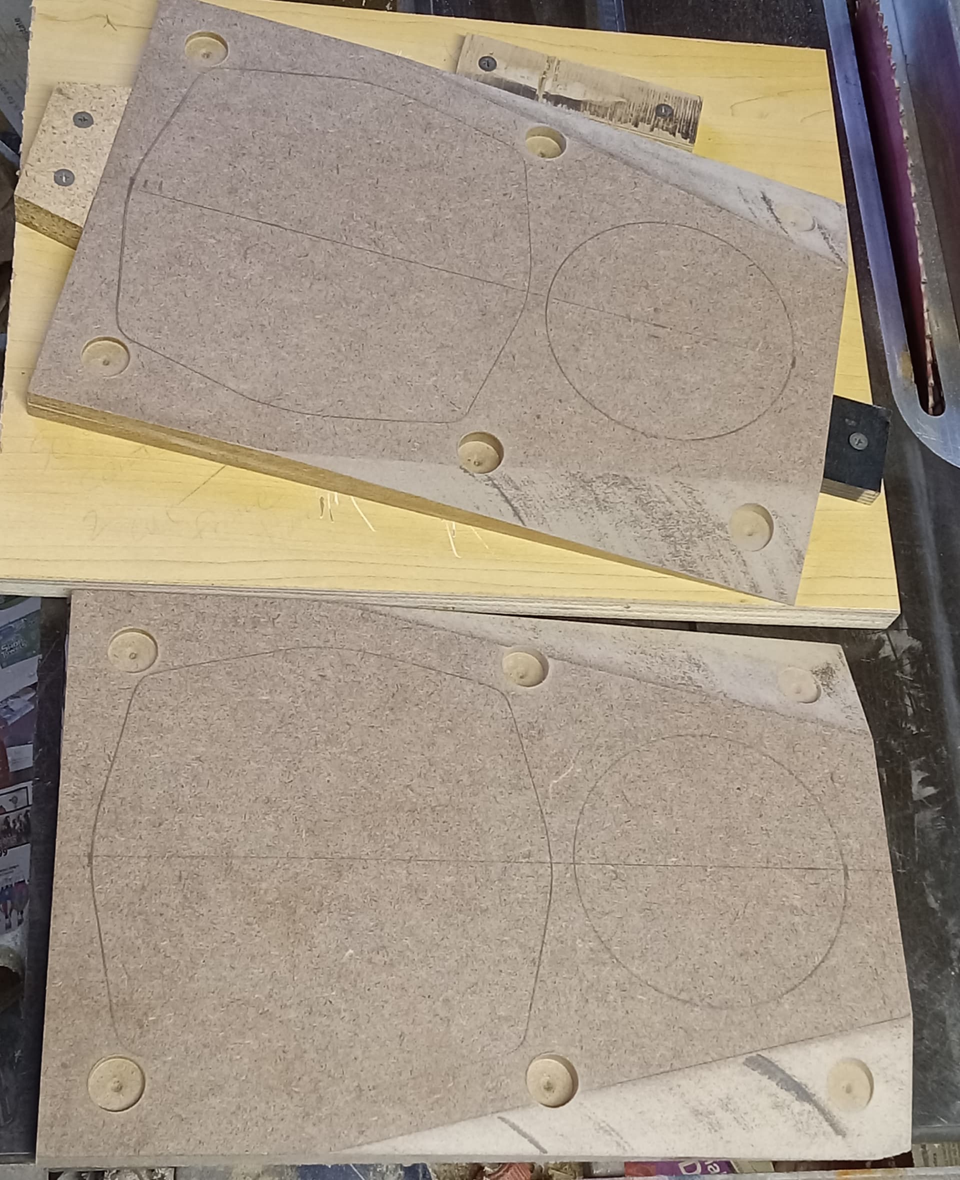
First template was not ideal, so I’ll have another go at the recess. The driver appears to not fit the same in all 4 orientations. I also left no wiggle room the first time, so the second will be shimmed a bit larger.
It’s a shame that any driver company uses pincushion frames anymore, but they do for some reason. I won’t even try to rout one out. Looking forward to the results!
Cheers / Robert
For pro audio drivers, it is about maximizing space on arrays.
1 Like
I started the second attempt for a better routered pin-cushion shaped rebate today. I used the previous through hole template because I knew it was good and worked well. Once that was done, I bored mounting holes because they would be needed.
I then bagged the driver with a standard Walmart plastic sack, and wrapped the frame and bag around the mounting perimeter with about 2 layers of blue masking tape. The open end of the sack was toward the surface underneath that I was using for this process, and then I twisted and stuffed the closed tail into the pole vent and placed a strip of tape over it. This is meant to keep the sawdust out of the driver, and allow using the mounted driver itself as the initial shape. The two layers of tape is for easy mounting clearance and to keep the router from cutting open the bag while routing.
I used the 3.5” round router base on my Ridgid palm router with a 1/4” straight bit. I carefully did about 4-5 passes around the driver, cutting deeper every round. Take this slow, because any imperfections will show in the next step of routing inside this outer perimeter to cut the actual rebate and become my future template.
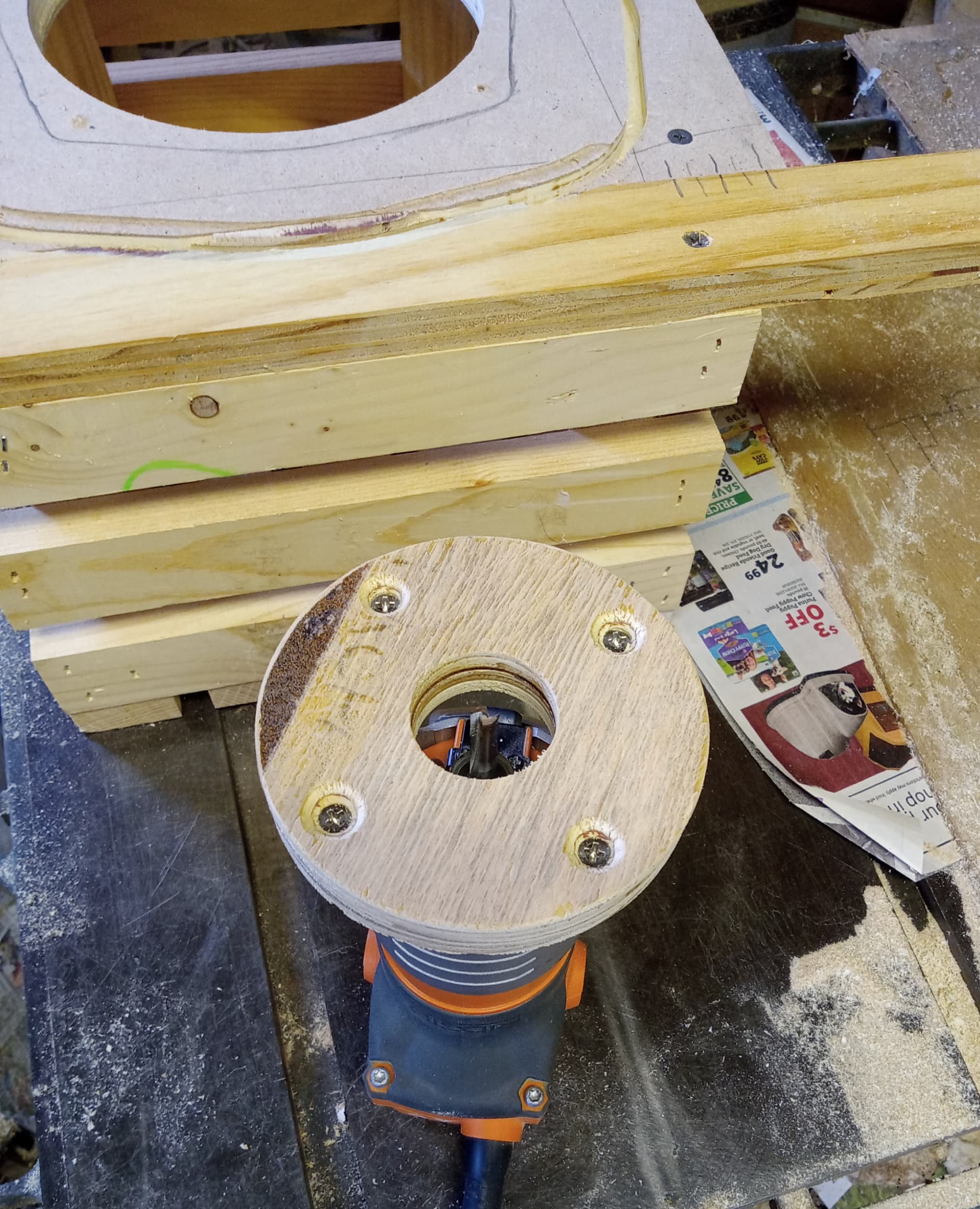
Most of the time, this next step of routing inside the just made outer perimeter is done with a bushing to space the inner cut to the actual driver dimensions. Since I used a 1/4” bit, and a 3.5” diameter base, I had to space inward another 1/4”. This means use a base of 4” diameter for the perfect cut. I have a 4.125” hole saw, and this cutout wheel hub sits at about 3 29/32”. I will use this as a secondary router base to cut almost true to the frame itself. I will likely wrap a few layers of tape around the hub to start and not make it too large initially.
The hiccup here, was I did not have the proper thread screws at the proper length to mount it to the router. I will get some tomorrow to mount and attempt the next step. I need to first cut out the center of the outer rim so that this is possible.
More to come later. Sorry I did not take any photos, but felt this was pretty self explanatory.
1 Like
Make sense to me. Still a bit tricky though. nicely done.
I am holding off cutting out the center as I considered today a win. Why risk a bad end to great progress?
When I did the B&C 5.25” coax pincushion cutouts a few years ago, I used square jigs with aligned corner pins. This allowed me 4 tries to get the curves and corners right. Then, I just rotated the jig to the next position to use the best curve for all 4 sides. It worked for me that time.
1 Like
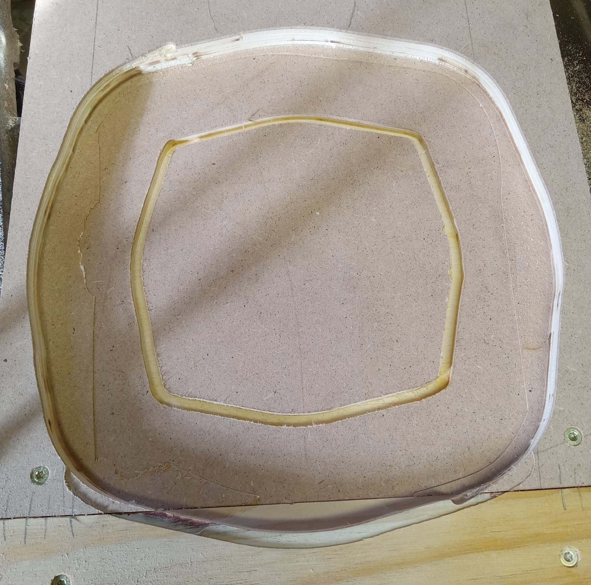
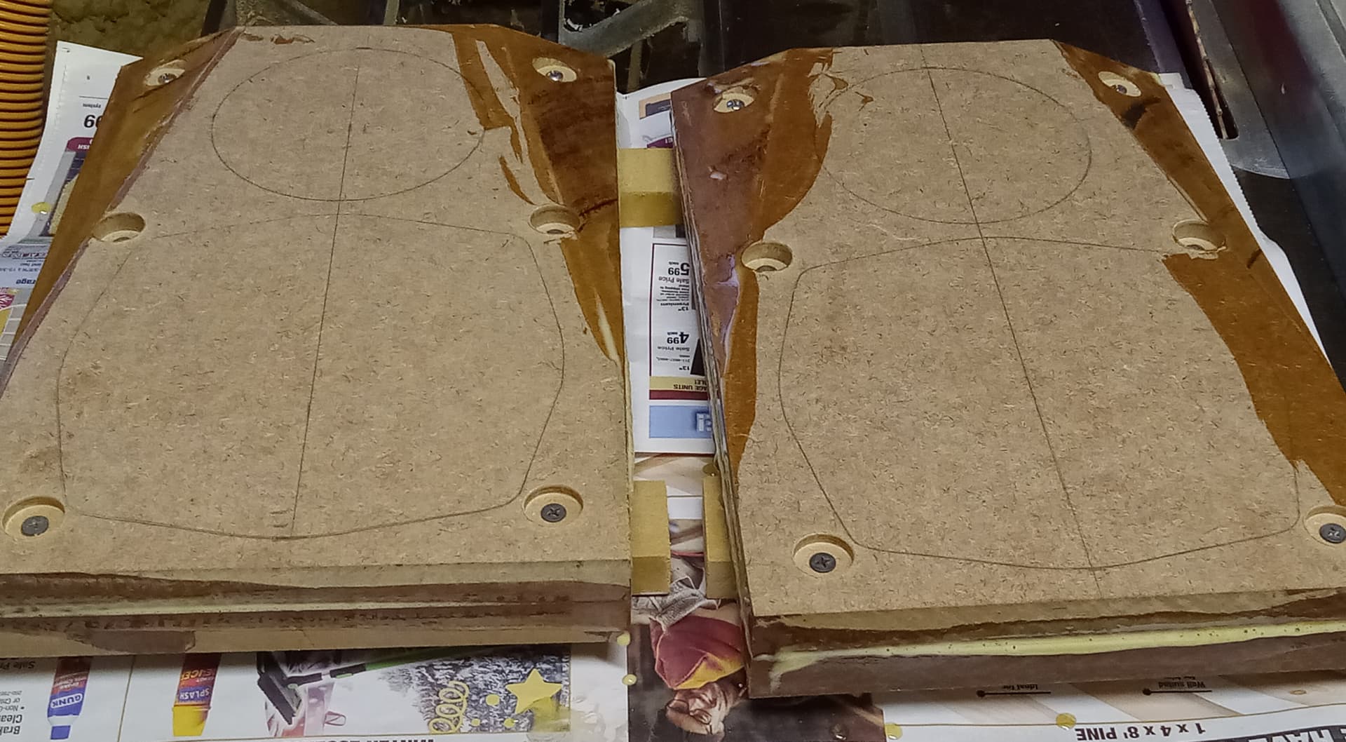
Okay, today I removed the interior of the grooved template. I made sure to leave as much inner circle attached to the template as possible. It was a good thing I did. The grooved part was about 2-3mm proud- all the way around. I had allowed for just too much play.
What did I do to fix it? I used a reversed rabbet bit!
Most rabbet bits have bearings that are smaller or same diameter to effectively remove more material. In this case, I needed a larger bearing than cutting diameter. A while ago, I bought a stack of about 10x 1/2” ID bearings for use on top of half inch shank bits. I used the last set screw collar I had to secure a bearing in place atop of a 1” diameter straight bit. The bearings measure 1 1/8” diameter, so I could reduce the cutout by 1/16” all the way around.
After this reduction, all I had to do was lightly sand the inside of the template, and adjust the corners by sanding just a bit more.
It fits really well!
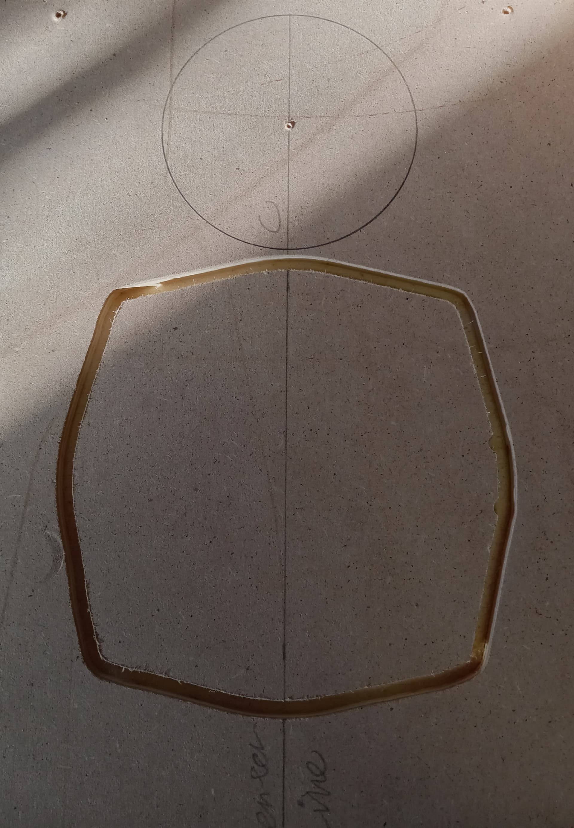
Then I tried the 110mm hole saw, and the tweeter fits well in that hole.
Next up- baffle prep….
1 Like
Good to hear. The hoops they make diy’ers go through heh. Especially when as most things it’s learning from experience not having luxury of precise/granular cnc or manufacturing processes where CAD it up, run few proto’s to refine etc. Though it is fun in the challenge of finding a way to git-r-done.
1 Like
I actually did inquire about a CNC cutout template, but was told the graphic from Beyma was not clear enough to get it done. I tried 2 methods, and the second one worked.
I’m at a stopping point for today as glue has to set up before I do any more work on them. I was toying with veneering the baffles, and while I still could, i don’t think I want to veneer the adjacent facets too. Yep, I did tapered facets on these. I’ve never done that on a build and figured “why not?”, the drivers were so difficult it set the stage for more fancy aesthetics. I did pre-drill the bolt placement so I knew where the drivers and tapers would go.
The board I used for the taper jig running vertical through the table saw was initially set up for one edge of the baffle. I set up for 2” wide at the baffle top, and then drew a line 2” from the edge on the jig to align and place the baffle. I then installed 3 stops into the board to keep alignment. C-clamps held the board against the jig while making the cut. When done, I flipped the taper jig over, flipped the stops, screwed them down opposite as before, aligned baffle for cut, applied C-clamps, and ran the other 2 edges. It was a little nerve-racking, but I managed. The angle for the cut was 21° from vertical.
Do you use measurements for your replace-able baffle new holes in the versabox? Or have a template?
About to try my 6 hole for 12.5x9, made ACM pate with 7/64 holes (or whatever bit for making 8-32 tapable holes)
I did use measurements on this one. Top and bottom bolt holes are set at 1” from edges, and the middle pair are 1” from sides. IIRC, the middle are 5.75” from the top edge. All measurements are on center, and bored with a 5/16” hole, and use 1/4-20 bolts. I have the first pair of baffles on standby and have used those more than once as a template.
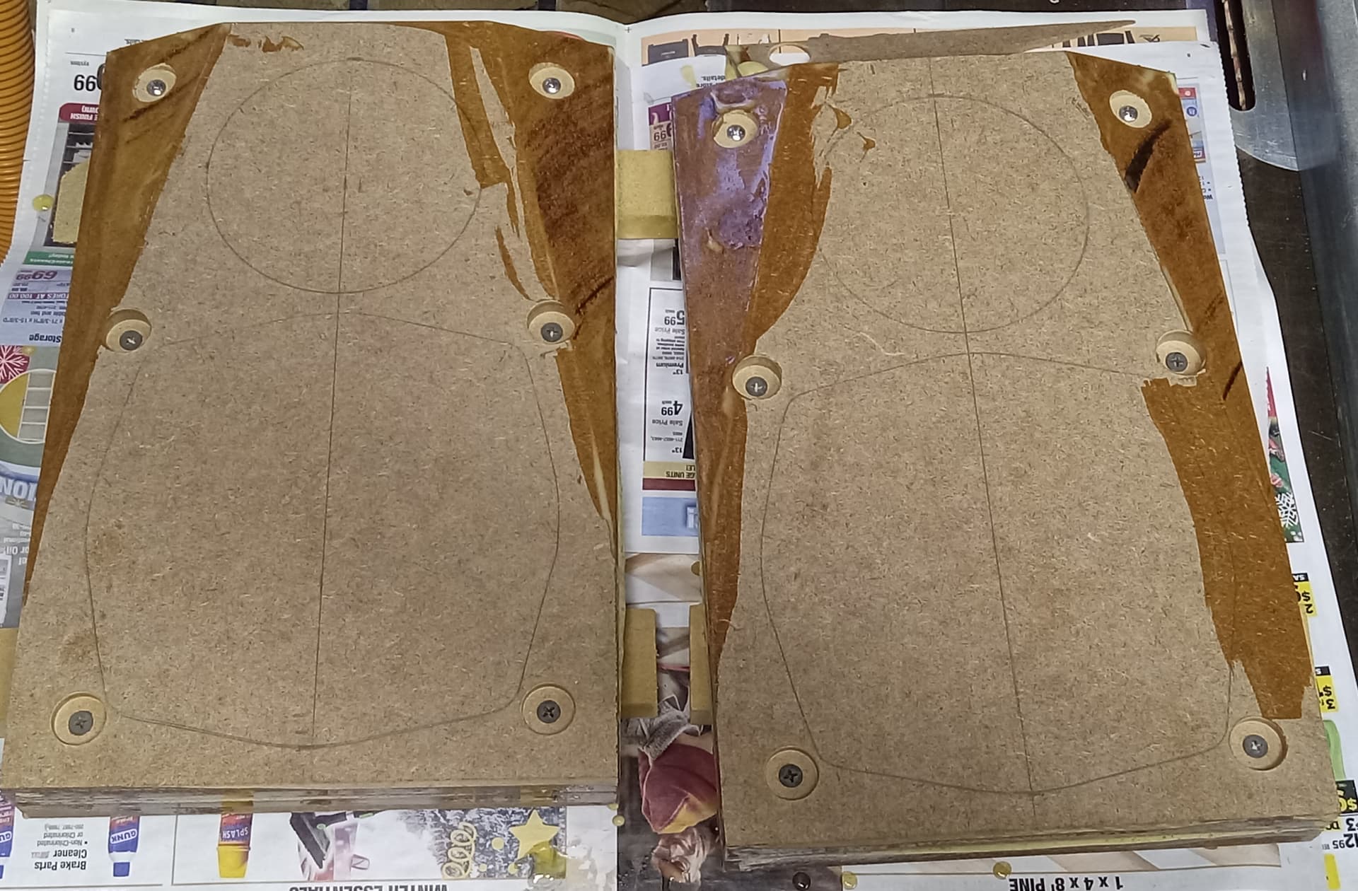
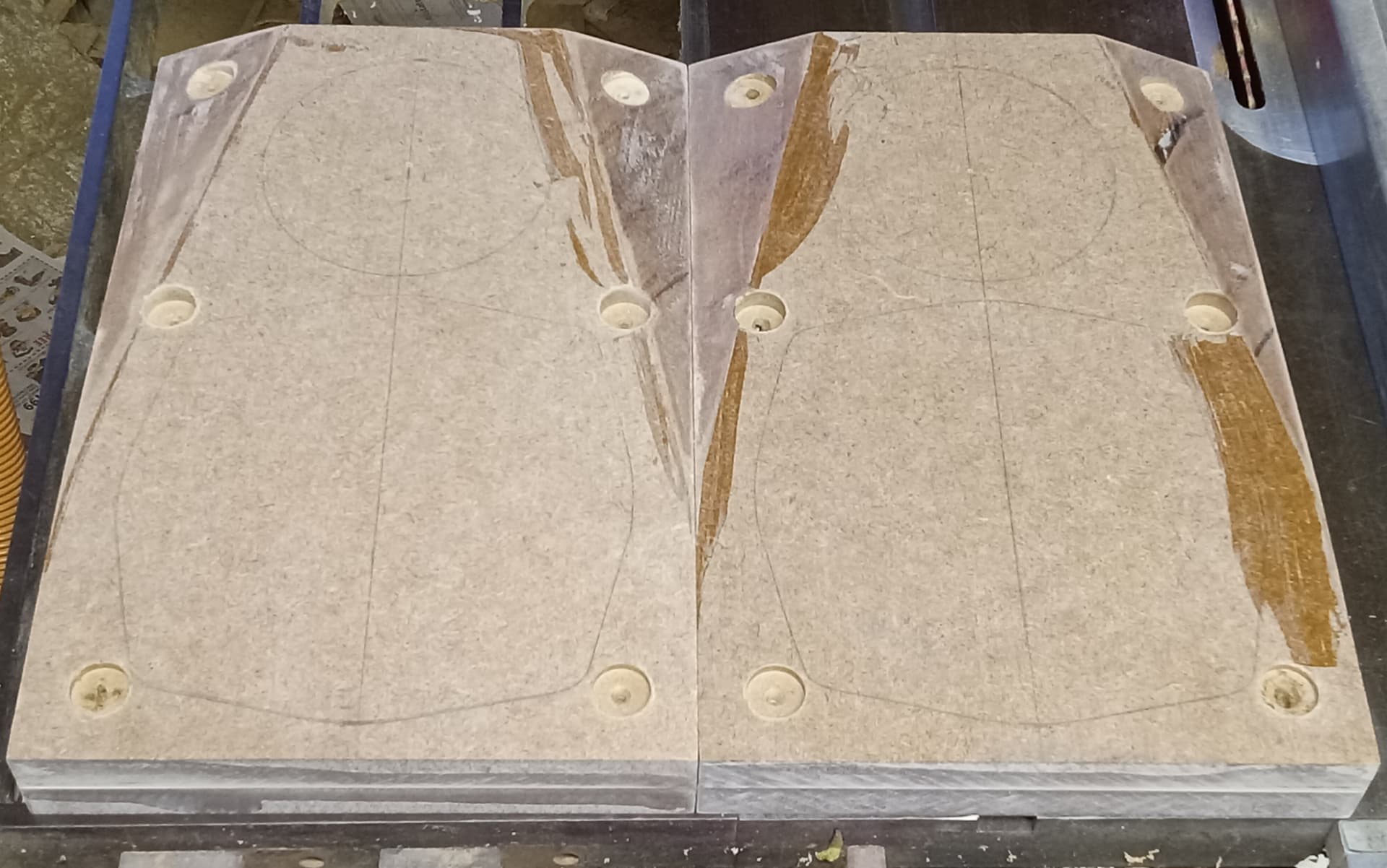
Scraped snd sanded all but the faces so I didn’t remove the pencil drawings. 4 of the 12 screws broke when being removed, so I counter bored the remaining screws adjacently to get them out. This of course chewed up the screw holes and it broke a drill bit in the process. I will have to fill with epoxy and re-bore when the time comes. This heavy dark-brown MDF is strong stuff and machines cleanly, but I’ve never had to work this hard to remove screws from MDF.
1 Like
With new drill bits in hand, I returned to these baffles this afternoon. I bought Milwaukee M35 Cobalt bits in 7/64 and 1/8 sizes because they are stronger and can take the abuse, as well as being the bit sizes I use most.
Q: Anybody ever use 3-flute drill bits? Just curious. Amazon had a set I ordered to try out…
I refaced the mounts for the furniture bolts and drilled new pilot holes through.
I cut the through holes for the woofers and scalloped the rear of the baffles because of the thickness. I am glad I had new blades for the jigsaw, or the holes would have been harder to cut through. Tomorrow, I hope to do the rebates and maybe cut for tweeters.
My stash of 12” square wood-backed veneer samples will be enough to fit vertically as long as I chamfer the top edge about 3/4”, and slightly chamfer the bottom edge. Have not decided if the facets will get veneer or paint, but I want to veneer them.
Oh, one more thing-
I am likely going to use threaded inserts for the drivers in this build to avoid breaking more screws.
3 flute bits might not be a good choice for wood products. Flute clearance is limited. Drilling debris will build up and might make for more drilling effort and heat generation. Depends on specific application. If using a drill press might make a good reamer for more accurately sizing holes. Talking thousandths of an inch really.
3 flutes can help drilling some materials where chatter can be an issue.
1 Like
Thanks, Tom, for your insight. The video for the 3-flute drill bits is more focused on metal drilling, which may very well be the intent. I was thinking they would remove more material faster as more cuts are being made simultaneously. However, buildup or clogging may indeed be a problem.
Whar does Pin Cushion refer to?