What is “terminal tripath”? Can’t seem to find it in the thread above.
I put dividers in the line to make three parallel lines with different taper ratios. I tried two lines today but the benefit was slightly reduced and dual taper doesn’t sound as cool.
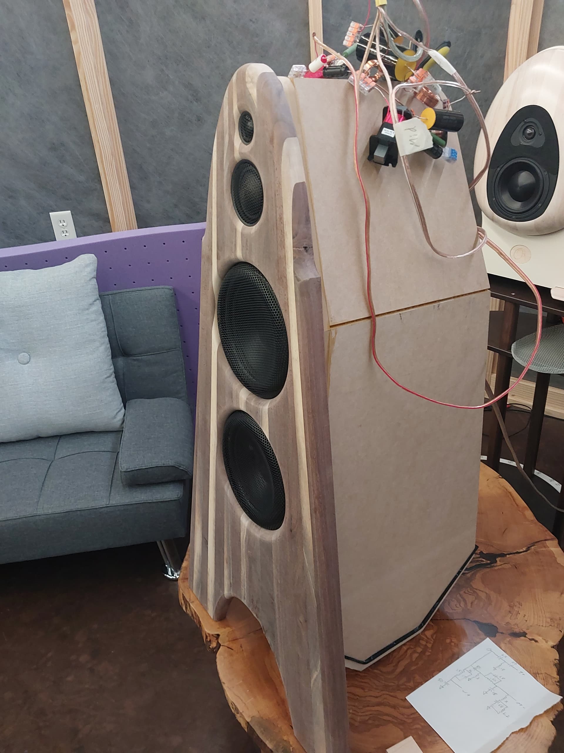
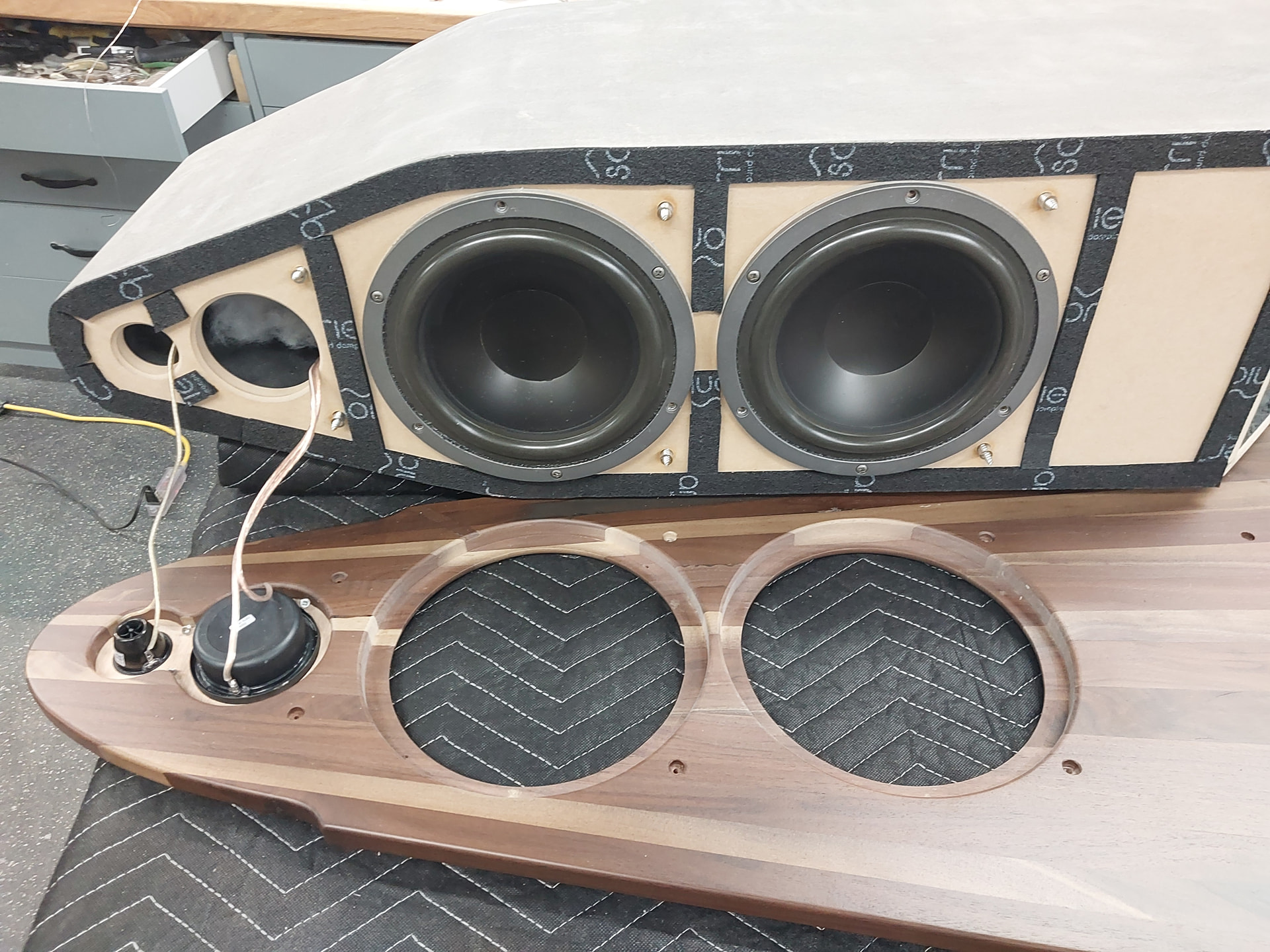
Progress today. Some things need to be changed. They have much higher sensitivity but they sound shouty compared to my Morel two way. The rear mounted nature of the design caused some reinforcement in places that seem impossible to remedy. I intend to make a low profile measurement stand for large speakers that I can stuff away under a futon, and retake some better polars. I measured the woofers together
and I think it would be better to measure them separately and then load into VCAD, especially if I want to try it as a 3 1/2 way
I was kindof worried about that when you mentioned rear mounting… BUT you seemed to have rebated them pretty far up into the material that left pretty minimal resess IMO. I find 3-was to be just dang ornery to work with. That is why I have quite the love-hate relationship with them. They have such high potential, but alot of potential to misbehave too. Takes alot of effort to reign them in compared to a 2-way, which is usually alot more straight forward.
I am finding that out those same things
Just gotta show them you are more stubborn than they are. Eventually you will hear something that tells you that you are on the right track. Sometimes it takes blowing a massive hole in your understanding and relearning everything you thought you knew about the subject. That happened to me several times.
1 Like
I was thinking that would be the case because Sound waves are spherical.
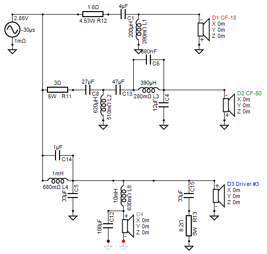
3 1/2 way is definitely the best way to go on these. Two extra parts, a 10 mH iron core and a 100 uF elecrolytic. Or I could use these poly caps?
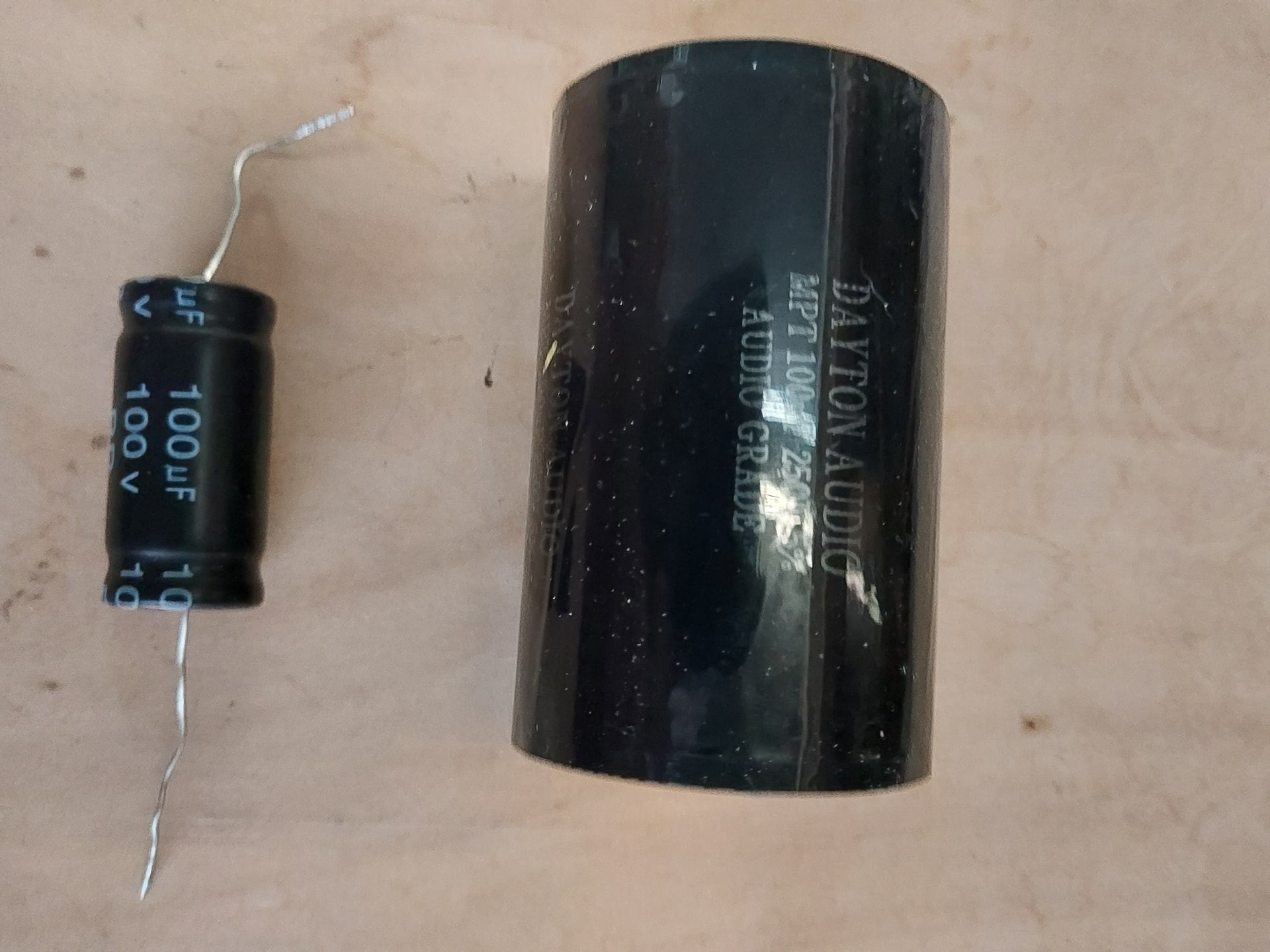
Lieutenant Dan , your Dayton audio cap has no legs !
7 Likes
Seems like poly is always preferred over electrolytic for passive XO. But I still sometimes use em on woofers due to cost and the smaller size is easier to physically fit into the circuit.
2 Likes
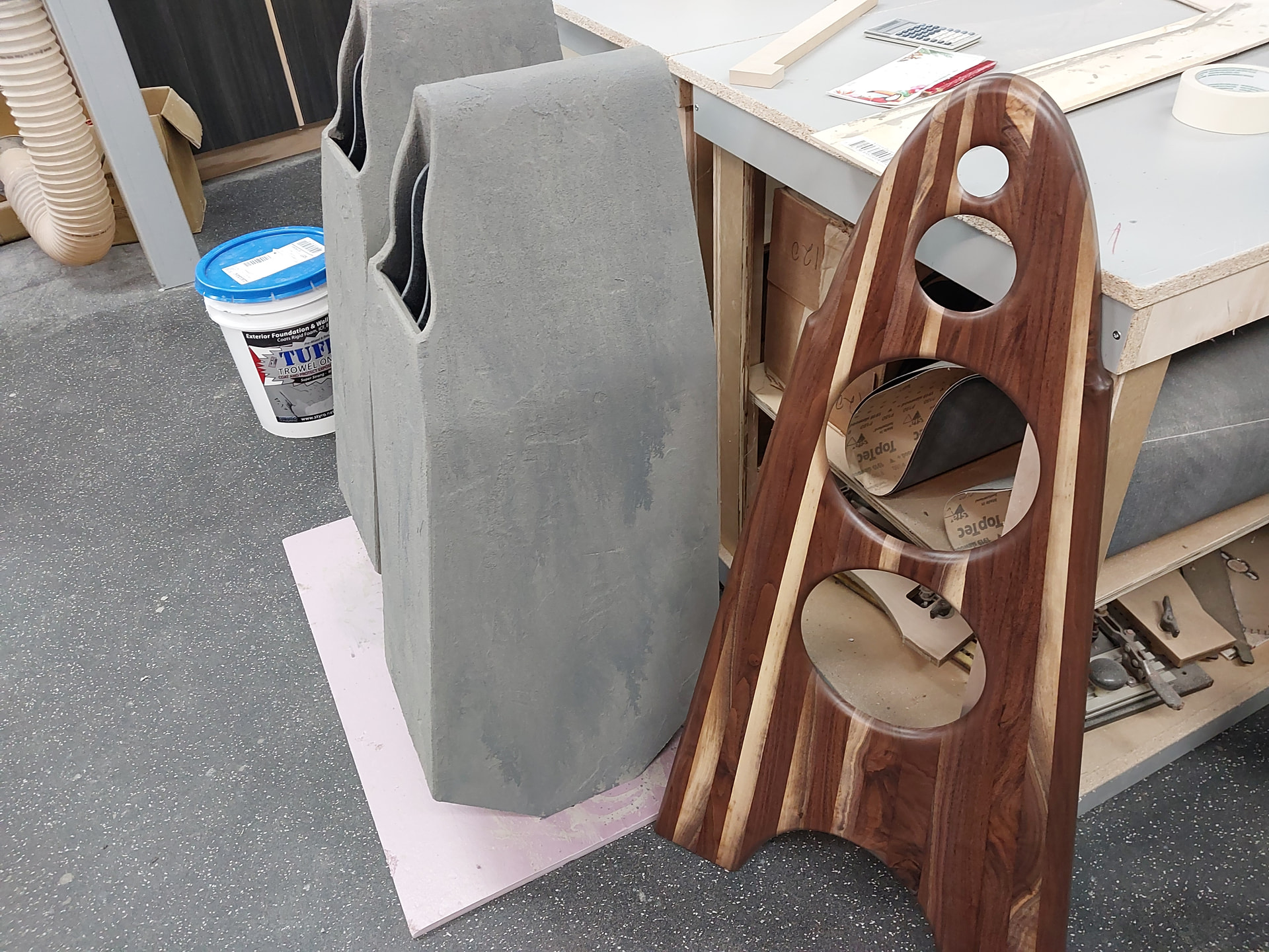
Second and final coat of stucco foundation coating. Some of the sprayed on grey will be either covered by a darker grey or sanded away. I am going for a distressed masonry look. The baffles are close to done. I think low sheen on the baffles 15-20 % gloss
5 Likes
I have applied a total of four coats on now because I’m weird. The cabinet is heavier now and much more inert. I like it. I’m thinking about changing my user name to stuccoman.
7 Likes
It’s looking good Rocketman!
2 Likes
Honestly, I would just attenuate 4k+ a little more.
2 Likes
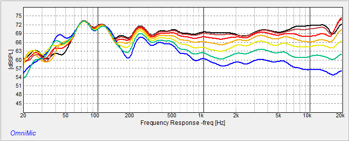
Serious question…why are you looking at line plots in Omni-mic when you appear to be using VituixCAD for the crossover?
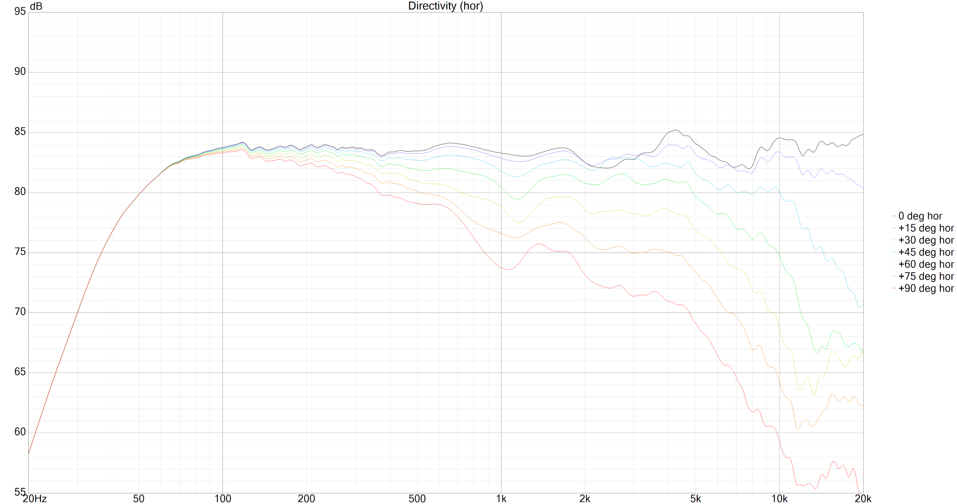
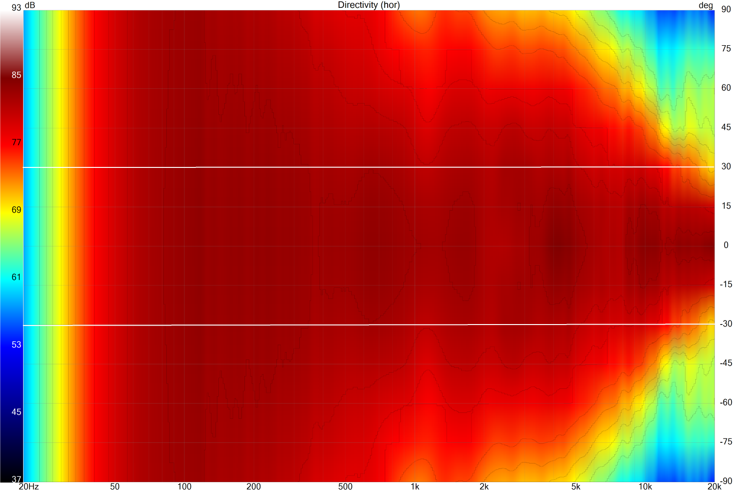
The reason I ask…I have a hard time drawing very concrete conclusions from the LINE graphs, other than I can see obvious areas of concern. I can see any obvious errors in the on-axis curve, but clearly, if I am looking at off-axis angles 0-90, I care about the directivity in general, sound power, etc. I find the POLAR graphs much more useful. In the example below (just one of my speakers I quickly loaded into VCad) I have the line graph and I know I have some elevation at 4kHz. But in the polar graph, I have set my contour lines at 2dB (I could have set at 1dB or 3dB if I thought it was more helpful). (The white horizontal lines are just edited in with MS Paint.) I can see that if I care about 2dB deviations within a fairly narrow window of +/-30 degrees, I probably want to bring down not only the area at 4kHz but also 1.5kHz and 10kHz. However, I can change my contour lines to 3dB and look at +/-15 degrees, as in the third graph, and maybe I don’t actually care to change anything. (Sorry, the contour lines are pretty hard to see and I can’t make them thicker.) Of course, at some point, it comes down to actual listening with your ears, but in my case I probably trust measurements a little more than my ears.

I am not getting perfect agreement between Vcad and Omnimic. I am doing something wrong. I wonder if I need to load separate zma files for the woofers even though they are the same. So today I connected the woofers in parallel with the big L and C included on the lower woofer and made new files and entered it as one woofer. Notice that I have the grounds opened on the lower woofer.
I noticed that two woofer in parallel sum 6 Db throughout there entire range, but this is not possible
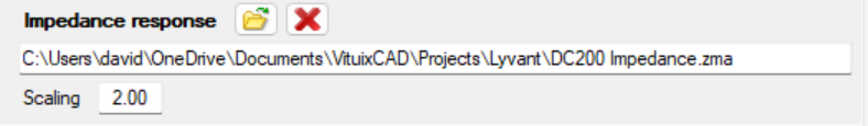
Depends on how you measured them and how you have them entered into VCad. If I remember correctly…If you measured impedance in the box with both woofers wired in parallel, but have two woofers modelled in VCad when doing your crossover, you need to scale the impedance by 2.0. Screenshot from the bottom of the DRIVERS tab.
If you just want to see the visualizations (line graphs, polar, etc.) just load the frd files your graphed in Omnimic as the response to driver one in the DRIVERS section, and connect the amp to the driver in the CROSSOVER section.