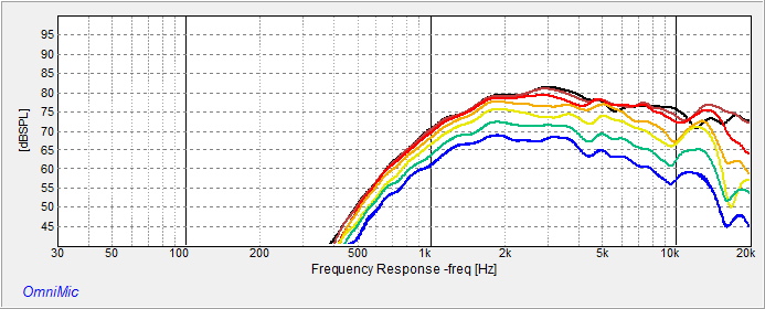
IT looks pretty good to me but it really depends on what you are trying to accomplish using them.
Do you want wide or controlled dispersion?
A better directivity match to a seven inch woofer, at XO, 1 to 1.2KHz? and maybe even second order slopes and I was also thinking maybe a design axis midway between woof and tweet due to better time arrival. And better looks, to me that is. I am not a fan of exposed screws
OK, you now have a spec but knowing the directivity of the 7" woofer on your baffle is the next set of sweeps needed to determine where the match needs to occur, I think.
Yes?
First time you, first time me! First time for everything.
Someone once asked me. What all can you do? And I answered I don’t know. I haven’t tried everything yet.
This is a killer project if what you are attempting is that weird Transmission-Line in the .PDF file you posted!
Keep going, dude.
Take individual 0-90 (or 0-180) measurements of each driver/baffle combo and then load all the data into VituixCAD. Then connect the amp to each driver individually and look at the directivity, power resp, PIR curves, etc., of each driver/baffle combo. This will show you how good or bad the native directivity of one driver/baffle combo is with respect to the native directivity of another driver/baffle combo.
In your graph above, there is some bunching at 5kHz. But with an xover near 1kHz, this may not be an xover related problem. The 5kHz bunching may be something created by the shape of your wave guide. Looks like you are rolling off too fast for a 1kHz xover. Looks like 2kHz would be better.
Was this the raw driver on the baffle with no rolln off of the signal or inline cap?
Another thing to consider is what is the distortion doing. Even though the waveguide can help roll off at lower frequency you may still have distortion that you need to avoid.
Same is true for the woofer. Cone breakup can be a real pain in the butt. I have seen some drivers look good higher up untill you take a few off axis measurements.
That was the area I was concerned about, 5 to 6K. I think I know what I am attempting and why but what to prioritize.
Yes, all things must be considered.
And prioritized to a point in which the priority can be compromised.
Would this be the Dayton EC-30-4? I have a pair of these as well and was thinking of making an insert for my large IEC test baffle and running up a set of polars after the SDC is over. The 0-60 curves on the datasheet look very good. Try adding temporary cardboard “wings” to your baffle board and measure again to see how if affects the bunching.
I have not yet bought the EC-30 tweets. I was just trying to get some things figured out so I was using some Morels which I intend to use in another project on the back burner.
This is my waveguide rig. Version 1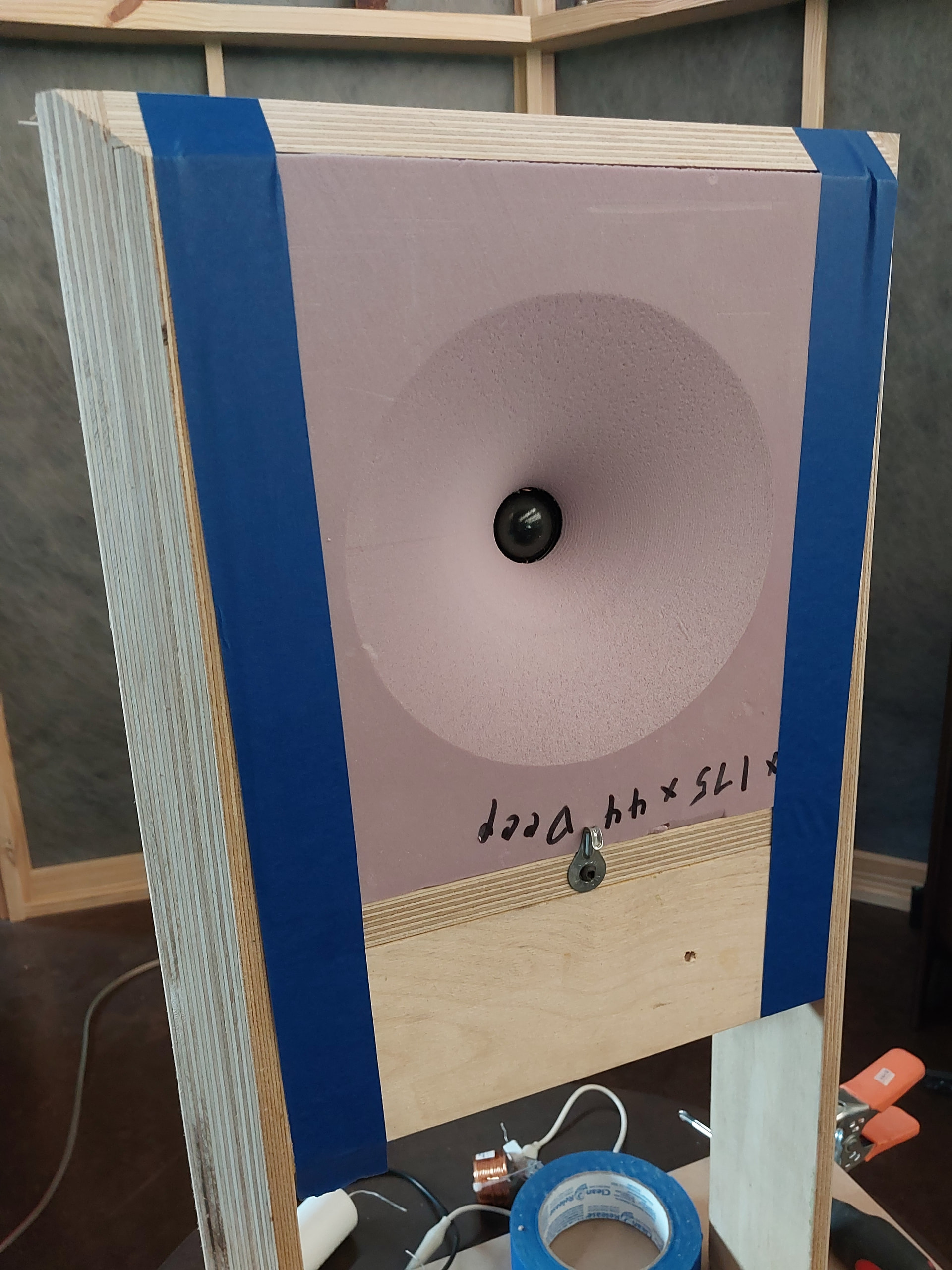
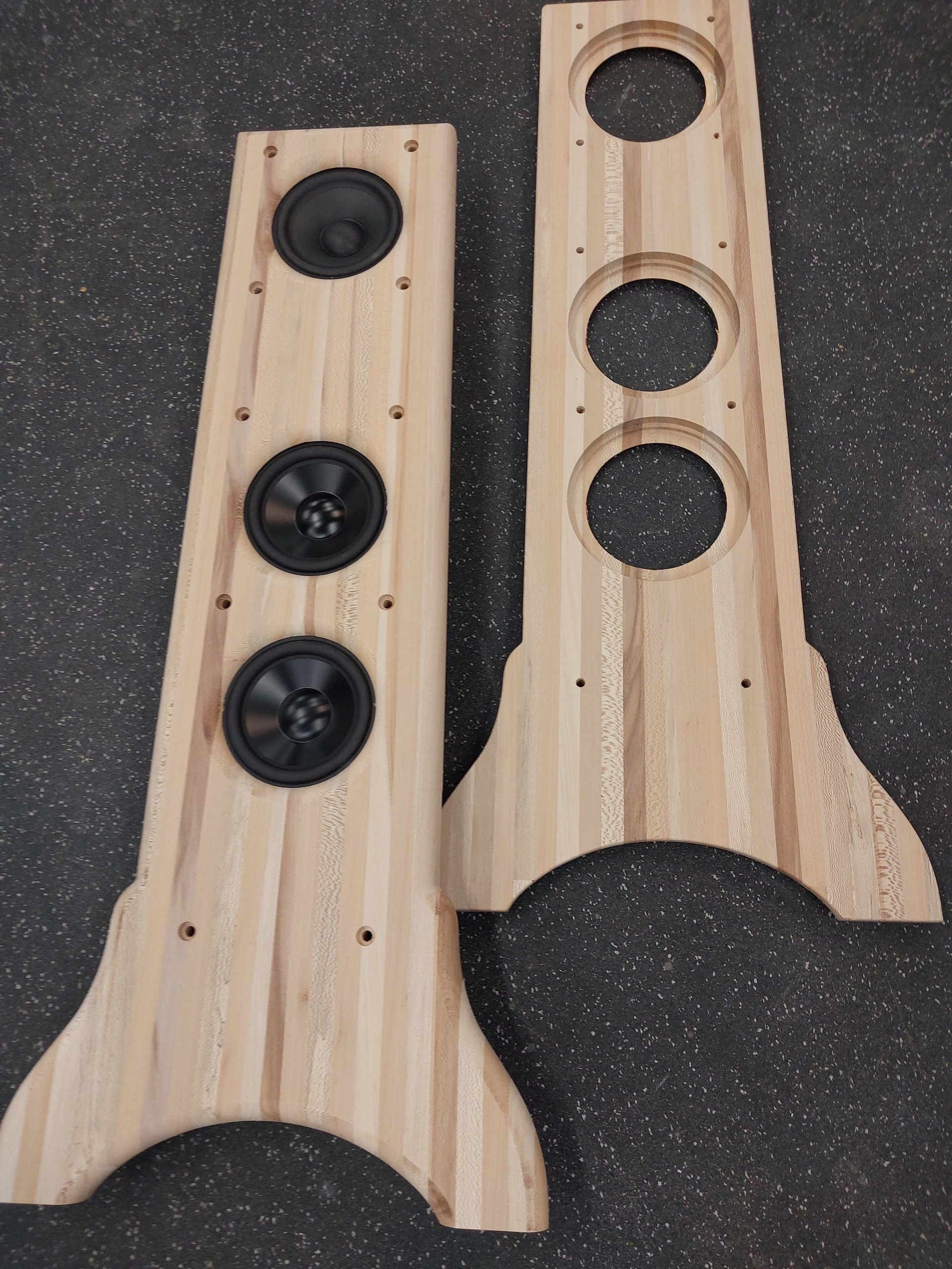
Baffle progress today on speaker Sunday. I don’t have tweets or the experience with waveguides, so that will happen later. I drilled some shallow 3/8 inch holes into my spoil board to be able to remove the baffles and reinstall them in the exact location, but I need to figure it out soon, so some of you could probably help me. I don’t even know what to look for. I assume a dip caused by throat to diaphragm mismatch. It is my first time so I don’t expect everything to be great. Waveguide should should simulate mid. cone profile, correct?
.I am starting with Dayton EC-30 tweet with a waveguide 35x150x32 mm deep
They did have a bit of a bowling alley look so I ripped them straight down the middle and tapered the two halves on the jointer so now the grain doesn’t run out on the edges.
I had a duplicate and I cant delete it so I am typing words to satisfy the powers that be.
Are you starting with the one Augerpro posted in diyAudio or one of your own?
Waveguides are weird and mostly depend on the tweeters dome and surround profiles. The diameter and depth of the WG will be influenced by the size of the midrange though want to pair it with, but the rest will depend on the throat profile.
From rudimentory research I got the feeling that alot of domes don’t work the greatest with a steep throat area. Such as a more traditional horn shape. Or, if they do have a steeper throat, I see alot of times the surround will be partially covered by a smaller throat opening.
Thanks I need to investigate augerpro. I suppose I could try one of his STL files, I dont even know what stl means. I watch my wife using simple tools like sandpaper or a knife and it is not great. She is very smart, but there is a disconnect between her mind and her hands. An impedance mismatch maybe. I do not suffer of such things, my hands and mind are of equal intelligence.