Care to post the final schems, or are you not there yet?
Every time thread is bold for updates, Slipknot goes through my head.
Quite an assortment of parts to have two 3 ways fully stereo going - but I’m sure there some here with an even larger pile. Someday someone take a pic of all the gear, parts and drivers for ‘diy speaker designer starter kit’ - though i know there that old thread about driver stash.
Yeah, just as soon as I get around to updating the schematics, LOL. I need to do that and get final measurements. I think they’re pretty much done.
I noticed you mentioned much more bass on the peerless woofers. From your measurement graphs above, the F3s look like 75hz (MCM) and 58hz (Peerless). From simulation, they should be much closer. Grey trace is the MCM behind the Peerless sim. Any ideas?
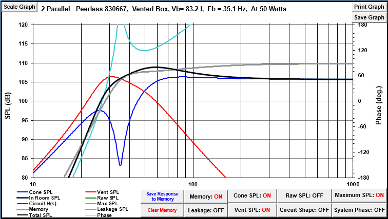
Those are gated measurements, gated at 3.5ms so everything below 285hz is just made up when imported into Vcad. I don’t blend the low frequency response in when modeling because I can never get the phase right on the blended measurements. I’ll pop in a blended response just to see where I’m at for level matching along the way.
2 Likes
If you were to match the SPL at around 200-300hz that would realy show the reduction of bass energy.
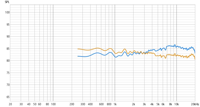
I’m not a very smart man, so hopefully someone can explain this to me like I’m 5. After spending 45 minutes trouble shooting something that should have taken 5 minutes, please help me understand why when I connect my speaker wires (positive and negative) from the amplifier to the tweeter circuit, I get the blue curve and when I connect the speaker wires from the amplifier to the woofer circuit I get the yellow curve? All inputs and negative legs of the filters are tied linked together via alligator clip leads.
I bought some alligator clip jumper wires a few years ago and they suck, not even soldered.
2 Likes
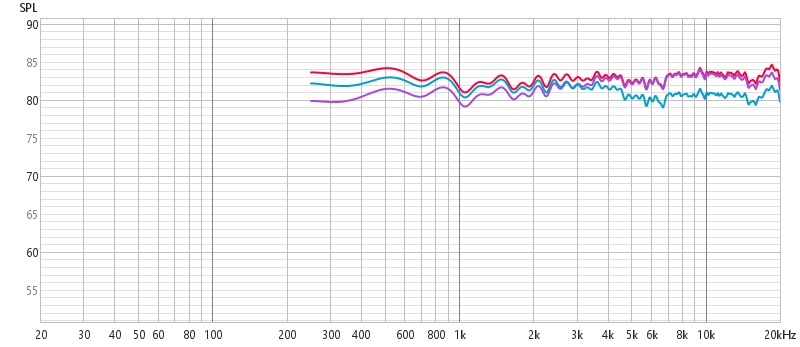
So today I discovered my entire life is a lie. Red line is running a lead directly from the speaker wire coming from the amp to each filter network (positive and negative). Green line is connecting the speaker wire to the woofer filter, then daisy chaining the positive and negative to the MR & Tw filters (how I’ve been voicing). Purple line is running speaker wire inputs to the Tw filter network, then daisy chaining the positive and negative to the Tw & woofer networks.
I don’t understand what is happening. When I’m simulating in Vcad, the order of how the positives and negatives are connected has no bearing on the results. I ran an impedance sweep (not posted, didn’t save them), and they are very different as well.
I’ve voiced everything with the networks daisy chained from the woofer circuit with that as the input. When I was going to install them, I was going to run an individual lead to each filter network. That won’t work, they’ll have two completely different response curves. I have the crossovers soldered.
Because I’m OCD I like the idea of having each filter with a direct input for serviceablility. But since I have them finished and voiced I guess I’ll just have to finish them with filters being daisy chained from the woofer filter?
I still would like to understand why this is happening. According to a Vcad and my rudimentary understanding, it shouldn’t be?
A connection that is less than ideal. Cold solder joint, corroded joint, loose or a combination of these is not purely resistive. They do weird shit.
1 Like
See if that same issue happens with the other speaker.
>> meaning L vs R
1 Like
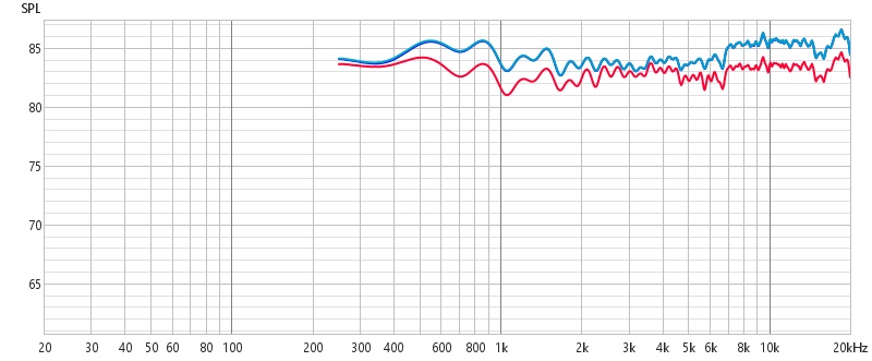
You had ‘er right the first time. It was resistance from the alligator clip leads. The blue line is with 14ga speaker wire supplementing to the alligator clip leads. There’s actually two lines there, but they overlay each other completely. One is going to the woofer circuit first, the other is straight to each network. No difference in response. The red line is the alligator clip leads going to each network for comparison. I knew the leads would have some resistance but I was expecting tenths of a db, not 4-5db worth of resistance.
This sucks. I had all 4 networks completely soldered. Now I have to start the voicing process completely over.
So how are y’all connecting everything if not with alligator leads? Or did you make your own with thicker gauge wire?
I use the wago style for the components, but when connecting the input/speaker wires how are you doing it?
Sorry I am a new guy and I would like to step aside
The alligators I have I made myself by screw terminals or solder.
Wagos are great!
There are specific wago style blue+red screw down connectors you can mount to a board and make circuit nodes if you feel so inclined. @A4Eaudio could likely help you find the parts.
Eric has a board with simple speaker spring terminals.
Way back, Peter Smith (Pjay) used steel springs glued in holes. Alligator cilps or any kind of spring terminal suffices.
1 Like
Sorry to disagree, but your entire life is not yet fulfilled.
1 Like
I think I’m going to make my own leads with alligator clips and 16ga wire. In my head that seems the most flexible
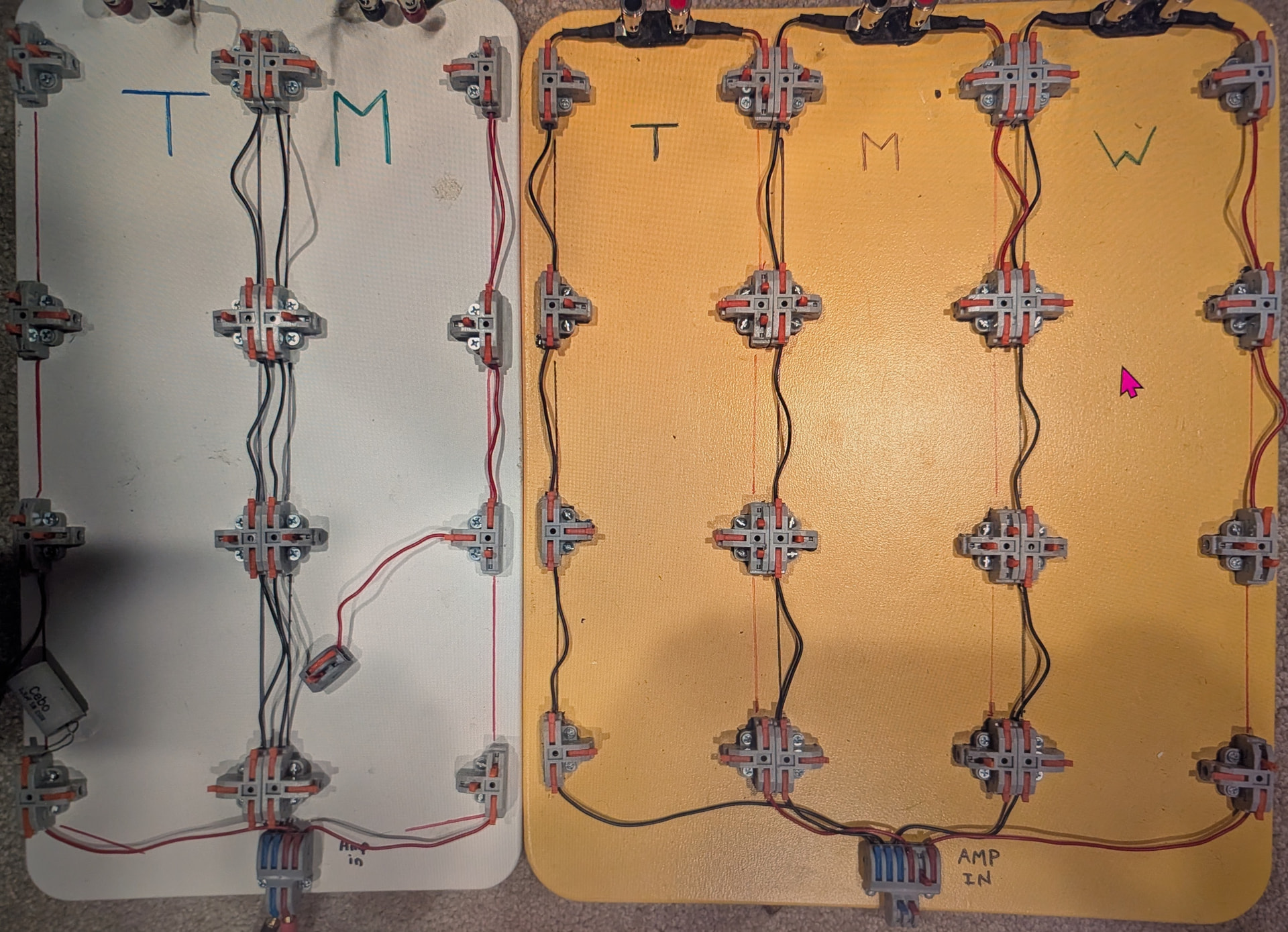
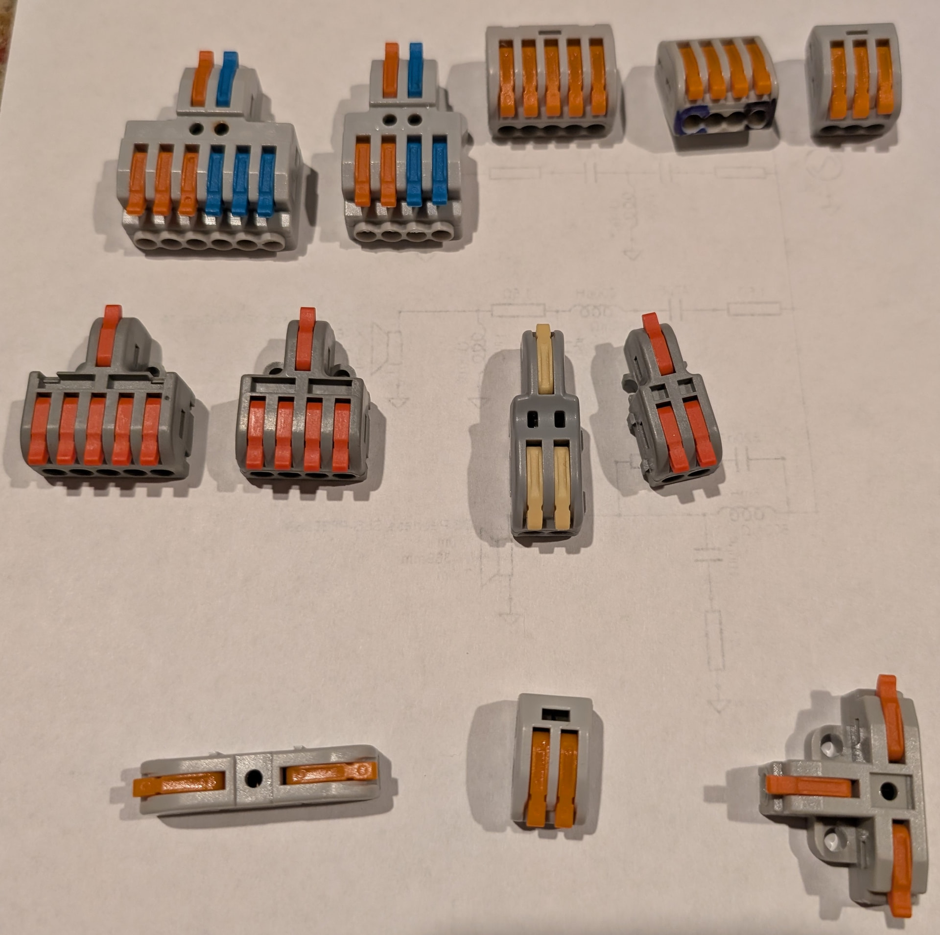
I have built prototype boards for 2 ways and 3 ways using “T” shaped Lever Lock connectors. The prototype board has to look like a schematic from VituixCAD or I’m too dense to put the parts together correctly ![]() . However, I am about to build new, revision 2, board using 3 and 5 conductor connectors. They come in tons of variations (see below) and I have several crossovers inside of speakers completely connected with Lever Lock connectors because I wasn’t convinced that I had a good FINAL xo that I wanted to solder up. I have bought mostly GKEEMARS branded ones off Amazon lately, but they all seem to be mostly the same. The T-shaped ones and a few others take small screws, but I mainly epoxy them down for the prototype boards. [The 2-in/6-out and 2-in/4-out are particularly good for taking the signal from the amp and sending it off to the individual drivers. You can see them at the “amp in” location of the prototype boards.]
. However, I am about to build new, revision 2, board using 3 and 5 conductor connectors. They come in tons of variations (see below) and I have several crossovers inside of speakers completely connected with Lever Lock connectors because I wasn’t convinced that I had a good FINAL xo that I wanted to solder up. I have bought mostly GKEEMARS branded ones off Amazon lately, but they all seem to be mostly the same. The T-shaped ones and a few others take small screws, but I mainly epoxy them down for the prototype boards. [The 2-in/6-out and 2-in/4-out are particularly good for taking the signal from the amp and sending it off to the individual drivers. You can see them at the “amp in” location of the prototype boards.]
I also have some nice copper alligator clips that have very good clamping strength and you supply your own wire, so 14 or 16 AWG or whatever your preference is. DROK 20 pcs alligator clips.
3 Likes
How have the copper alligator clips held up? Pure copper has a tendency to tarnish or corrode over time. Be nice if someone offered a gold plated version.
Years ago I measured the cheap alligator leads PE sells and threw them in the garbage. I made my own with robust gator clips and 16awg wire, no more than 6” long.
1 Like