I’m kind of sad. I asked my wife to help me do the zip thing. I then asked if she would help with the unzip thing and she declined.
2 Likes
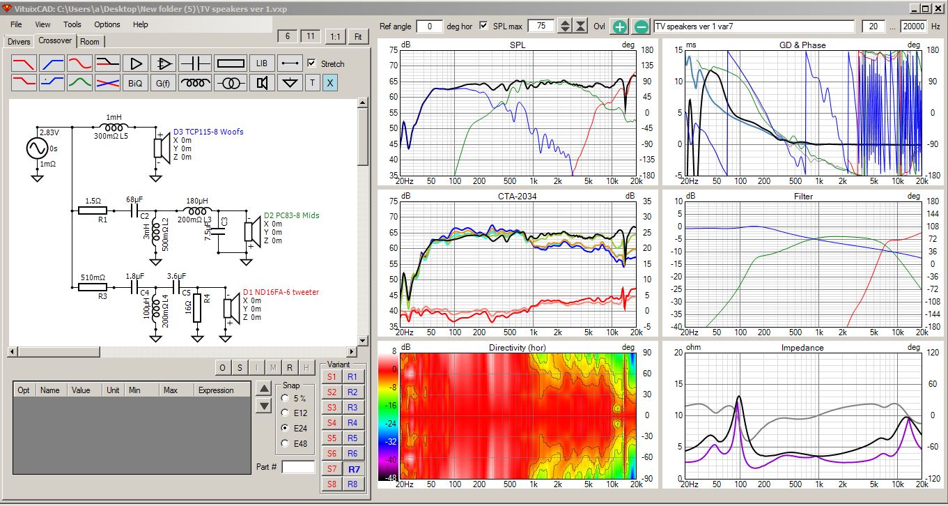
Clay, I’ll start out with screenshots of my diffraction and merger pages for the TV speakers. Please treat this as a VCAD training exercise. Feel free to step in and point out any errors or typos that you see in my work. Or how you would do things differently, because there are often several different ways of doing the same thing.
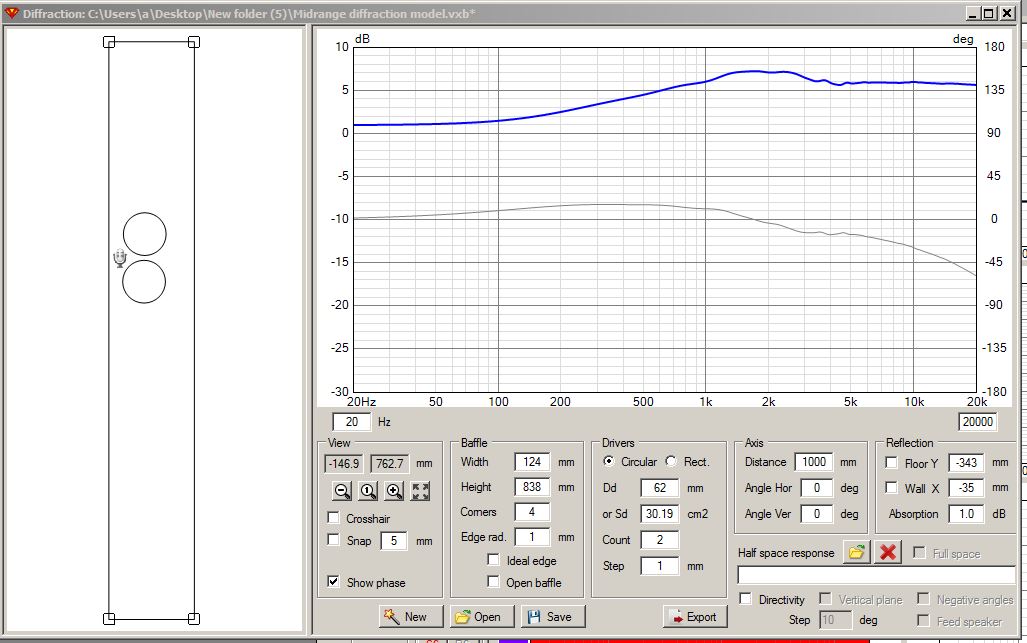
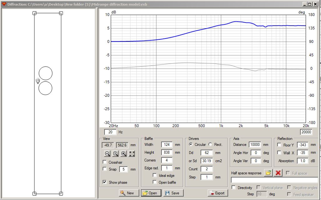
Midrange diffraction models. One for 1000m and one for 10000mm:
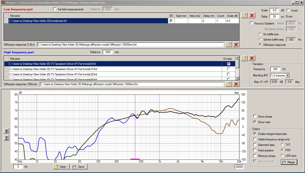
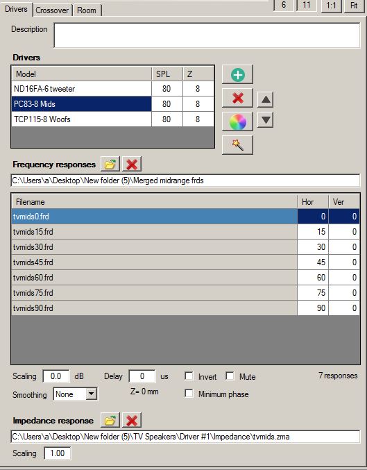
Midrange merger screen:
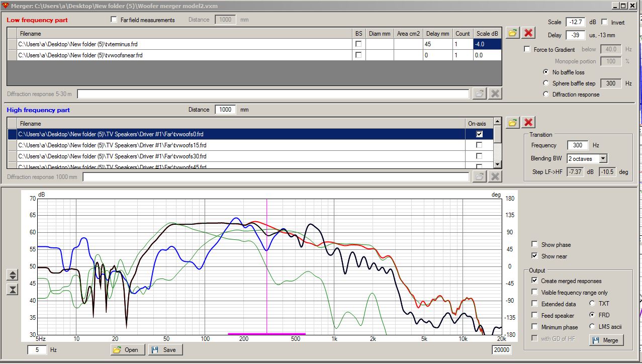
Woofer diffraction screen:
NONE. I decided to skip the woofer diffraction model and FRD creation because the two woofers are only 7" above the floor. The floor boundary reinforcement effect will fill in for the baffle stepping loss, so no adjustment is necessary here.
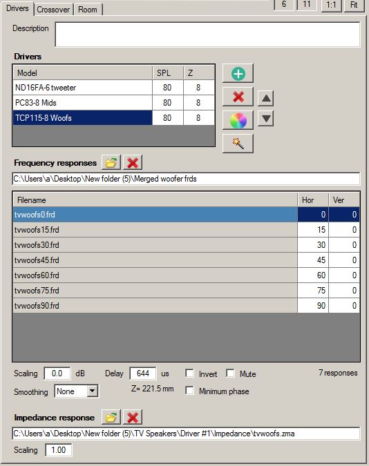
Woofer merger screen. This was a difficult one due to the wonky looking response curves. I guesstimated the merge by striking an average through the squiggly congestion:
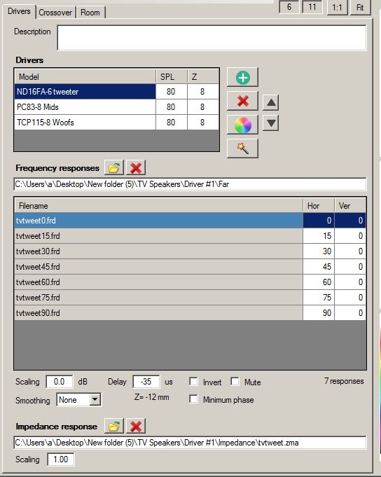
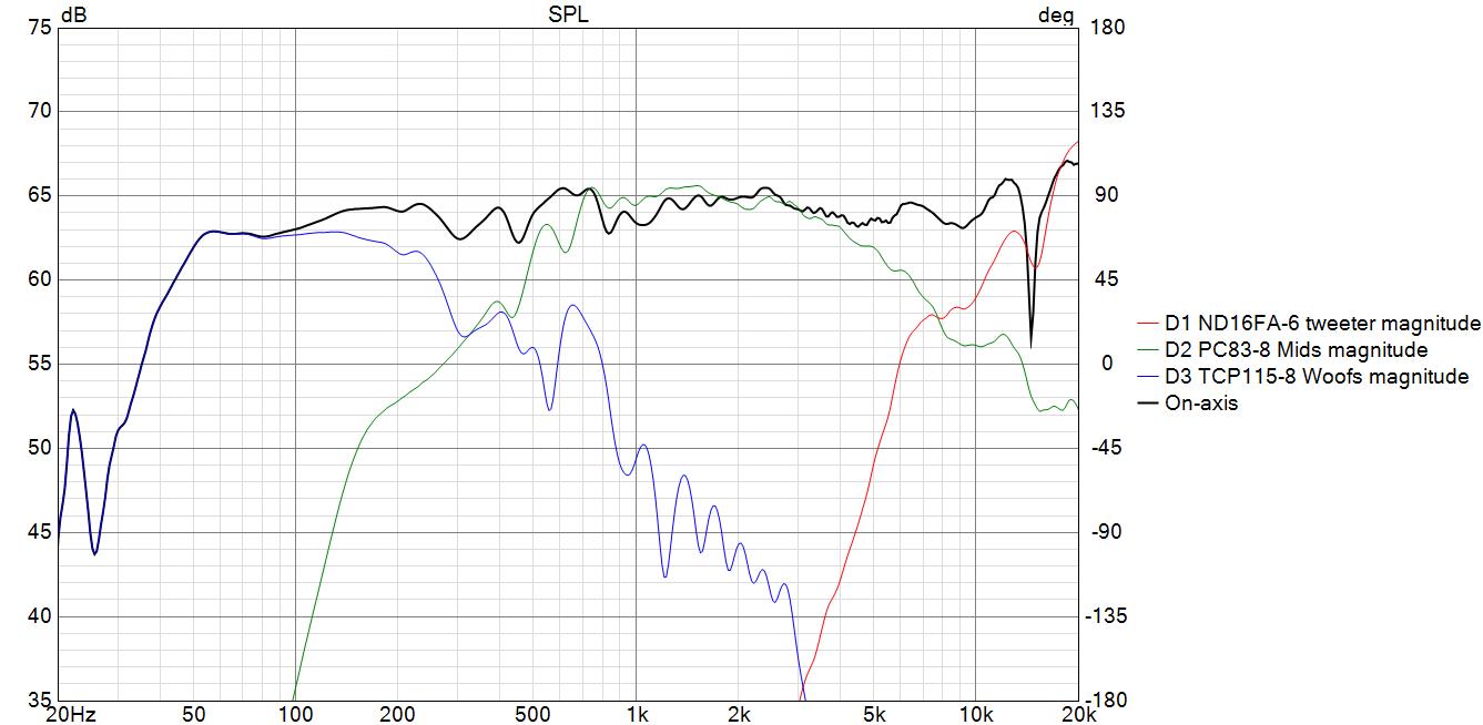
Here are the driver screen tabs, showing the offsets. The midrange is the anchor with no offset. The tweeter shows an offset (delay) of -35us or -12mm. The woofers show an offset (delay) of +644us or +222mm. Note: These offsets are only accurate for the on-axis set of curves, not the off-axis set of curves. This will therefore introduce a certain amount of error in the model.
Dang Bill. I appreciate your efforts. I realize that my FRDs were less than ideal. I think I have enough parts to build your first attempt XO on speaker Sunday. And share the results. My sims have not been agreeing with measured lately on my 3 ways, so I know that I need to do things differently. I could pretend to know about all of these things that I have never done before and why they are important, but that would probably go over as well as a fart in church.
1 Like
I built Bill’s crossover last night and the results were impressive. I couldn’t figure out why the diffraction model was necessary so I asked Grok or whatever its called. My Omnimic picks up the diffraction effects, but VCad needs to know how much is caused by the baffle shape and driver location . The diffraction model is needed to accurately simulate a desired result. I guess its time for me to learn how to do it.
2 Likes
I plan to increase the slope on the side woofers and also the mids low pass because of the cancellations in the 5-6K region, also I have an obsession with symmetrical slopes.
2 Likes
Great! ![]() So now you can try a validation measurement with OmniMic to see if you can get a reasonably close match to the model. Ignore everything below 500Hz, as this will not match, not even close. Nor will any of the off axis curves match in a validation measurement using OmniMic(20k). Only the on-axis FR above 500Hz should provide a reasonably close match. You need to put the speaker and mic in the exact position that you used to make the initial set of on-axis modelling measurements. So if you do not get a good match, move the mic around a little bit until things start to line up. Remember, it is almost impossible to place the mic or speaker in the exact position between sessions, so you need to experiment a little.
So now you can try a validation measurement with OmniMic to see if you can get a reasonably close match to the model. Ignore everything below 500Hz, as this will not match, not even close. Nor will any of the off axis curves match in a validation measurement using OmniMic(20k). Only the on-axis FR above 500Hz should provide a reasonably close match. You need to put the speaker and mic in the exact position that you used to make the initial set of on-axis modelling measurements. So if you do not get a good match, move the mic around a little bit until things start to line up. Remember, it is almost impossible to place the mic or speaker in the exact position between sessions, so you need to experiment a little.
Since we used the driver delay fields on the driver tabs to enter the offsets, not the X/Y/Z CAD screen values, the measurement should be valid at a 1 meter distance. VCAD only triangulates the measurements out to the 2.5 meter listening distance when you enter X/Y/Z data on the CAD screen AND you enter 2.5 meters as the listening distance in options.
If all the X/Y/Z values are zero, then the VCAD model is valid at whatever measuring distance you used to make the model.
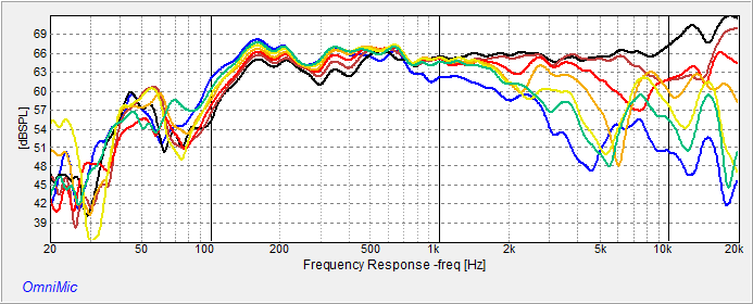
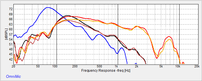
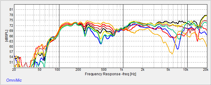
Every time I have tried a TL with dual woofers I have had problems. My not a rocket speakers had issues, my tripod speakers and now my TV speakers are kicking my ass. Side firing woofers add further complications. I tell myself that TV sound is not that important but I need to learn this stuff and I have never regretted trying to do better. The problem is a 3Db. boost at twice the tuning freq. Sounds terrible, especially if I attenuate my mid and tweet to that level. On my not a rockets I went 3 and a half way with 14 mH total on the bottom woofer and I think it worked. Here are some near measurements on my TV Speakers.
TV Speakers.zip (246.1 KB)
Blue is terminus
Black is woofer near thru filter
Brown is woofer near thru filter but hand braking other connected woofer
Red is woofer no filter
Orange is woofer no filter while hand braking other connected woofer
where are you blending, regardless of where the woofers are position, your far / near would get blended around 400-500 hz and then you use that to do your XO, even if you are going to cross lower then 400 and the woofer is side firing. Side firing, best is to blend under 150, can go up about 200. The port seems fine, will lift up the bottom end. The woofers seem to take care of Bsc due to the gradual rise from 1khz (unfiltered, unbraked? - though you can’t really measure one driver - even if they are disconnected, it’ll act as an PR, so it’s a packaged deal). Where is the 3Db boost or was that the boost?
I am missing something, so want to better understand what you are seeing as the issue.
Bill’s Sim seems flat enough, there’s always goign to some ripples in the lower end
Yes and they sounded super thin. Nothing much that I could hear below that. I am going to experiment with overdamping the line and or converting it into a 3.5 way or powering with a 2.1 Amp. Doesn’t make sense to have more money in XO parts than the drivers are worth.
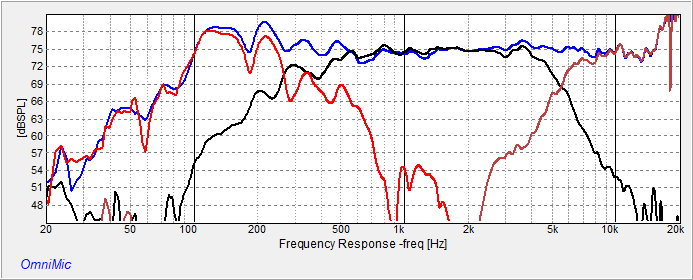
I haven’t even tried to blend yet, unless making a smoothie. My room is very much built for sound. Probably overdamped but I like it. The walls have 7 inches of fiberglass and 3 layers of fabric. The ceiling is sloped and also has even more fiberglass and no hard paneling. I think if I raised my measurement stand even higher I could get fairly reliable measurements down to 50. I’m gonna try it.
A typical anechoic chamber can measure down to 200 to 80Hz.
I am certain you are correct. And I was probably off by an octave, but I also used the word fairly which means kinda sorta. I have it sounding better now, however not enough better. That tiny tweeter is a complainer. It needs an L pad and then it can play down to 6 K 4th ord. happily. The pc83’s are very easy to listen to. A simple 2nd ord. electrical with a notch around 10K. Here is where I am at now with the project. Kinda sorta.
I almost used the word “reasonably” but that would have been even more of a stretch.
Thanks for helping me with the tags. I’m a late bloomer. But I’m not a non-bloomer.
1 Like
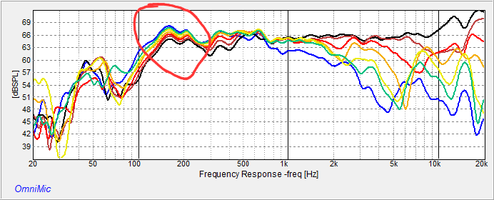
Here are some measurements on my not a rockets in my fav. spot in the sound room. Blue is with it sitting on the floor, black is on an 18 inch stand and red is my 33 inch measuring stand. 1/6 smoothing
3 Likes
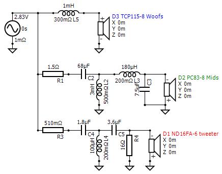
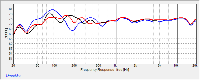
Here is the crossover that I am currently listening to. It’s back to a 3 way. I added a parallel tank on the woofers for -5 Db at 170 Hz
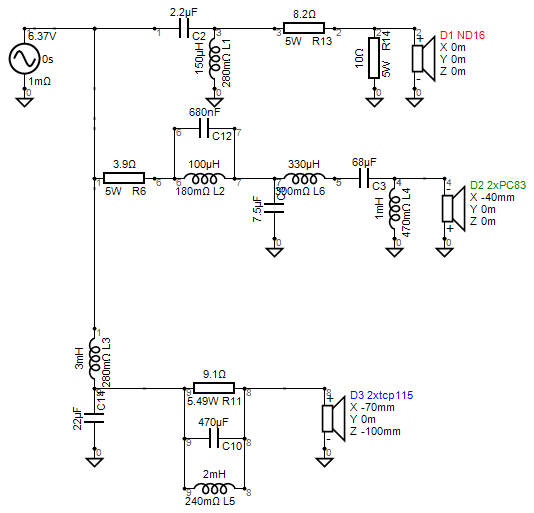
.The polars are a mess because of the off center tweeter and side firing woofers.
Shouldn’t the X,Y,Z values for all drivers be zero?