As long as you have the nearfield spliced in right, Xsim can model the cap addition, or use the midrange section on the PCD or WinPCD.
Ah, yeah having LF measurements would be required for accuracy. I suppose I mostly was hoping to get an idea what the shape and magnitude of the boost is. But swapping in caps and listening should give me most of what I need to know.
I imagine near 1/2" of total excursion on a couple 12"s should suffice for normal critical listening.
1 Like
Well shoot. The recess cutout is a little too small diameter for the woofer. The OD on the PE page says 13", but the data sheet specifies 332mm. Which calculates to just over 13 1/16". I set the circle jig to 13 1/16" and used the bit centering tool, but there is some slop in the setup and it ended up a little smaller than that. I’ll need to sit for a while with a piece of sand paper wrapped around some 3 or 4" pipe and manually sand it.
The ring on the frame was meant for surface mounting. It is pretty deep and flares out ever so slightly. So it is hard to get an accurate mesurement. I can get it to fit in a bit if I flip it over, so fortunately I’m not way off.
My brother-in-law got me a Dremel tool kit years ago - I’ve (needed to) used it more often than I’d like to admit for this and other boo-boos.
Sometimes a rabbet router bit can shave that by riding the through hole with its bearing.
2 Likes
Neat solution in the appropriate use case! (sounds like my kinda fix) Probably wouldn’t work here though.
OD vs ID is quite large on these. I did 3/4" difference all around as that would engage plenty of gasket. But the overall max OD vs min ID calculates to 24mm of flange. Pretty huge.
I tried just working the opening with the lowest grit paper I had within reach (150grit) wrapped around a short section of 4" pipe. After about 1.5hrs I was close enough to get the woofer literally stuck in the opening most of the way in  .
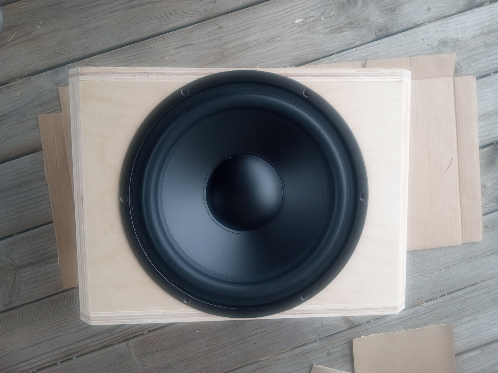
I finally got it back out after some prying in the screw holes and smacking the enclosure while woofer was faced down to shock it into breaking loose. But it still tried to rip off some of the veneer around the edge on it’s way out  . Yeah not a big fan of this plywood.
So I still need to work more on this opening… then on to the other one too  . I have had poor results using powertools freehand to enlarge openings (ends up pretty hack looking).. But I’m thinking if I can use a dremel bit to gouge out the inner corner. That would shrink the total vertical surface needed to sand, and make for quicker hand sanding while all the dremel carnage remains invisible below the surface.
I would make a template and fasten it to the baffle with double sided woodworker tape and cut the rebate with a top bearing bit. That way you can test fit the template before you cut the baffle. It would also let you resize the rebate you’re trying to enlarge.
3 Likes
This is how I do all mine. Templates are so much easier in my opinion.
1 Like
I ended up taking a dremel ball carving bit and removing material around the perimeter below the surface. This greatly reduced the surface area to sand down and made much more quick work of it. I may have gone slightly overboard with the sanding, but I don’t think it’ll look too bad. By this point I’ll probably be embracing the imperfections and lean into an old prototype aesthetic.
1 Like
If I do try out the capacitive boost. Would that pose any issue to a tube amp?
Honestly, I’m not sure.
Too late to be of any help, but an oscillating drum sander would have been my suggestion for the fit issue you already overcame. Assuming one was available, of course.
I have found that if you go to fast or your bit is dull, it will do that as well. But some stock is just trash and it will happen anyway.
As far as the tube amp question, it really depends on the impedance curve. Usually Cap boosted designs drop the impedance very low but with tube amps I would worry about phase more. But tubes don’t like low impedance either, usually.
But and usually are my 2 favorite words… apparently 
1 Like
A cap assist raises the impedance below Fc in most cases. It doesn’t lower impedance to my knowledge.
If you use a shunt coil as well to boost power input by lowering impedance, however, then that is likely not going to make tube amps happy.
Tube amps are for guitar players
4 Likes
Yeah well, spinning vinyl through the tube amp into my horn speakers might not be everyone’s cup-o-tea. 
Hmm, if I build my own turntable that would be a 100% DIY setup… Oah no.. Why did that have to pop into my head 
1 Like
There is no bottom to the rabbit hole.
I love the idea of a tube amp, in practice it is hard to justify.
2 Likes
Keep your table, but you could give a DIY tonearm a go !
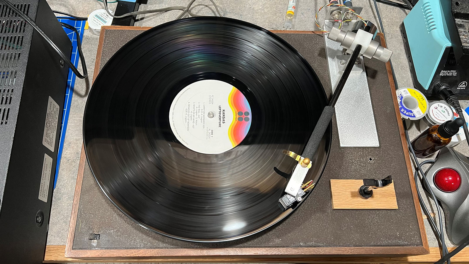
I second the DIY tonearm idea! It’s a fun project. I built a funky unipivot arm out of surplus bits and an arrow shaft. It seems to work OK and probably doesn’t hurt the LPs, but it is kind of finicky.
6 Likes
I have been listening to my 4 wpc SET 6V6 tube amp now every day on my work desk for about 5 years. I’ve switched in and out other small amps (solid state AB and ClassD). I always go back to my DIY 6V6 SET amp. Never have had to replace any tube so far.